
Elite Forces 1/18 F6F Hellcat Part 14 - Miscellaneous Stuff
By Rodney Williams
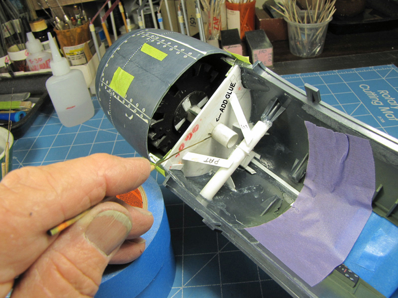
My first two photos show you how I achieved almost perfect alignment when I attached the engine.
To start with I dry fit the finished engine into the firewall then dry fit on the cowling. The cowling was adjuster for fuselage alignment. I used some of my strong holding green tape called "SCOTCH~233+" and taped the cowling to the fuselage.
The engine fit rather tight in its´ home made firewall bracket, however I was able to move it in all directions as explained in a previous story. When I "think" I had it perfect, I added one "micro-dot" of "super thin" super glue to the 1/2" round shaft that stuck past the firewall, (first photo).
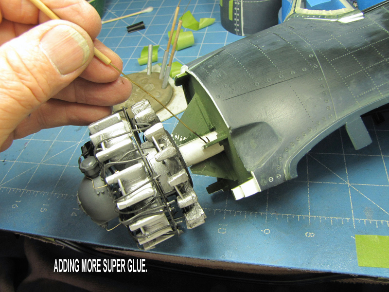
I carefully turned the model in several directions checking for engine and cowling alignment. I removed my green tape and took off the cowling. My second photo shows you where I added lots of super glue to the front section of the firewall. I re-attached the cowling and again checked everything for alignment. It met my approval.
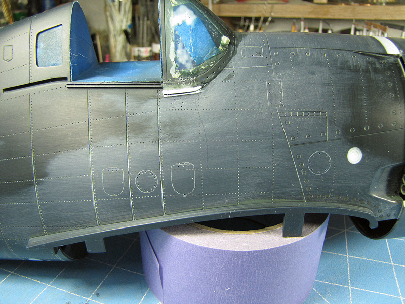
It was time to glue in the two small side windows with some Future Floor Wax (FFW). I have used this stuff for a couple of decades and when it is dry, it´s hard to take parts apart. I just turned the fuselage upside down and dry fit in both windows from the bottom and adjusted them by reaching into the area from the top of the cockpit´s opening. After the FFW dried a couple of days, I carefully added a couple of "micro-dots" of super thin super glue.
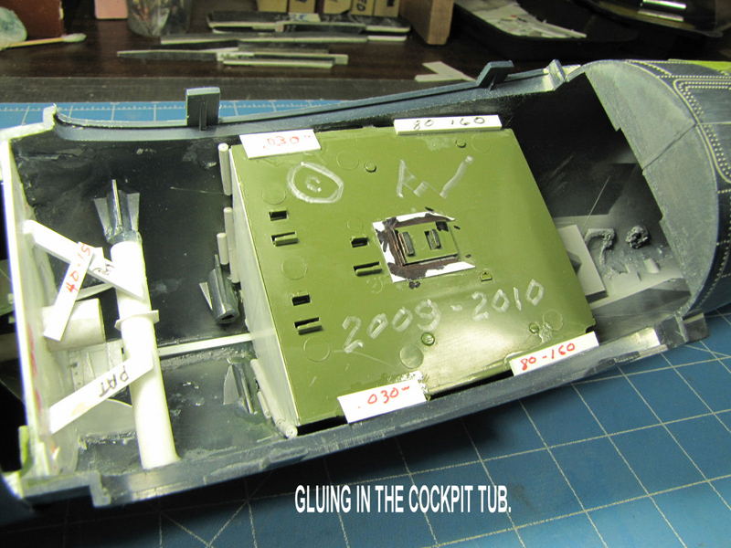
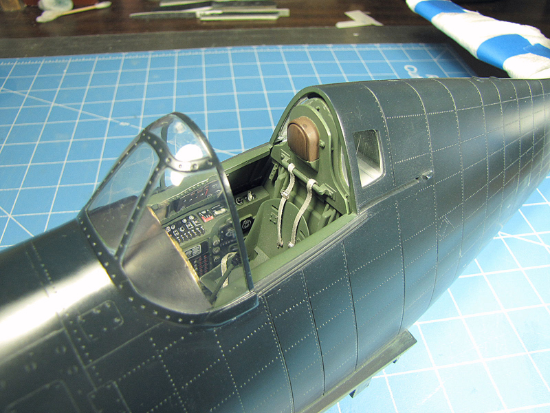
It´s time to dry fit in the finished cockpit tub and taped it in place with the green tape. I then dry fit on the center wing section, including the cowling. Everything fit ok, so I removed the cowing and wing section. I carefully removed the green tape and then glued in the cockpit tub. One photo shows the cockpit in place including the windscreen dry-fit onto the model with some white glue.
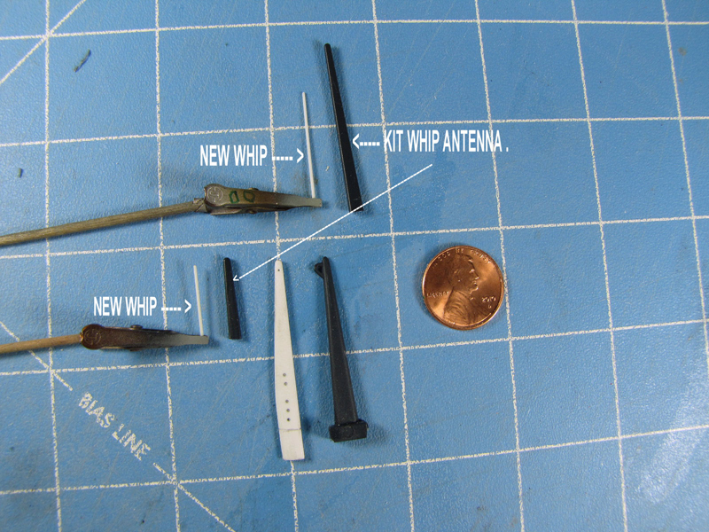
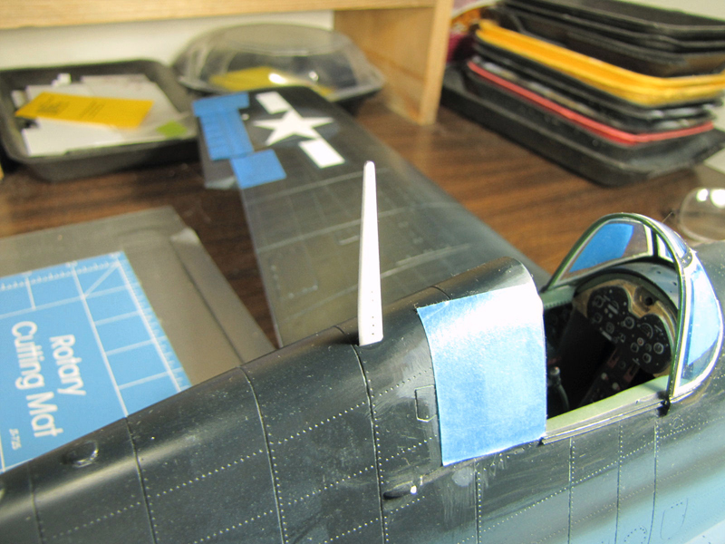
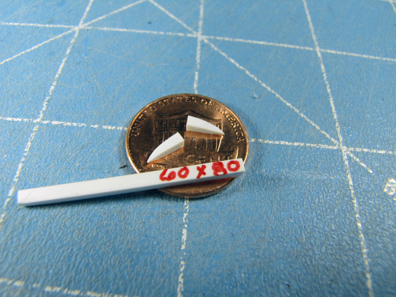
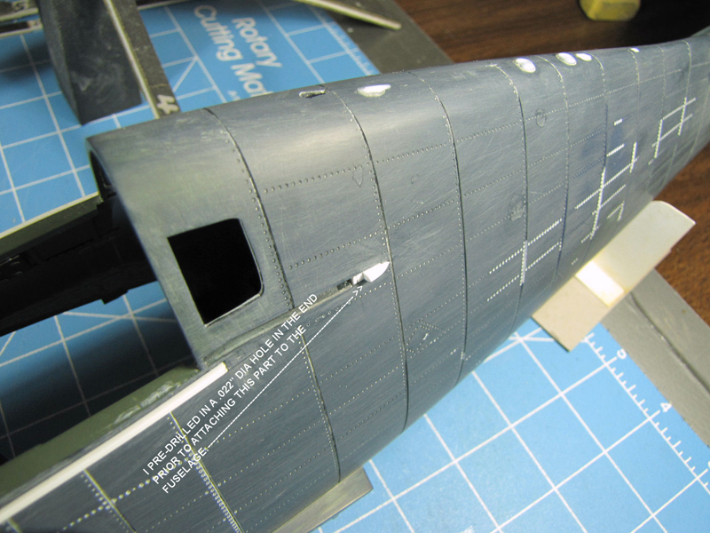
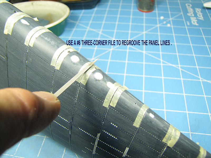
I made some new whip antennas, including the main fuselage antenna post. Then I made some other brackets to hold the canopy´s sliding cable. Some panel lines were re-scribed into the top side of the aft section of the fuselage.
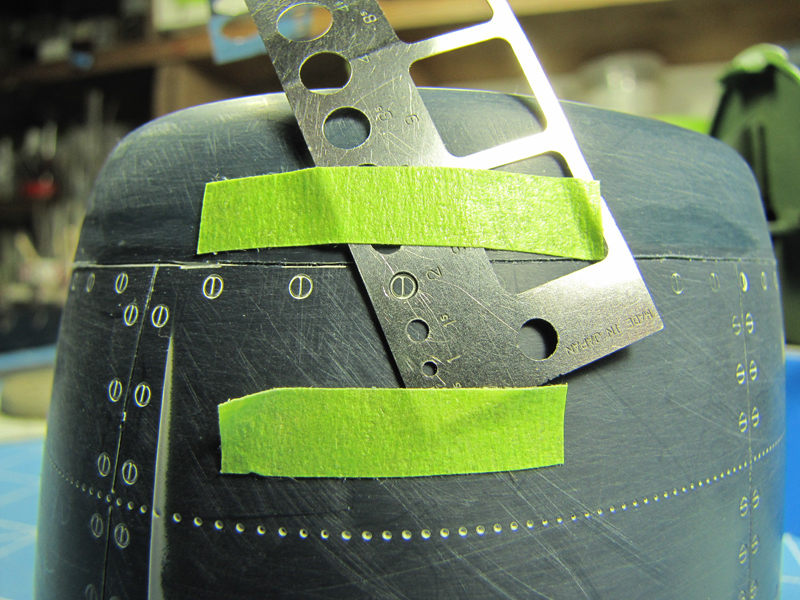
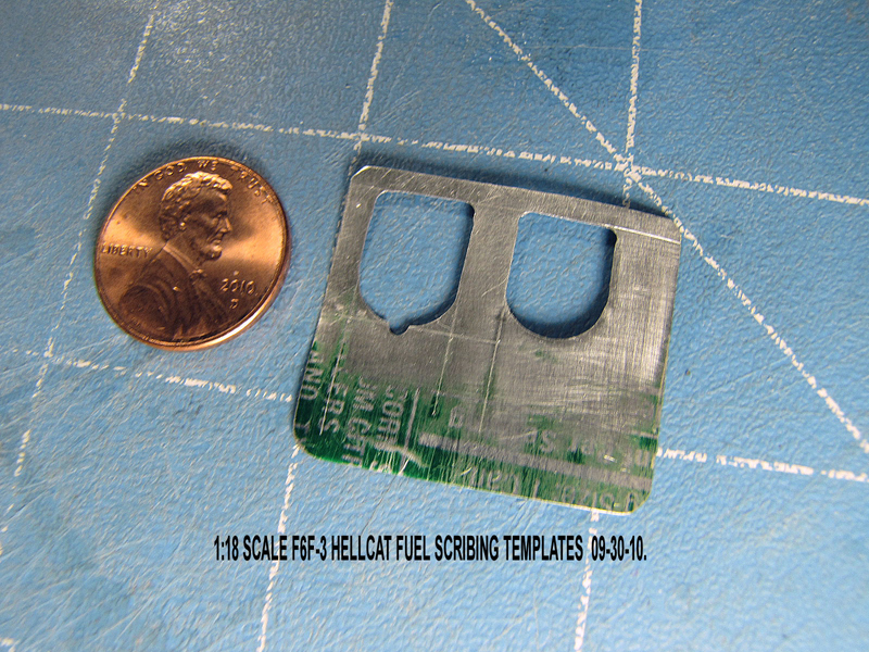
I had to curve the two 90 degree angle divider plated on the cowling´s intake. I made some scribing templates for the fuselage fuel doors as the company forgot to make them on the model.
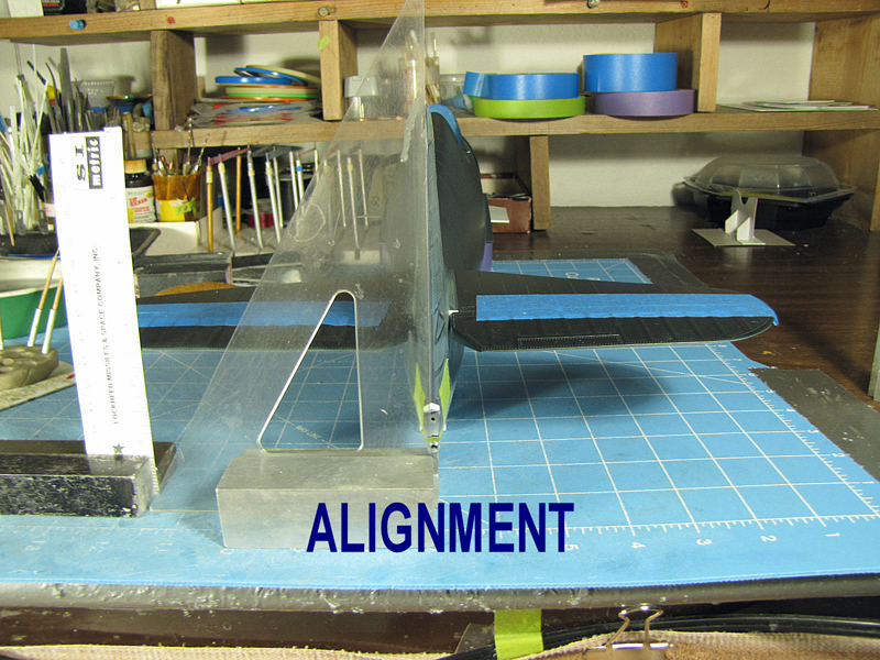
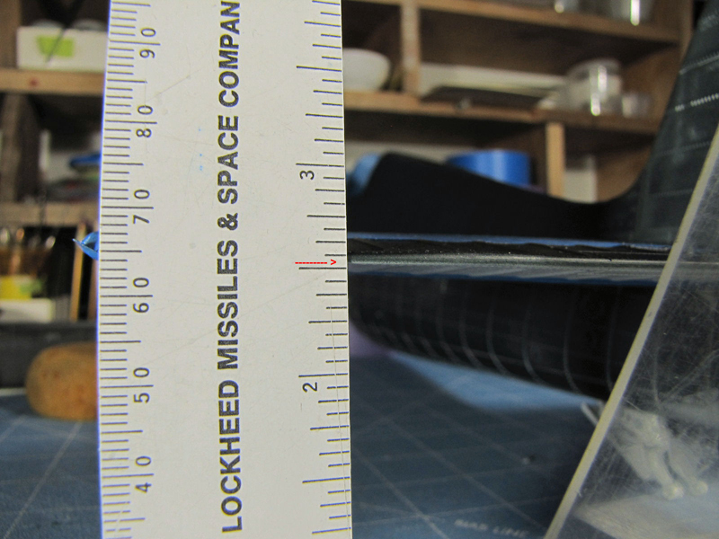
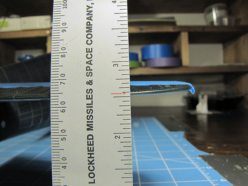
I dry-fit the two finished stabilizers to the tail plane. They had the movable elevators attached to them. I taped the movable rudder to the fin and then propped up the model and aligned it to my 90 degree angle clear plastic tool. Using my plastic ruler I adjusted each stab to meet my red mark on the ruler and then added my super glue.
REMEMBER: alignMENT...
All done, so what is next?

Part 1 | Part 2 | Part 3 | Part 4 | Part 5 | Part 6 | Part 7 | Part 8 | Part 9 | Part 10 | Part 11 | Part 12 | Part 13 | Part 14 | Part 15 | Part 16 | Part 17 | Part 18 | Part 19 | Part 20 | Part 21
© Rodney Williams 2010
This article was published on Wednesday, July 20 2011; Last modified on Saturday, May 14 2016