
Elite Forces 1/18 F6F Hellcat Part 11 - The Engine
By Rodney Williams
Revising this kit engine was a big challenge, however I did it once before on the 1:32 scale Hellcat back in 1999.
I have had a PhD in Mechanical Engineering since 1945, so I just click on: "How To Do This Job."
A reply came back real fast and it said the same old thing: Trial and Error.
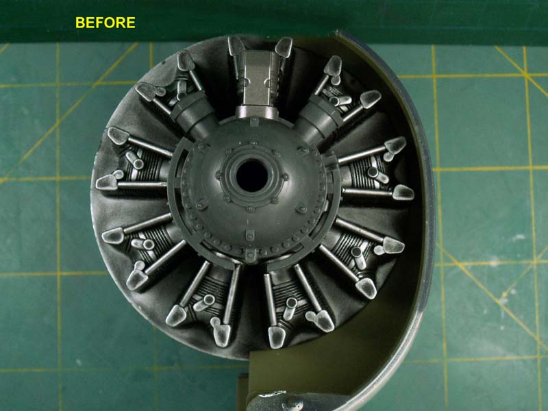
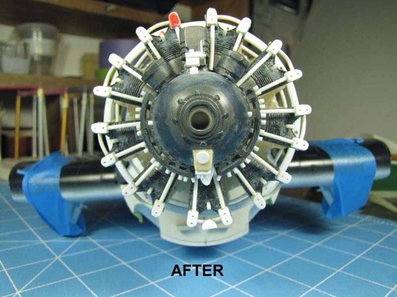
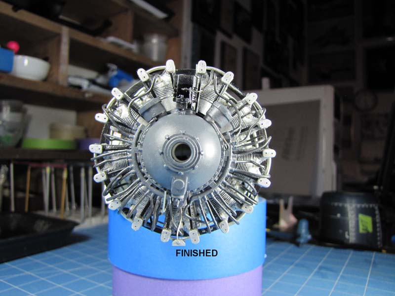
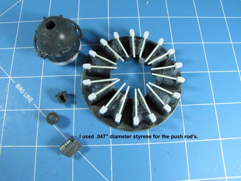
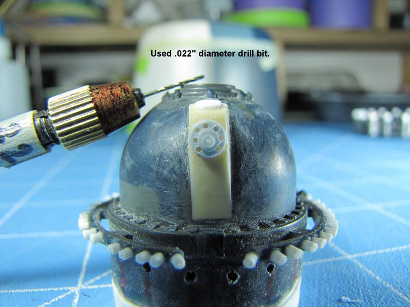
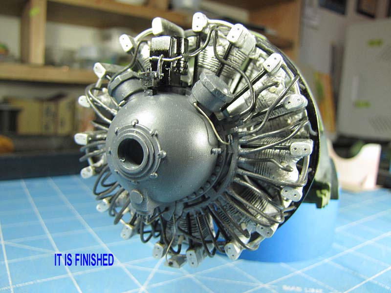
I open this story up with three photos showing the front of the engine "BEFORE, AFTER and AFTER" again. IT´S FINISHED.
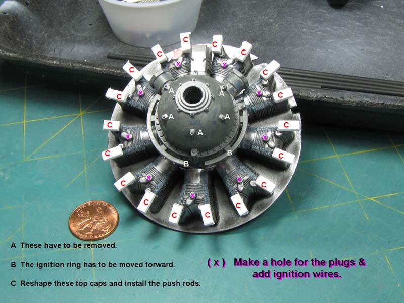
I cut out the front gear housing including the removal of the 2 magnetos and the other item that sits on top of the gear housing.
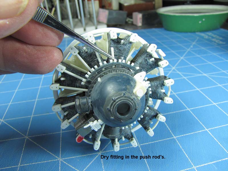
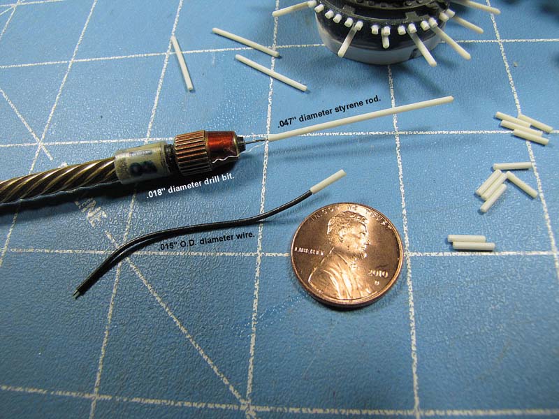
The photos more or less tell the story of how I added styrene to the front of the cylinder caps then I drilled in .047" diameter holes then dry fit in some pre-made .047" round styrene push rods.
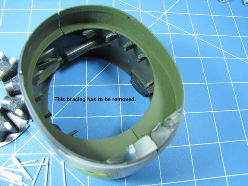
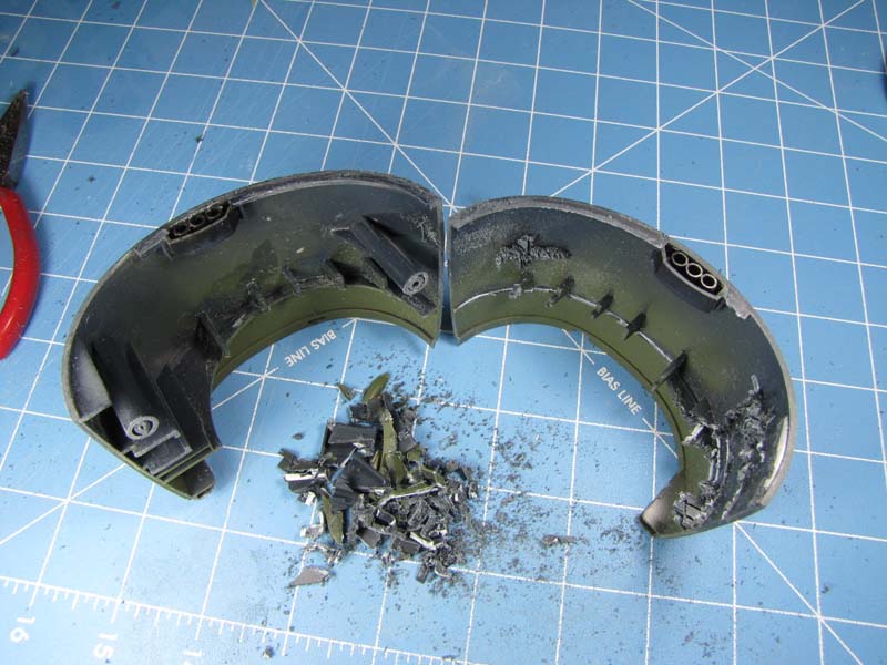
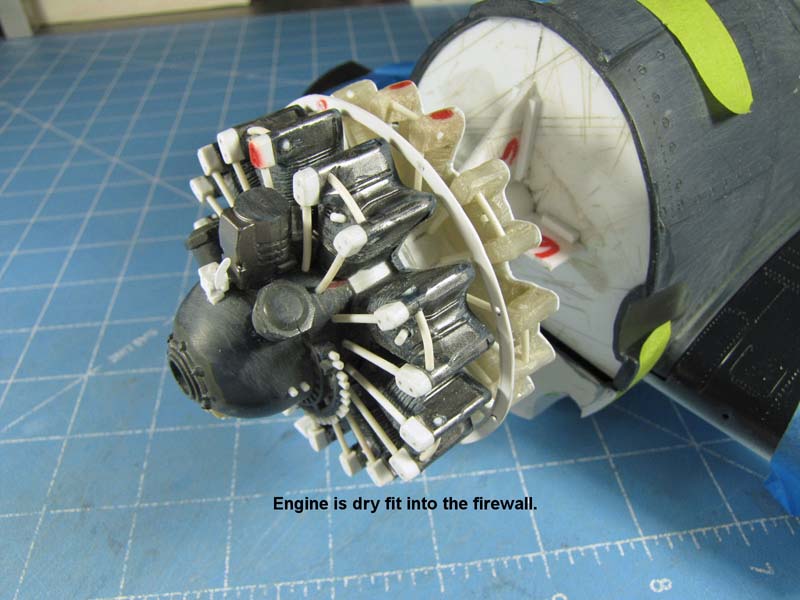
My revised engine would be installed into a built-in firewall thus I had to remove all of the frame work that was inside of the cowling as the cowling would slip in over the engine.
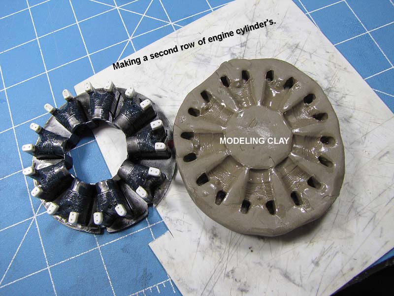
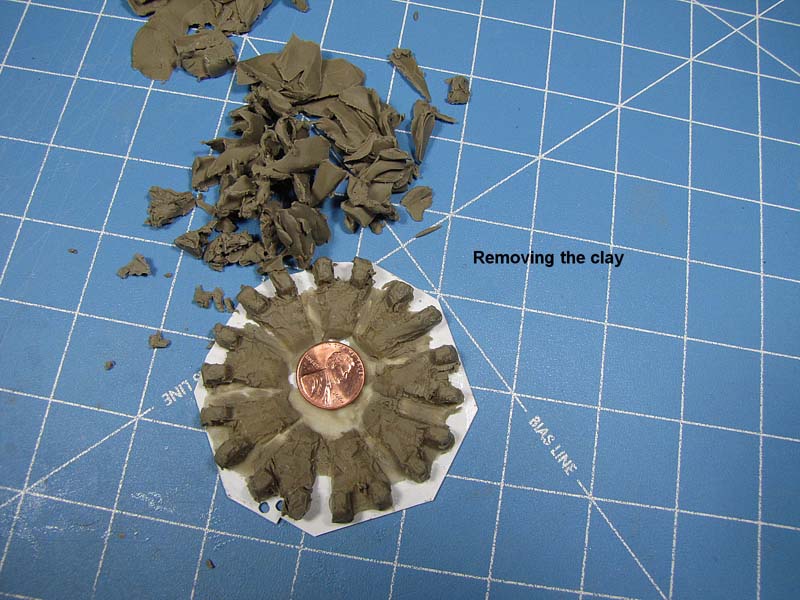
On many occasions I have use my artist sculpturing clay for molding material. I play with the clay in my hands and roll it around and around until it gets what I call "hand-warm" then place it on my .060" thick flat sheet of styrene. Next, I apply some "3-IN-ONE" thin oil to my master part and gently press it into my clay. Carefully I remove the part and let the mold get back to regular room temperature.
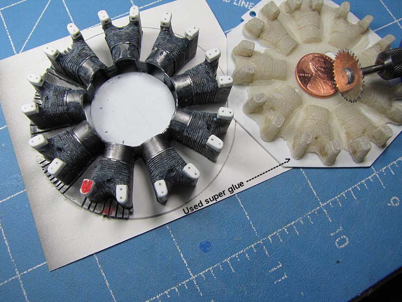
I use any brand of thin super glue and fill up the mold. After the glue is good and dry (2-3 days), I cut off most of the clay and then I place the cast part into a container that has been filled with ordinary paint thinner, (Mineral Spirits). I let the parts soak in the thinner for a half hour or so then I use a stiff bristle brush and brush off the clay. I then wash the part in soapy water and again wash it with denatured alcohol.
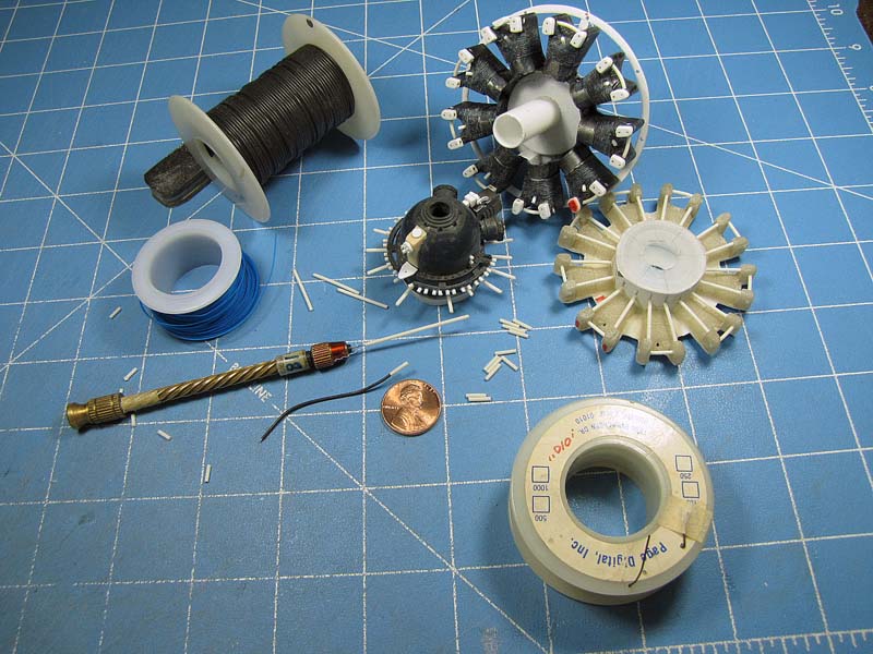
I glued the new row of cylinders to a .030" thick flat section of styrene. I will trim off the excess glue around the cylinders and drill in the spark plug holes.
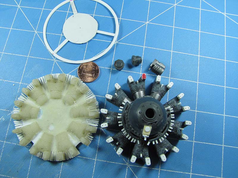
There is some sort of black ring attached to the engine between both rows of cylinders so I make it out of some more flat sheet styrene.
You will note that I have placed some red ink marks in certain places on my parts. These represent my alignment marks. Alignment is basic and is a most important part of model building.
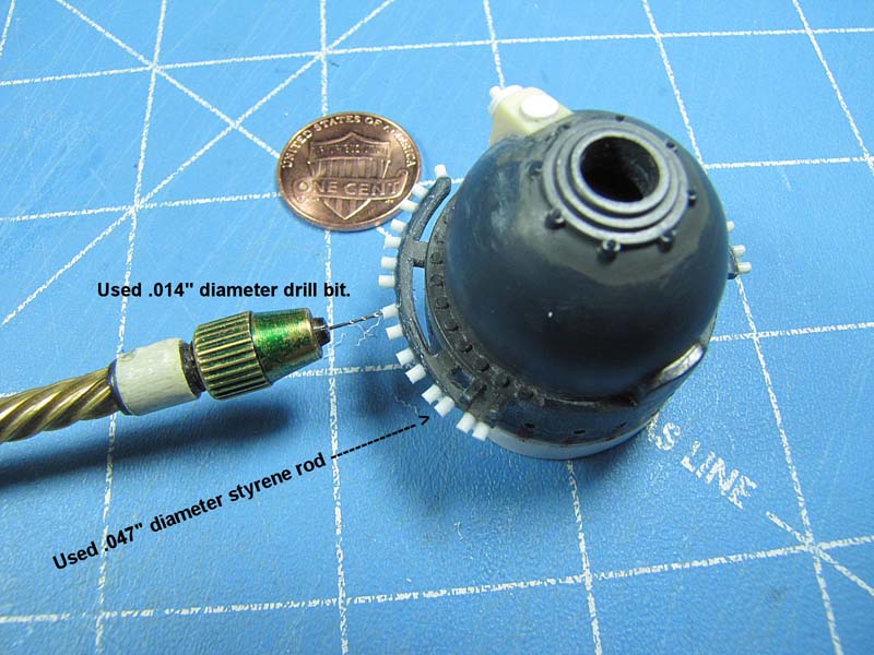
I have added some additional styrene to the back side of the round gear housing.
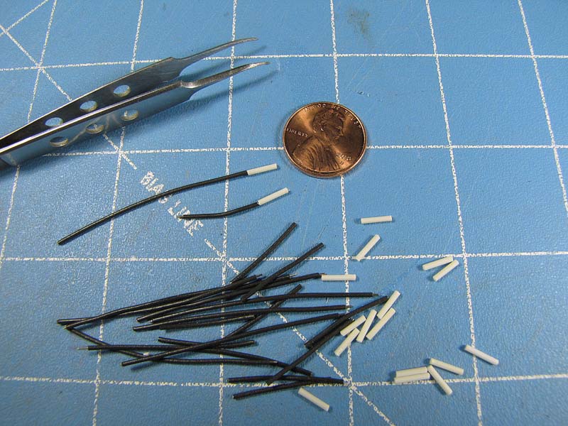
I cut more short sections of .047" diameter round styrene rod which represents the small stub-outs that are on the ignition ring. I drill in .018" diameter holes into these little parts, which will receive the ignition wires.
I build in the lower item that is seen on the real engine gear housing by using some left over cream colored cast resin stock.
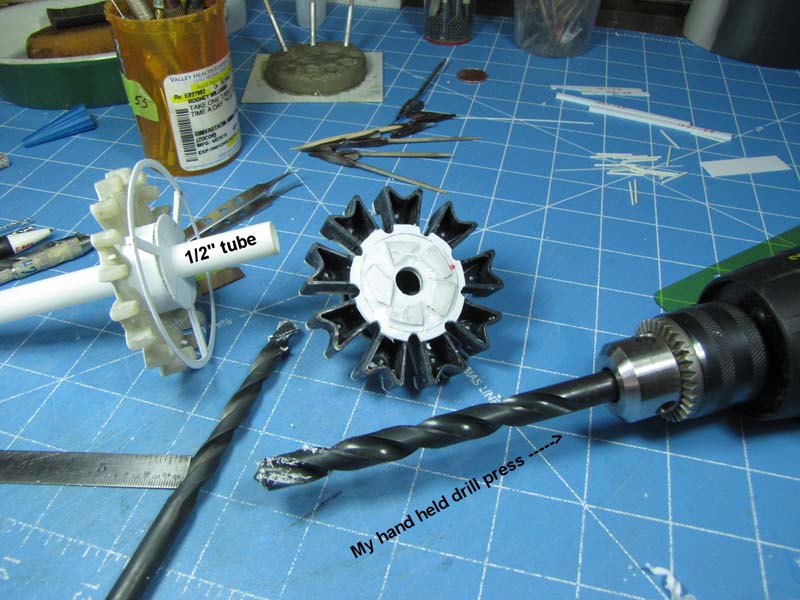
I add a backing plate to the front row of cylinders and a front and back plate to the second row of cylinders. I then click on my brain's PhD "pc" and ask myself:
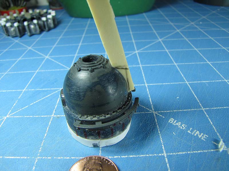
Hey Rodney, why not make some holes in the plates and shove in a ½" round tube and put the two banks of cylinders together, including that large pre-made round ring?
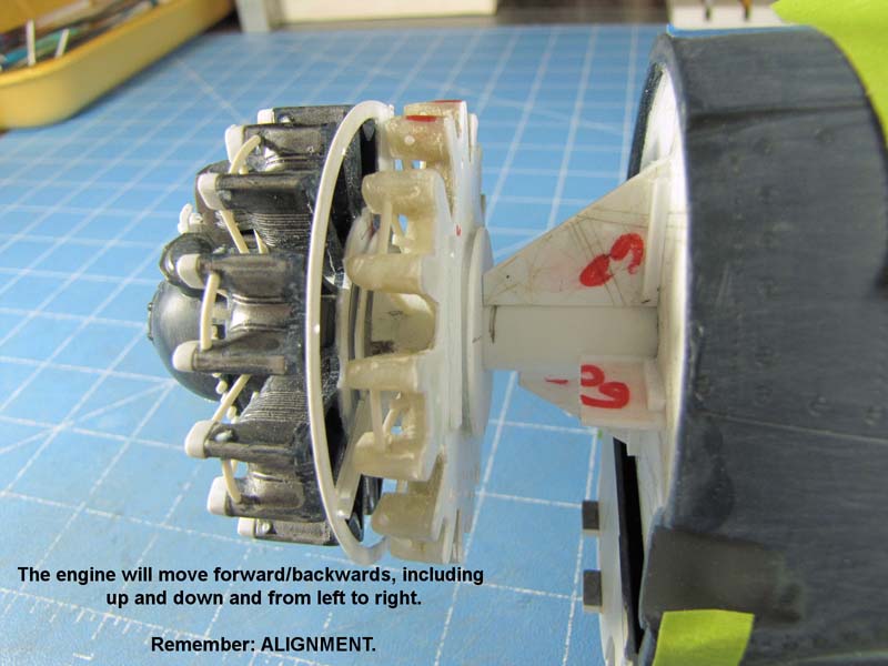
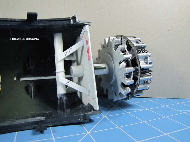
It works out A-OK, so I drill in a hole into the pre-installed .060" thick firewall. I brace the firewall hole with some thick styrene, which is a bit loose. When I slip in the tube, this extra bracing let me move the tube from left to right, up and down and in and out. This is extremely necessary for perfect engine alignment with the cowling.
Now you most likely will ask: How will you glue the engine shaft to its bracket, once you glue on the cowling and glue on the center wing section.
Answer: I´ll show how to do it in another story.
I have cut several sections of soft .015" diameter insulated wire so I can use them as my ignition wires, etc. I just drill in .018" diameter holes into my pre-cut spark plugs. This slightly over size hole lets me push in the wire fairly easy after all of the parts have been painted. As you would guess some paint gets into the holes.
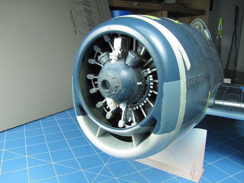
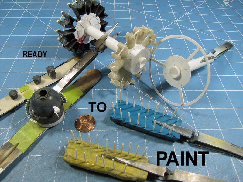
Everything is ready to paint. I use my flat Tamiya dull silver paint for the cylinders and their semi-gloss black paint for the push rods and other parts. I have chosen Tamiya XF-24 Dark Grey for the gear housing and once it is dry I brush on some SnJ aluminum polishing powder to represent some weathering around the bolts etc. I just add a bit of Future Floor Wax on top of the gear housing. It takes this old man with the "shaky-hands" over 5 hours to install all of the ignition and other wires into their proper places.
IT´S FINISHED!
My next segment is: "THE CENTER WING~III".
Until then it´s happy modeling time.

Part 1 | Part 2 | Part 3 | Part 4 | Part 5 | Part 6 | Part 7 | Part 8 | Part 9 | Part 10 | Part 11 | Part 12 | Part 13 | Part 14 | Part 15 | Part 16 | Part 17 | Part 18 | Part 19 | Part 20 | Part 21
© Rodney Williams 2010
This article was published on Wednesday, July 20 2011; Last modified on Saturday, May 14 2016