
P-51D Miss Velma in 1/18 Scale - Part 3
By Jay Wheaton
Welcome back again to the 1/18 21st Century Toys Miss Velma P-51D re-build. Part 2 took us to the near completion of the cockpit. Now I will show the conclusion of the cockpit build, the canopy and windshield, plus the start of the wing work.
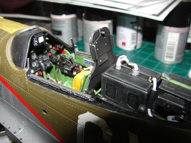
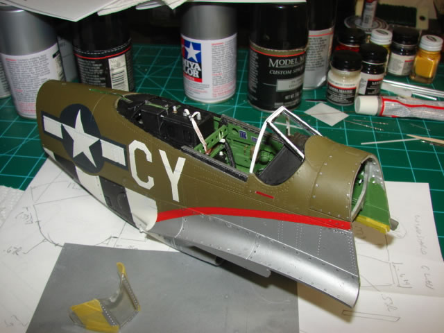
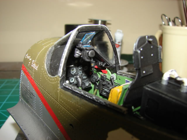
Here is the completed cockpit (except for the gunsight which goes on after the windshield is in place). So when we last visited the cockpit, some things remained to be done – gunsight, control stick handle, heater ducts, rudder pedals, and canopy rails. The gunsight and its mount were interesting little projects. The mount was fabricated from sheet plastic and had to mate up properly with the scratch built instrument panel shroud. It took a couple of tries to get it right. The mount is the N-9 variety, as opposed to the K-14 mount which is a little different. So I had to pay attention to drawing definition. The N-9 reflecting gunsight was original equipment for P-51Ds until later versions when the K-14 computing gunsight was used. And the K-14 was so effective that it was retrofitted to many older aircraft in the field. I have a late war picture of Miss Velma which seems to show the K-14, but I am trying to show her earlier in her career when she would have had invasion stripes, and I am sure that at that time she had the N-9. You will also see the canopy rails. Oh man…these parts tested my patience as much as any others, mostly the perforated side plates. They are made from .06 wide by .01 thick plastic sheet, with 20 carefully drilled holes and 6 carefully shaped slots, all 26 penetrations almost as wide as the stock material itself. So fragility was the issue – I made and ruined many of these, often late in the process, until I finally got three (two sides and one in back) which didn’t break. I can only believe even the real steel parts were fairly fragile. The channels for the tracks are made from brass channel section, the only material I could find that was near the right size shape. Fragility was definitely not the case for these parts. They were tough to cut and tough to drill – I used up several drill bits on them. In the end I was very pleased with both the canopy rails and the gunsight mount. The heater hoses which hang off the shoulders of the armor plate do not show up well in any of my pictures, and are hard to see even looking for them except their outlet fittings. I spent way too much effort on them, making them out of solder similar to how I made the oxygen hose. Enough said about those disappointing parts. Rudder pedals got a ton of work also – too much for parts that are only seen if you are looking for them with a flashlight. I wish I had a picture of them for you. And let’s not forget the control stick handle which is visible in the picture, made from what? Thick plastic stock! It turned out great.
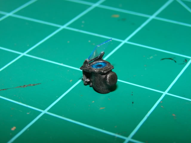
The N-9 gunsight was made from several sizes of plastic tubing or block and some clear plastic sheet for the glass, and benefited from a very neat computer model. I thought this part would be difficult to make, and my backup plan was to go to the more boxy and supposedly easier K-14. But to my surprise this part fabbed up quite well. To design it on the computer I really had nothing to go on except web photos and some fuzzy old artist renditions of the gunsight from a NAA process manual on the N-9. But it seems to be scaled it about right. Once done, it would wait until the windshield was installed before attachment to its mount.
The canopy was a large project and frankly lots of fun (you should get the idea by now this whole re-build was lots of fun). Some with outrageous skills would have made a mold and vacuformed a more accurate canopy. Not me, I don’t have those skills; so I just used the existing part. It’s shape, although kind of sexy to me, really isn’t quite right regardless of what kind of D-model canopy it is compared to (there were several). Miss Velma had a “California -2” canopy, just like all the earlier D models. And the 21CT example is probably intended to resemble a later version which was more bulged on the sides, presumably to improve all-around vision. On top of that, it has some other problems – it is a little “over-blown” meaning the sides bulge enough to spill onto the canopy frame. That shouldn’t be and it appears to be something copied from the old 1/24 Trumpeter kit. It also has a large hole on top for the Detrola radio’s aerial antenna, and it is a bit misplaced. And if the canopy is slid back to the opened position, or even partially opened, the aft end of the canopy stood up in the air, rather than lying down on the top of the fuselage as it should. Just about all P-51 kits have this malady. I had to live with the canopy shape and the position of the hole, but I could fix the open position issue.
Recall that I had built up the canopy deck by about .08 inch. So first was the heavy sanding and thinning of the canopy frame. I simply sanded it down that .08 inch until it once again matched the windshield. This left the lower frame a little too shallow looking, but I corrected that later when I masked off the glass for re-paint. Then the inside surface of the lower frame was scraped out to reduce thickness along its lower edge, enough so that the canopy would lie down properly in any of its open positions. It got pretty thin in spots. Now the canopy would be ready for its internal framing. It isn’t that easy to see in the picture above, but the canopy received a fairly elaborate internal framing that gave it some thickness, two authentic looking angle brackets to attach the curved beam, and an aft deck with a seal which mates up with a frame on the fuselage canopy deck. All were made from simple plastic sheet, with trial-and-error shapes. And on that internal framing I attached a rather crude representation of the roller bogies. These fit over the canopy tracks on the fuselage and align the canopy. The kit’s inaccurate curved beam, which spans the sides of the canopy and is highly visible, was replaced by a scratch built unit. I subjected it to computer modeling with the simulated radio and battery to make sure it would clear the them with the canopy in various positions – there were enough unavoidable inaccuracies with many of the parts involved (to account for errors in fuselage shape, thick gages, etc) where I had to make sure. So it clears and then some – I could have lowered it a touch. The beam is made from thin plastic sheet with several drilled lightening holes, and glued-on flanges. The large hole on top of the canopy needed to be covered since, as previously mentioned, this aircraft did not have the Detrola radio equipment. In the ETO a clear plastic cover was added by a Tech Order (TO) or something like that. I found the paperwork and drawings for the part with the help of some members of the P-51 SIG, and made up a replica out of thin clear plastic. The last part of the project involved the three mirrors and their mounting brackets. Many 55th FG aircraft had interesting field mods for their rear view mirrors, perhaps none more interesting than those on Miss Velma. They can be seen in the period photo in the above picture. She had three on fairly crude sheet metal brackets – clearly the pilot wanted to have a fully visible six o’clock. My 1/18 brackets are thin and fragile plastic, and the mirror housings are made from .218 inch plastic rod, sanded and filed to shape. I punched out some mirror glass from aluminum foil and attached them to the housings. After all that work, I figured it would be only a matter of time before I broke one or more mirrors off, but so far they are still intact.
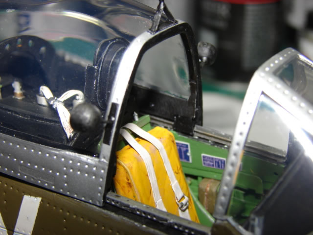
This picture shows the canopy on the tracks and gives you a feel for what I was trying to accomplish. You can see the canopy’s internal frame build-up, the little flap that represents the roller bogie that fits nicely over the track on the canopy deck, and a lot of other cockpit detail. Never mind the kit’s original windshield you see there – that is soon to be replaced. The canopy can be positioned anywhere along that track and the fit is pretty good.
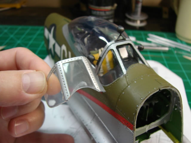
So about that windshield – this part has a big deep blemish where it was glued to the original IP shroud, made worse when I pulled the fuselage apart early on. I spent an undue amount of time sanding and buffing it to try to get it to look acceptable, with no real success. It was at this point that I decided to try a rather outrageous scratch build project on the windshield, just to see if it could be done and if it made an improvement. I would keep the old part around in case the project was a failure. I had two great enablers which would give this scratch build a chance – computer modeling, and single curvature of the side glass. By that I mean not compound curvature – one can roll a single curved piece of thin clear plastic into shape; not possible for a part with compound curvature. The side glass on the P-51’s windshield is either single curvature, or close to it.
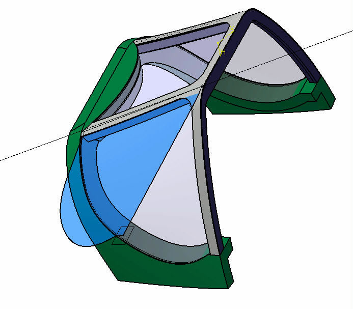
The computer modeling was not easy to get right, because I had to approximate the existing fuselage’s shape and curves in 3D, and most importantly the shape of its circular cutouts for the three clear panes. Also I had to make a good approximation of the curvature of the aft frame, which would have to closely match the canopy. At least that part was easy – I merely traced the outline of the aft edge of the existing windshield onto paper, and created a similar curve on the computer. You can see in the picture above the 3D computer model with its simulated fuselage portion, windshield frame parts, and the “glass” parts. The side glass is unrolled onto a plane, giving a flat pattern that I could scribe into clear plastic sheet. Then I would roll it around a round object (an Xacto knife handle) to try to give it a reasonably accurate shape. Then the framing could do the rest of the shaping, in theory.
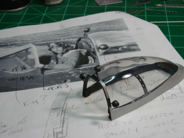
Critically important was the windshield frame, shown above prior to insertion of any clear parts. I just had to trust the digital model and cut frame segments to size from plastic sheet or rod. The aft frame had to match up with the closed canopy with its shape and its angle to the canopy deck, and this was difficult to do exactly. There was lots of dry fitting, but at least some assembly gluing was required to do the dry fitting. Thanks to the digital modeling there was not much starting over though – the original parts pretty much worked.
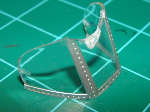
Here is a shot of the completed windshield. The side glass was made as described above by cutting out a flat pattern on .015 clear plastic sheet and roll forming it, doing final trims after much dry fitting, and carefully gluing it to the framing and fuselage cutout. The front bullet proof piece is actually two sheets of .010 inch clear plastic sheet separated by spacer frames on three of the four sides (not the bottom curved side). This gave it its thick look; in real life it was 1.5 inches thick. Once the “glass” was in, I covered the edges with a 5-piece frame covering (four legs and a central piece) made of .01 plastic sheet, and carefully cut to the right shape. That is largely how it was done on the actual aircraft. This frame was great – it meant no masking required for frame painting, it covered up any little gaps or other imperfections on the edges of the “glass” parts, and it was easy to generate the right shape, which is so often misrepresented on P-51 models including the 21CT model. To me, this effort was the climax of the entire effort to date. I had been sweating it for quite a while, and what a thrill it was to have this outrageous idea actually work.
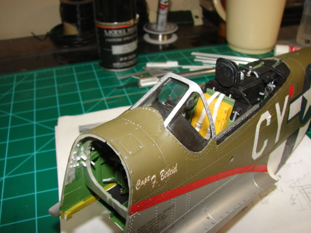
This picture shows a view looking forward, and the gunsight is now in place. The curvature of the side glass is in evidence here, as well as the completed aft frame.
And lastly a comparison shot with the original 21CT part – if the scratch build had failed, the old part would not have been the end of the world I suppose. This shot also shows the match between the canopy and the windshield which is pretty good, but not perfect.
At this point some 15 or 16 months had transpired, and only the fuselage and landing gear were finished. The wing loomed large so it was time to put a plan together. The 21CT wing has lots of serious problems that need addressing if it is to be an accurate wing: 1 - its span is too short by around .25 inch per side, 2 - its flaps are terribly inaccurate, 3 - the wings are warped at about 2/3 span both sides giving a slight coke bottle shape when viewed on edge, 4 - the wing dihedral is too small (should be 5 degrees per side), and 5 - the wing chord is too short at the fuselage and at the tip. Also, and it goes almost without saying – the wheel well needs to be re-built entirely. The wheel well rebuild is sort of expected for all P-51 kits except the new 1/32 Tamiya, if for no other reason than to give it an accurate front spar and LE ribs. This plan would correct almost all the wing issues; a couple would remain – the D-model specific extended leading edge between the root of the wing and the landing gear (the B-model didn’t have this feature) is actually not extended enough, and the wing leading edge shape is too blunt. I would live with these inaccuracies; the LE extension shortness would make life interesting later in the wheel well. To address the span shortness issue, I would saw off the existing wing tips and make wider ones – this would get me nearly there; close enough. To address the wing chord shortness issue, I would cut off the ailerons and throw away the flaps and replace both with new scratch built units with the right chords. They needed replacing anyway. Mismatch with the side-of-body fillet fairings was a non-issue because the flaps would be shown deployed in the down position. And the new wing tips would have the right chord to match the new ailerons. To fix the warp and the dihedral, I would give the wings stout front and rear spars which would re-shape the wings. The new front spar would also serve as a key component in the wheel well re-build. This turned out to be a pretty good plan, but a very difficult one to execute.
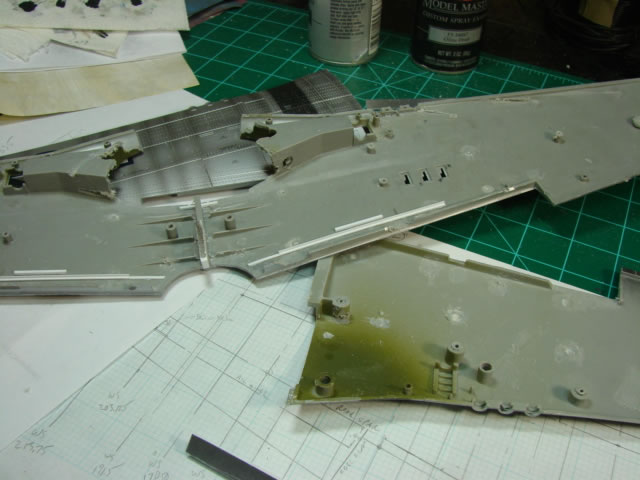
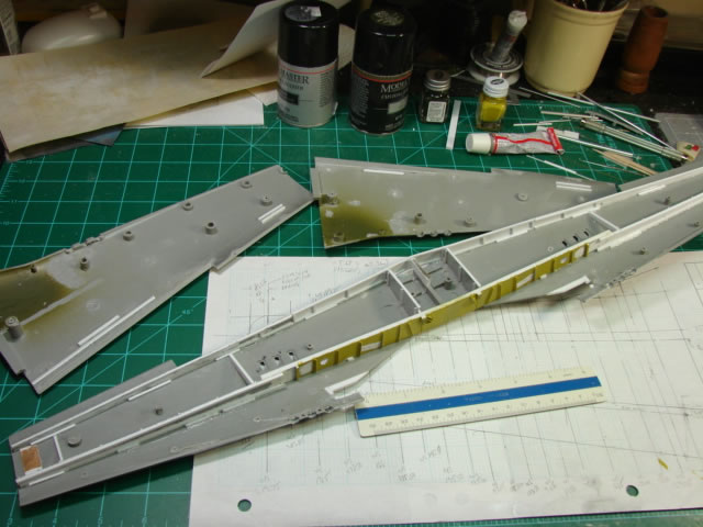
The fuselage was difficult to break apart; the wing was nearly impossible to break apart. It is just amazingly stout, and once again I subjected myself to possible maiming while cutting and sawing and prying. But it got done without damaging myself or the wing parts - be careful if you decide to do this. What you see above are the separated wing parts being prepared for spars and a few stabilizing frames and/or struts. The wheel well is partly Dremeled away, as well as most of the columns for attaching the wing halves together; a little later the whole wheel well would disappear. All this stuff used to control the thickness of the wing; now the spars would.
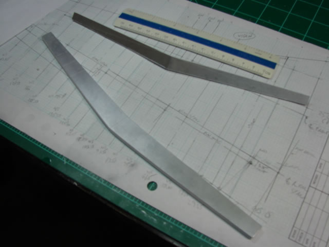
This model’s wing span not including the tip fairings is about two feet. That is how long the spars need to be. I did not know where to get my hands on spar chord material that long, so I chose to splice the spars into three segments – a middle segment, and two outboard segments. It may be that having one LH and one RH segment would have been better. I will never know; I felt that a single middle segment would hold dihedral the best. The take-home point is that the existing wing pieces are heavy and thick and extremely stout, and do not take kindly to being re-shaped. Any spar you put in had better be very strong. What you see above are the front and rear spar middle segments only. They are made from plastic sheet webs and ample section plastic rod for the spar chords. In back (not shown) are vertical stiffening elements to stabilize the spar webs – much like a real airplane wing spar. The vertical stiffeners were essential to prevent the webs from crushing or buckling once installed to the lower wing piece, and then forcing all three major wing parts into the right shape. Both segments have accurate kinks at their center lines, the front spar with a very slight but perceptible kink, and a much more pronounced one for the rear spar.
So here is what the major structural elements of the re-built wing look like, with some angle stiffeners and scratch built fittings added to the front spar forward face (which will be visible in the wheel well). Note there are a couple of support ribs between the spars, some stabilizing struts, and the spar center segments have been spliced with their outer segments. The outer segments were made similar to the center segments, with some engineering of the splice areas. They fit just fine the way I did it, but it turns out the splice area was a bit weak, as well as the outboard spar segments themselves, and were not able to completely overcome the warping. If I were to do it over again, I would either have two-piece spars joined at the centerline with much thicker material for the OB most portions, or stay with the three-piece arrangement and greatly beef up the splice areas, increase the distance of the splice overlaps, and use thicker material for the outer segments. Incidentally, the wings dihedral was corrected perfectly as far as I can tell. This picture also shows the revised edge trim of the lower wing cutouts for the strut mounted LG doors (in white). This was done after the complete removal of the existing wheel well material.
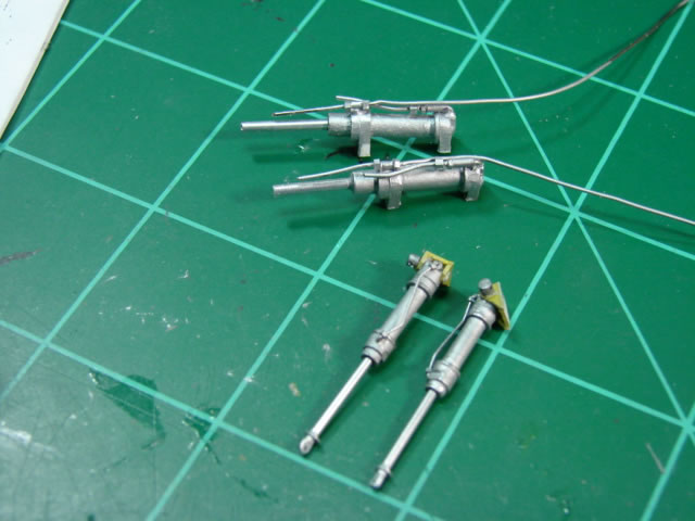
At this time I needed to make the LG actuators which are nestled between LE ribs just inboard of the LG posts. Also for some reason I decided to do the LG door actuators as well – the latter parts are easily seen in the wheel well and needed to be done well. The outer cylinders are made from plastic tubing. The end caps are made from either thin metal or plastic tubing. And both have hydraulic lines made from solder or wire, and microsurgery fittings and nuts. The inner cylinders, or piston rods if you will, are just plastic rod with aluminum plate paint buffed to a shiny finish (at least on the door actuators). On the LG door actuators, the rod ends are just the rod material squashed to shape with a hole drilled in the flat for the attach bolt, and with jam nuts and washers added. More difficult were the chromate yellow mounting brackets for the LG door actuators, and the combination pivot pin and hydraulic fitting. These brackets will attach the actuator to very cool fittings on the front spar, much much later. The LG actuators on the other hand would be installed very soon.
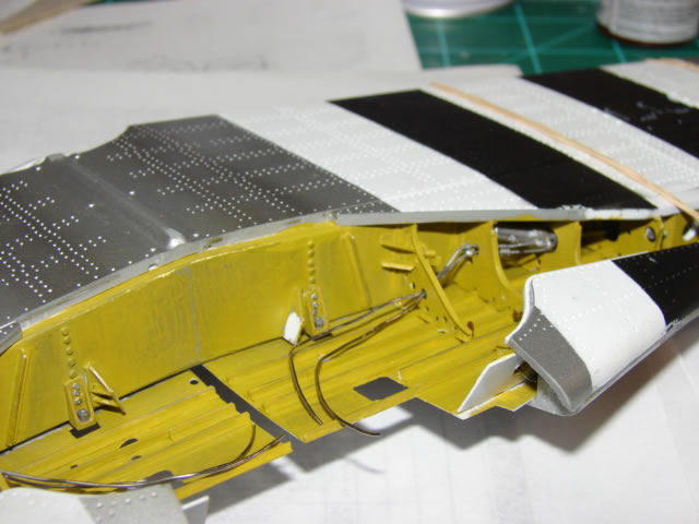
This picture shows the first significant progress in the wheel well. You can clearly see on the front spar and its “bathtub” fittings for the wing attach to the fuselage, and fittings to mount the LG door actuators. Both are made from simple plastic sheet. Much more involved are the LE ribs, the new upper wing skins with angle or tee section stringers, and the LE false spars. You can also see the right hand LG actuator mounted on the front spar, with hydraulic lines partially routed through holes in the ribs. Just on the right hand edge of the photo you can barely see the LG mounting casting (the part with the large hole). It is basically a box made from about .03 or .04 inch plastic sheet. It and a hole in the spar itself make for a very stout LG attachment.
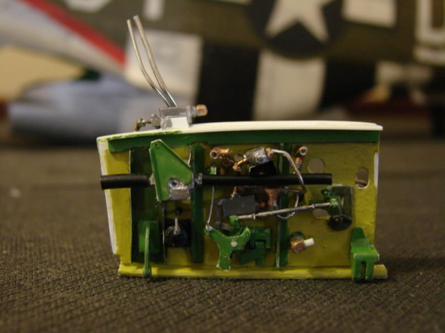
The kingpin of the wheel well is the centerline bulkhead, which has more gadgets per square inch than anywhere else on the model, including the cockpit. This area of the well got a very detailed computer model and it was sorely needed. The rib is not quite as long as it should be due to the overly short leading edge extension, so there was some crowding that had to be done. Some of the gadgetry shown on the LH side above includes LG door hinges, fuel shutoff valve with hoses, LG door timing bellcranks and linkage, hydraulic check valves, fuel line bulkhead fittings, and hydraulic lines. The centerline bulkhead was about a month long project.
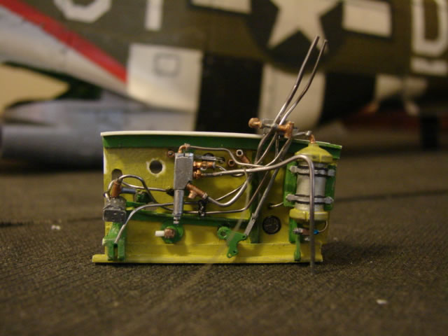
Here is the RH side of the bulkhead, nearly finished. The large canister at its right end (forward end) is the hydraulic accumulator and just aft of it is its pressure gauge. Hydraulic line routing (solder) is done compliments of an excellent engineering drawing which shows every hydraulic line in the wheel well if you are willing to study it long enough and color code it. The two large holes on the aft portion of the bulkhead are for fuel lines which will be fitted after the bulkhead is installed in the wheel well.
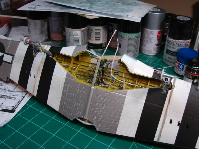
This shot shows the LG bay about as complete as it can get without the wing being installed on the fuselage. The main LG struts are installed, as is the centerline bulkhead, LG door actuators, fuel selector valve and bracket on the spar. And lots of lines are in place some of which have loose ends waiting to be attached to the cockpit floor forward of the rudder pedals. System runs include wiring harnesses made of bundles of thin gauge wiring painted white, three different diameters of hydraulic lines (using .015, .022, and .032 solder), fuel vent lines, fuel supply lines, fuel hoses (made of wiring insulation), and bomb control cables and LG door sequencing cables (fishing line). There are many many hydraulic couplings each with nuts on either end. It was here where, to maintain my sanity, I quit making nuts from scratch and bought dozens of metallic nuts from Scale Hardware. I represented every system in the wheel well except the pitot static line on the front spar (I found out about it too late).
The wing was also painted at this time. I did not fill in rivet depressions, an omission that I regret. I wish I could take that back. Painting was not a big deal, except the stars and bars. Similar to the fuselage, they were painted and that is just a difficult job to do well.
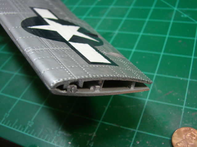
With as much done in the wheel well as I could do, I turned to other things. Recall the wing tip needed to be replaced to add more span, and match up with a larger aileron still to come. First I sawed off the existing tip at its panel line as shown. You can see the ends of the front and rear spar exposed. You can also see the difficult painted insignia. White went down first, followed by blue over a star and bar shaped mask, followed by silver over a complete mask with a circle shape and the bars.
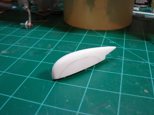
Here is one of the wing tip details made from a very thick chunk of plastic, actually three layers of plastic, shaped in three directions with saw, Dremel and file. Note that I have added a bit of width to its base to lengthen the wing span a little more, part of my original plan for the wing. This part and its opposite took long hours because so much material had to be removed, and getting the shape right (or near right) was a painstaking process of sand/file a little, test fit, sand/file a little more, test fit, on and on. I had done this on the tail surfaces also, but they were smaller and easier to work with.
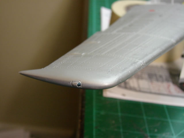
And voila – the new finished wing tip with a fancy little tip light. The other side’s light is red of course. The new tips’ attachment to the wing was coarse enough to require a good bit of putty work, and then restoration of panel lines and the cursed little rivet dimples.
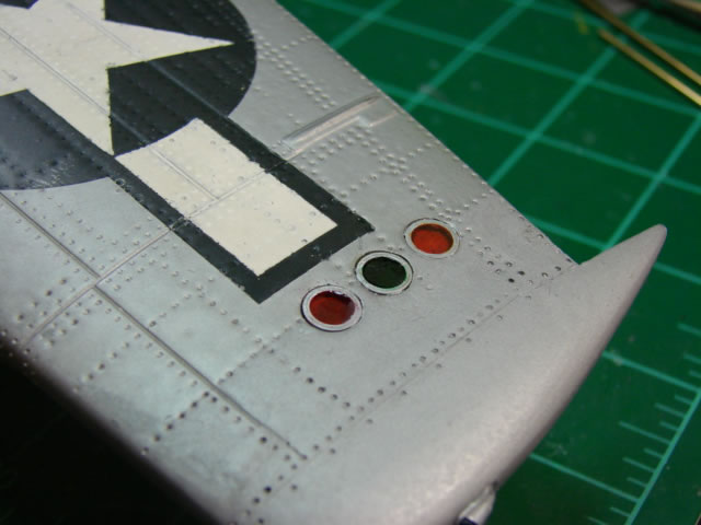
Here you see the ID lights on the bottom of the RH wing. The 21CT model has these lights but they are inaccurate in every way, even their locations. I decided not to putty over the holes and start over; instead I enlarged the existing holes to proper size, and pulled the holes as much as I could in the direction they should go. They actually should be closer to the tip. I backed the holes with plastic sheet on the inside of the wing, cut some aluminum tubing for the rings and inserted, painted the holes the right colors, and then poured 2-part epoxy in the holes to make it look like glass.
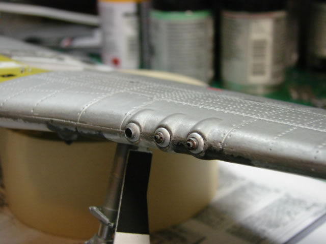
Most P-51 kits do a lousy job with the machine guns, and I am afraid the new Tamiya didn’t do that well either. Certainly the 21CT effort is a joke. I was excited about making awesome MGs, but they just aren’t as good as I hoped. The plan was good, but I made just about every mistake possible to make while executing the plan, including gluing in the wrong gun in the wrong hole. The errors were corrected, but some sloppiness and some superficial damage crept in. The components are all made from various diameters of either plastic or aluminum tube stock. The holes in the wing were reamed out significantly to accept the large outer diameter of the blast tube housings. As many of you know, each gun is a little different because the barrels protrude out a different amount from the wing LE. The most inboard gun barrel cannot be seen, even, because it is buried inside the blast tube. And that is because that gun is staggered aft relative to the other two, to allow proper feeding of the ammunition.
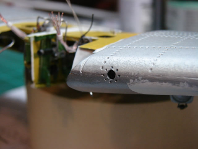
The gun camera opening on the 21CT kit is a pitiful square patch of black paint and a decal. Oh well…it’s just a toy I keep having to remind myself. First, you will find two versions of the gun camera opening on the P-51D. The later and more familiar opening is square; the earlier opening is round. I think the difference came about with the introduction of the K-14 gunsight but I am not sure. Anyway, Miss Velma needed the round gun camera opening and that’s what she got. Inside is some crude representation of the camera itself – it’s better than an empty hole. I will stop here for now. In the final installment I will show the work on the all new flaps and ailerons, the landing gear doors, wing to fuselage join, final completion of the wheel well, and the very last project – the bomb racks. I will finish with the obligatory views from all sides of the finished model. Thanks for tuning in.
Part 1 | Part 2 | Part 3 | Part 4
© 2012 James Wheaton
This article was published on Saturday, August 11 2012; Last modified on Saturday, May 14 2016