
P-51D Miss Velma in 1/18 Scale - Part 1
By Jay Wheaton
I have been inspired over the years by re-builds of 1/18 scale toy aircraft (21st Century Toys, BBI, Ultimate Soldier, etc) into some really impressive scale models. LSP has done a great job documenting several such efforts. Since my favorite WW2 aircraft is the P-51, and I had not seen anyone try it yet, I decided to give it a whirl. That was two years ago! Since then I have been on again and off again (mostly on again) working away at it expending literally thousands of hours sanding and cutting and filing heavy gauge plastic, and making thousands of scratch built parts in an effort to turn a sows ear into a silk purse.
This is the first time I have ever tried to extensively document a build as it was happening, and I didn’t think to do it until after some of the work was already completed. I really regret that. I left undocumented some very interesting work on the prop and spinner, the entire tail section including tail LG, and I incompletely documented the fuselage forward of the firewall. All were involved efforts worth showing, but I got the rest.
So more than two years ago I purchased a very expensive 21st Century Toys (21CT) P-51D from some web site. Most of you know these units are long out of production, and to get one you have to pay through the nose. The later 21CT version represents quite well the P-51 shape which is a must if one is to expend the effort rebuild it. When it arrived I gave it a thorough inspection and dimensional check and decided it was worth a try. Armed with a set of CD’s of microfilmed engineering drawings from NAA, a copy of the P-51D illustrated parts catalogue, a long list of TO’s, a great computer drafting package, and the help of great folks at the P-51 SIG to draw upon, I was off to the races. My strategy was to try to fix the worst problems up front and give up the project if I failed thereby wasting as little effort as possible. The error in the strategy was assuming I knew the worst problems up front.
Let me first say a couple of things about working with a large 21CT model. One, the plastic gauges are around .07 to .10 inch and the material is tough. The work is definitely heavy lifting; the modeler must exercise constant care to make sure he doesn’t injure himself what with the force one must often apply to cutting or filing instruments. Luckily I avoided a visit to the ER, but had a couple of close calls. Two, a small modeling table will not do. You need lots of elbow room for this big guy. I suppose you bomber modelers know this already. Three, big parts tend to bump into things. One must be careful when moving parts around – I can’t tell you how many times I damaged something by whacking it against an overhanging shelf or the like. And four – don’t be fooled by thinking your scratch build work will not be micro-surgery. A thorough effort at this scale demands more detail, so that means the modeler applies those micro surgery skills to smaller parts (like bolts and nuts and hydraulic fittings etc). And the part count skyrockets.
Let’s get to it.
Due to the size of the fuselage, and in anticipation of tons and tons of work, I decided to break it in three (actually six). I suppose this was a good thing; it never posed any big problems except to subject me to severe injury potential while making the cuts. Separating the fuselage meant each part didn’t have to be handled as much and the subassemblies were not so cumbersome. So the separation occurred without incident at the engine firewall and the Sta 248 bulkhead. From there I tackled perhaps the most grievous error on the fuselage – the awful nose-up orientation of the exhaust stacks, their cowling cutouts, and associated panel lines. If I couldn’t fix that, the effort was going to be a nonstarter.
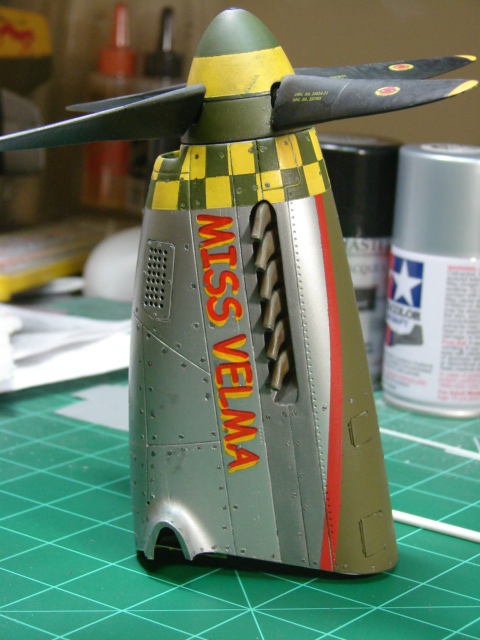
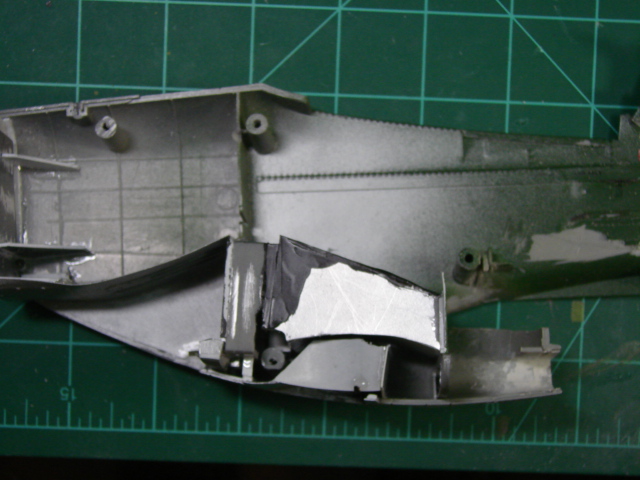
This picture shows where a large portion of the sides of the forward fuselage were cut away and replaced with white plastic stock with a correctly shaped and oriented (1.75 deg nose down) slot for the exhaust stacks. I decided to take a shot at unshrouded exhaust stacks which meant I had to produce a surface to mount them to. So I scratch built quite complex housings with thin plastic made to closely approximate the real thing, and what a challenge they were. They are shown in black above. Also, much putty and filing work was done on the carb air intake smiley face below the spinner, and new carb air filter perforated panels were fabricated, and their two openings created. Support structure for the prop is in there too (I wanted to make sure this prop can spin true, and it does).
This all worked to my satisfaction, so I could move ahead. The above picture shows the result of a new exhaust stack slot, several new panel lines, and a reshaped smiley face. Although not shown in the shot, I would later remove the lower forward center section from the wing and transfer it onto the nose, to facilitate sanding, puttying and smoothing of those lower cowl panels, and also to facilitate the assembly sequencing later in the wheel well. I don’t know how smart this was, but something tells me I had to do it. Please note the total replacement of the Dzus fastener depressions – very tedious but necessary.
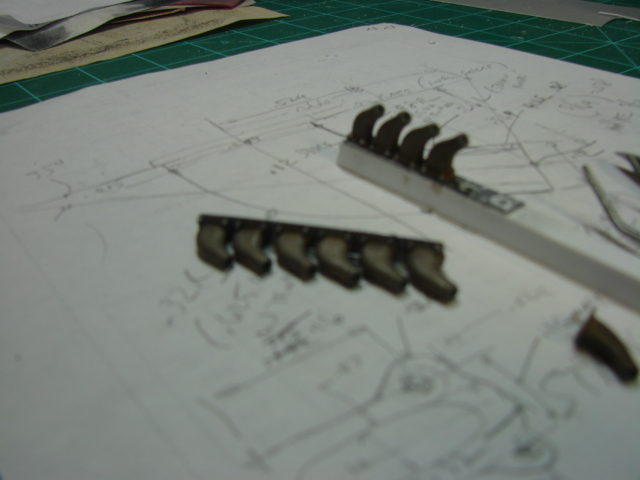
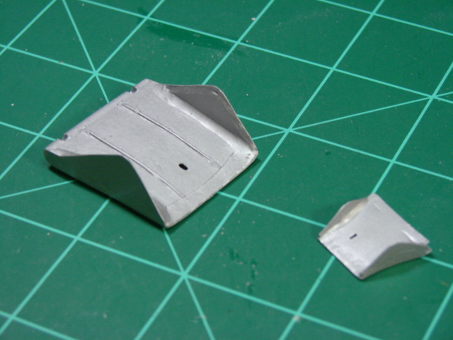
Here you see a somewhat fuzzy picture of exhaust stack work. I sawed and Dremeled these parts out of .125 inch thick plastic stock, using scribe lines derived from excellent NAA drawings. Then the corners were rounded off. Doing a couple of them was fun, but twelve? It was very hard work and took a long time. Surprisingly to my relief they came out really convincing looking with no great amount of skill required. They have mounting flanges with 4 little studs and nuts each.
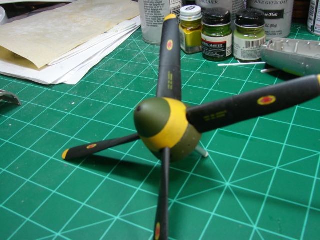
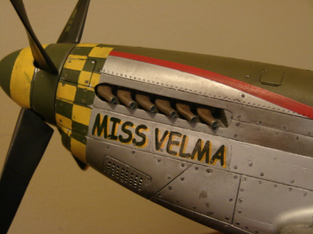
Here you see the completed Hamilton Standard cuffed propeller and spinner. What you don’t see is what’s inside it. Again – apologies for not having any pictures of that. The 21CT prop blades are almost correctly shaped but not quite, which is an improvement over all existing P-51 kits except the new Tamiya. The cuffs at the base are too tapered giving too wide a chord at their roots, and like almost all P-51 model props, the root diameter below the cuff at the spinner boundary is much too small and spindly. So I elected to pop open the spinner (it’s two-piece) and separate the one-piece prop into four blades and get to work reshaping them. The black (vinyl impregnated?) plastic used for the blades is almost indestructible. It sneers in the face of files and sand paper. But patience and determination will eventually get them to go in the direction you want. What you see is still not quite right but it was as far as I was willing to go. I removed the spindly attach stalks and made large diameter replacements out of aluminum tube locally flattened slightly to simulate the airfoil shape they have where they enter the spinner. I have a friend on the SIG who somehow cast some wonderful blades for his (long overdue) 1/18 effort – I hate him.☺ Inside the spinner I cooked up a complicated fitting to re-mate the 4 blades to each other and accept the new aluminum shaft on which it will spin, and used a fixture of sorts to set the blades squarely. The spinner itself was retained even though its dimensions are off a tad (it’s actually too short a few hundredths of an inch). I just reshaped the prop blade holes into the familiar hourglass shape seen on the real thing. Since I wanted the spinner painted before installing the blades, it was now that I had to commit to which individual aircraft I was going to model. And so I chose Miss Velma (55th FG, 343rd FS, serial number 44-14561, pilot Capt Frank Birtchiel) for three reasons – one it had unshrouded exhaust stacks which I had already tried and succeeded in building, two it had fairly easily reproduced nose art (although a tough prancing horse on the tail), and three it had IMHO one of the coolest paint jobs in the ETO. Back to the prop, one day I will make some good Hamilton Standard decals for the blades; until then the “airscrew” brand will remain. That’s comical...where did they get that?
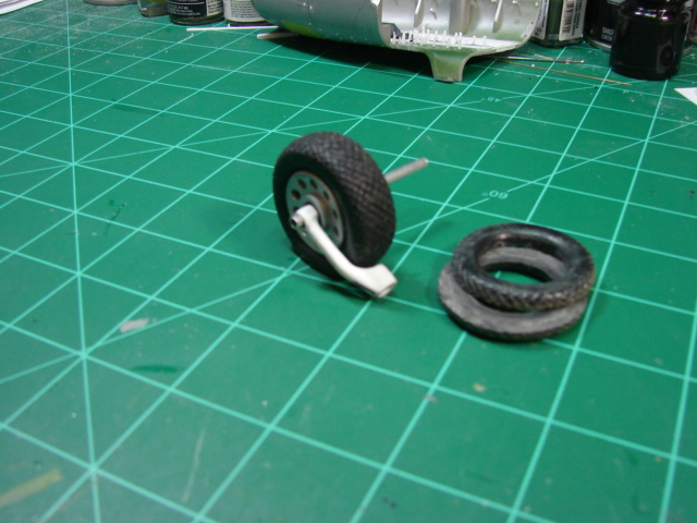
One huge deficiency with the 21CT toy is the landing gear. They had to be totally redone – super skinny tires, super fat LG oleos at the wrong angle, etc, etc. Landing gear is usually my favorite project, so I took this as a “challenge accepted”. However I just don’t have the skills to scratch build a new wider tire (some do BTW). So I split the existing ones in two, added a bunch of plastic sheet between them to get them to accurate width, and re-scribed grooves for the diamond tread. Again I had to deal with the evil black plastic but it reluctantly gave way to the surgical saw.
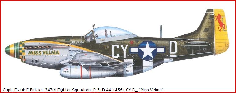
As can be seen above, the tread is a little too fine; I have to live with it. Also, importantly, I cut a flat in the tires to weight them, and added some putty around the flat for a bulge. Later after receiving some constructive criticism from the SIG, I lessened the flat and bulge some compared to what you see here and below. You will also see the lower leg of the LG, which also was sawed and Dremeled out of thick plastic material, except the lugs which made separate and attached. I would say getting this part correct (and its opposite to look the same) was one of the major challenges in this build. It is almost universally misshapen in all kits and all aftermarket parts regardless of the scale.
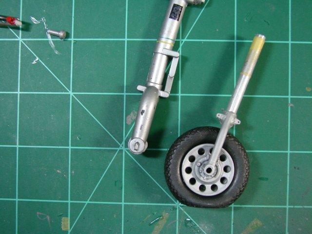
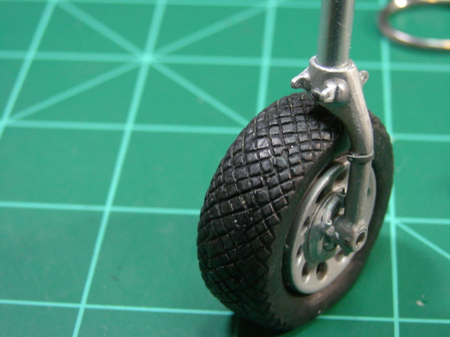
And nowhere is this more evident than with the 21CT strut as seen above. Beefy. Despite the silly looking struts, the wheels were salvaged from the kit, although I did a lot of filing and shaping of holes and slots, and created a representation of the inside of the wheel since you can actually see in there through the spokes.
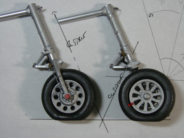
The upper oleos were made from aluminum tube stock as were the shiny inner cylinders on the lowers. Look at the support tubes extending from the tops of the oleos – they are actually that way on the real aircraft although at a different angle. The torque links were made from plastic stock and were also one of the rebuild’s major challenges. The real live parts are castings or forgings with a lot of small details that are worth modeling if one can do it (like lube fittings). Also note the scratch built brake lines, brake drums, and red tie-down fittings.
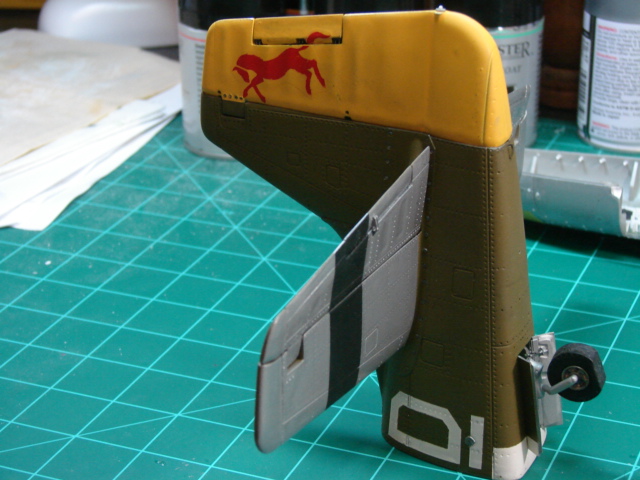
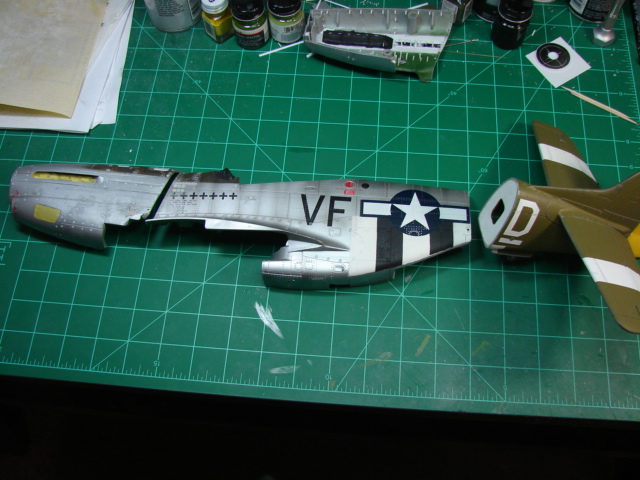
What you see here is the complete aft fuselage and tail. I did this very early on in the re-build because if I couldn’t correct the serious problems on the 21CT toy, I was not going to proceed. Boy do I wish I could show you what is inside this assembly, and show you the blow-by-blow of the fin, rudder, horizontal tail and elevators. But I failed to document it. Anyway – the fin and rudder split is mislocated and had to be shifted. I added some material to the aft trim of the fin, and re-profiled the slot for the rudder balance weight. The rudder was salvaged, but its leading edge was filed and puttied round. Also a fully scratch built rudder tab and control rod was made. The red prancing horse decal is homemade – I scaled it from a photo of the tail of a currently flying P-51. The tips of the fin and rudder were cut off and replaced by new accurately shaped parts cut out of (you guessed it) thick plastic stock. It really was heavy lifting. The horizontal tail was a bit better, but still required much filing and sanding to round out the leading edges. Again the balance weights and their cutouts were re-profiled, and the tips were replaced (in this case widened to address a short span), and elevator tabs and controls rods were added. Lastly as was done with the forward fuselage, I puttied over the Dzus fastener imprints in the fillet fairings and drilled and filled with new ones.
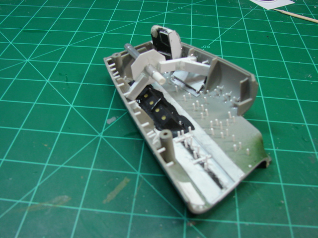
The fuselage cutout for the tail gear on the 21CT model was overly large and grossly inaccurate. So I covered it over with plastic sheet, re-cut a correctly shaped cutout, and made some new doors. I decided I was going to make an accurate tail gear assembly which meant I needed to attach it the way the real assembly is attached, which in turn meant I had to create inside frames and beams and webs similar to what is actually there. Now what I did not model was the LG bay canvas cover that these aircraft had in the field. This cover is usually not present in today’s flying Mustangs, but in war time they had to be there. I really didn’t know how to model that.
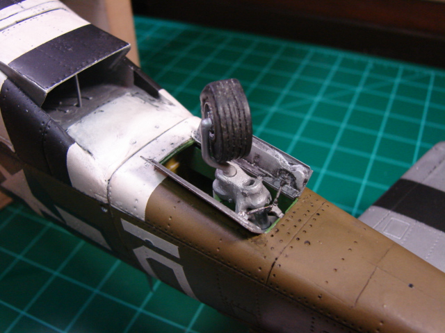
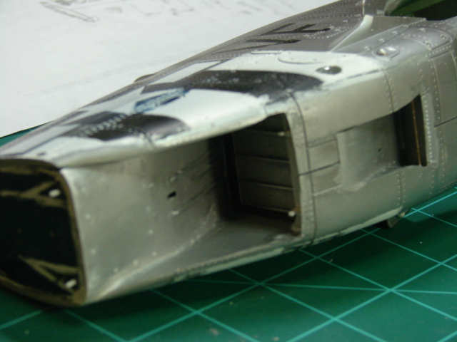
This picture of the tail wheel bay is as good as I can give you, and it is an opportunity to discuss the tail landing gear. The tail gear tire is actually the 21CT part with the middle sawed out of it to get its width right. Whereas the MLG tires were much too narrow, the tail gear tire was much too wide!! The wheel itself was not salvaged; I made its replacement out of tubing of various diameters. The lower strut is a bent up piece of copper tubing, and the LG fittings (lower and upper) were cut out of thick plastic stock. For some reason on the aft fuselage and tail gear, I had as much fun with this portion of the re-build as any other portion, probably because it turned out to be very accurate compared to the gross inaccuracies before modification, which was very gratifying. It allowed me to continue on with some confidence I could build a winner.
Somewhere around this time I finished up the forward fuselage including paint. You will now see the lower wing portion added to the belly which allowed the lower cowling panels to be smoothed and panel lines restored. At this time I felt I had to make some decisions on colors. Miss Velma is invariably shown by artists with a lighter green for the checkers, and a similar light green nose art lettering. And the “racing” stripe that separates the OD paint from the natural metal is usually but not always shown yellow (it is also shown red).
I have found color photos though which show the nose checker color as a much darker British green, and most experts I think agree this was the case. As for the yellow stripe – I studied all the black and white photos I could find of Miss Velma, and I have concluded beyond doubt (my doubt anyway) the stripe was red. There are color photos of some 55th group Mustangs which clearly show this stripe as red as well as the prancing horse on the tail, and I am sure Miss Velma was the same. The confusion stems from the washed out nature of many of the old period BW photos of Miss Velma. Now the color of the nose art lettering – you see I first chose red. But later I changed my mind and made it dark green. That is a guess on my part. I just know it wasn’t light green as the drawing shows. It is a homemade decal by the way.
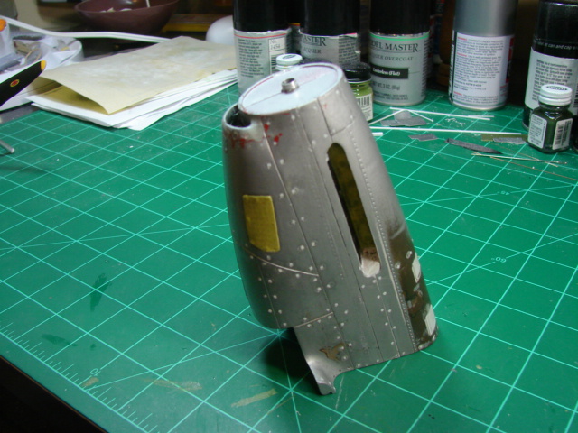
With the tail, and aft and forward fuselage sections completed it was on to the middle fuselage which would be as much work as the two other sections combined. First I had to address the misshapen radiator outlet area.
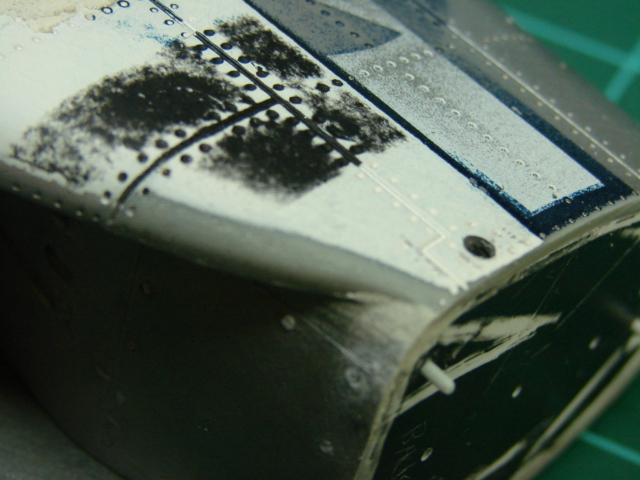
I don’t know if I can remember just what this part of the model looked like prior to modification, but not at all like what you see above. The soft underbelly which extends into the outlet is scratch built, and the curved sides of the outlet where they meet the fuselage proper was extensively reshaped and puttied to get it more accurate. I added a Sta 248 bulkhead with shear pins as can be seen above to firmly attach the aft fuselage when the time comes.
The outlet for the oil cooler was basically non-existent on the toy, so it had to be created from scratch from plastic sheet. This work along with some modified panel lines kind of got the lower mid fuselage in shape.
The radiator outlet door was made using the existing unit from the kit and then sidewalls and an inner panel added. Its contour isn’t really right, but neither is the bottom of the fuselage and they have to match. The oil radiator outlet door was entirely scratch built.
One of the really great things about the P-51 was its radiator placement under the fuselage – it contributed to its high top speed by keeping the draggy radiator inlet off the wing (Spitfire and Bf 109) or the forward fuselage (P-40 and P-38), giving a bit of aerodynamic area ruling maybe before it was even known about. Above is my attempt to provide the inner ducting. It is visible enough that something needs to be there. The Tamiya 1/32 kit appears to be the first P-51 kit where some attempt was made to represent this feature, and that influenced me.
That’s it for now. In the next part, I will show the development of the cockpit and fuselage tank areas plus more. Stay tuned.
Part 1 | Part 2 | Part 3 | Part 4
© 2012 James Wheaton
This article was published on Tuesday, July 31 2012; Last modified on Saturday, May 14 2016