
P-51D Miss Velma in 1/18 Scale - Part 2
By Jay Wheaton
Welcome back to the 1/18 Miss Velma build, or re-build. Part 1 took us through the fwd and aft fuselage, the landing gear, and the radiator area of the mid fuselage. Next we will focus on the cockpit area and just behind it where the fuselage tank and radio rack reside.
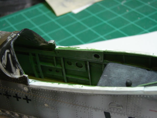
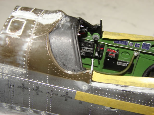
While checking dimensions on the model, I noticed some issues with the cockpit area. One, the canopy deck is too low, and two, the canopy area is a little too short in fore/aft length yet a little too wide. None of this was great news for an area that was going to packed full of gadgetry, except the extra width which would prove helpful.
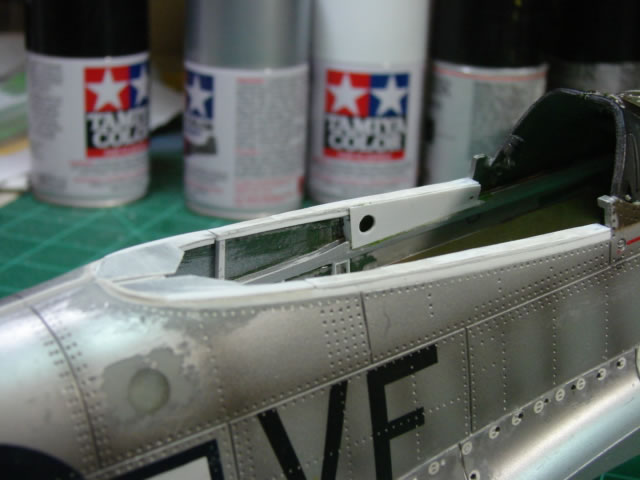
So I decided I needed to do something with the canopy deck. The length issue would be accommodated with some overly short parts here and there; it would pose some problems later as the plan was not very well executed. What you see here is the canopy deck frame on top of some build-up. Total material added is about 0.08 or .09 inch but it tapers some at the back. Depending on what you measure from, the deck probably could have come up some more. But anything I added to the canopy deck I had to grind from the canopy itself, and it had only so much to give from its base frame, so I limited it to that amount and called it a compromise. You also see the beginnings of visible framing on the inside of the fuselage, including the LH upper longeron, all made from simple plastic stock. And also visible is a very large epoxy-filled hole just under the aft end of the deck – there are several of these large holes in the toy’s fuselage, used to access screws that hold the fuselage halves together, and all had to be filled and smoothed. This one was easy, others were harder due to local contour.
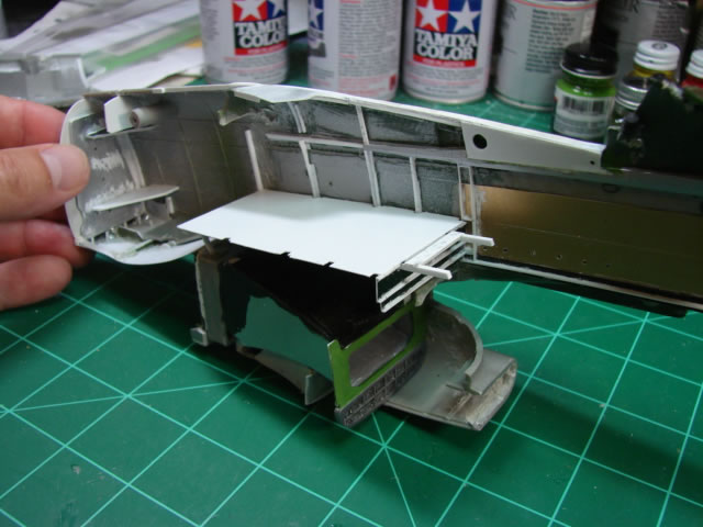
This model was going to have a deadly accurate fuselage tank by golly, so off to work I went constructing an accurate floor on which to mount it. The floor is actually called the radio compartment floor, designed to accept radio racks prior to the time the fuselage tank was added. The B and D model Mustangs could be described as heavily armed flying fuel tanks, done so in order to escort the heavies all the way to Berlin and other far away German targets, from England or Italy – thus the fuselage tank and the familiar drop tanks on the wings. Above you see some aft framing and the floor – it’s neat but I thought at least some of it could be seen on the finished model, and you really can’t see it. Oh well, the floor or something like it has to be there for the tank, seen or unseen. You get another view of the radiator doghouse and the Sta 248 bulkhead and its bracing elements as a bonus. The two bars poking out in front of the floor are for mounting the pilot’s armor plate. In order to install all this framing and the framing further forward in the cockpit, I had to scrape/tear/Dremel/pry off nearly all the sparse mock framing and other stuff protuberances on the insides of the toy, including most of the heavy posts used for screwing the fuselage halves together. This was hard and dangerous work – the toy is not designed to be disassembled and is extremely stout.
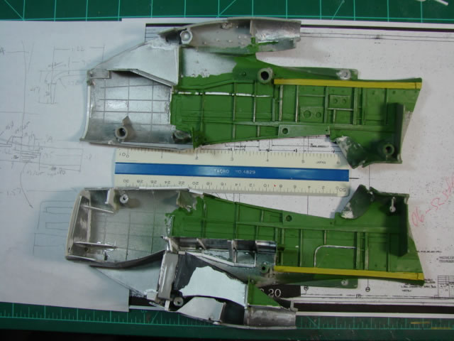
Here you see the mid fuselage framing at or near completion. I should mention that it is an integration nightmare to try and anticipate the fit of all the parts that will go into the cockpit and radio compartments, due to the scale errors on the model, and the thick gauge of the plastic. This also holds for the radiator ducting you see (the doghouse). So I 3D modeled everything on the computer, along with some digital approximation of the existing fuselage inner surface, where it made sense to. This really worked well. I designed scratch built parts as closely as I could to the engineering drawings and altered as required to fit with what I was stuck with. By the way, I salvaged none of the 21CT cockpit parts except the instrument panel and only used it to punch out the instrument dials. Note the upper and lower longerons are in there as well as the vertically oriented frames. These parts need to be there to mount various other parts (like the cockpit floor and instrument panel). The longerons have reduced section height to try to make up for the thick plastic gauge.
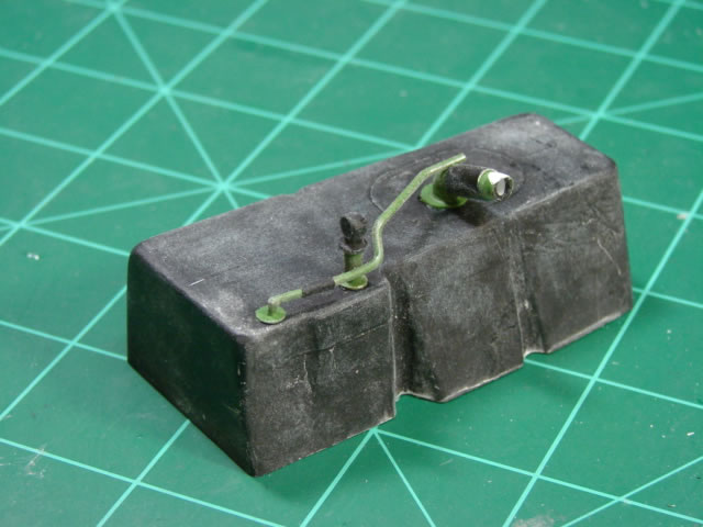
And here is the fuselage fuel tank which is a quite accurate representation of the real rubber unit, with a fuel quantity gauge and filler tube and some more lines. This part was made from many pieces of thick plastic (.25 x .75, and .25 x .25) glued together. Look hard enough and you can see some of the seams. It’s big, and it’s heavy. It too was dangerous to fabricate because of the heavy sawing, filing and Dremeling that was required to get its final shape. The grooves on the sides are there to clear fuselage frames, just like the real thing. I wish it could be seen more easily on the finished product but if you know where to look for it, it’s there.
Above is just a shot showing finished fuselage framing and a dry fitted fuel tank. The actual aircraft had balsa wood spacers between frames and the fuel tank to help it retain its shape and distribute load. I decided to spare myself the aggravation of fabbing up these parts mostly because you really can’t see them well once everything is in place. The mid fuselage framing was pleasing work and it went quickly. Note the instrument panel shroud from the toy is still there – not for long…
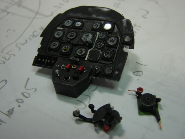
After framing was complete it was time to adorn the cockpit with equipment. I did lots of research to make sure this P-51D-10NA ETO aircraft had the right stuff in it. There was much to learn, and the engineering drawings show very many configurations of different versions of components such as the instrument panel (IP) itself, which seemed to change with the wind. This assembly seen above is made from thin plastic sheet, with instrument housings made from aluminum tubing (three diameters total for three sizes of instrument dials), and the instrument dials from the original IP. I used a Waldron punch to get the faces free from the original part, but it was necessary to sand it down to a thickness thin enough to punch. My punch set just happened to have the right size punches to do the job. Then the faces were covered with thin clear plastic (also punched), and surrounded by a scratch built bezel of good scale thickness (I think made from 0.015 inch sheet stock). Also you will see a lot of other stuff around the IP on its support frame including switches, switch covers, buttons, and other dials. Some of these, like the O2 gage, required a homemade decal. And lastly lying next to the IP you see the scratch built O2 regulator (easy), and the scratch built pre-K14 throttle quadrant (not easy), ready for installation on the sides of the cockpit walls. The assemblies you see in this picture are good examples of the “skyrocketing part count” that happens when fine detailing a large scale model. You will see a lot more.
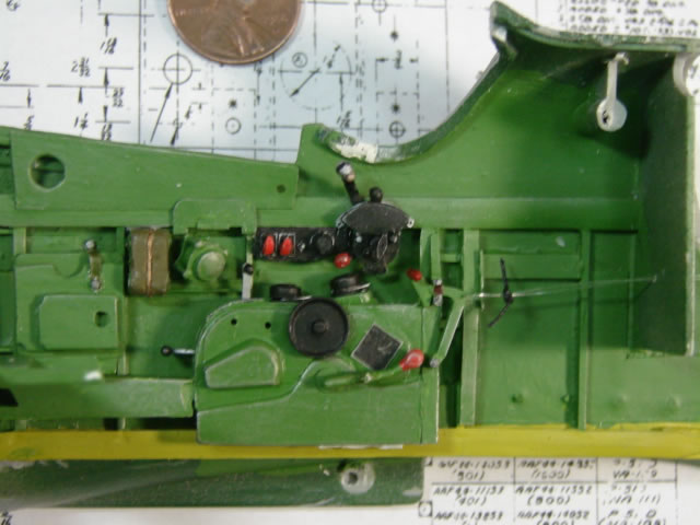
Here is the LH cockpit sidewall finished or nearly so with throttle quadrant, control pedestal, an electrical panel, flare gun port, flare gun bag, and map case, all scratch built from simple plastic stock and all lots of fun. Note that now the original IP shroud has been cut way. It just wasn’t the right shape. This move was a leap of faith, as the replacement shroud was to be scratch built by bending up a very carefully shaped piece of plastic sheet, and its geometry would be very tricky indeed.
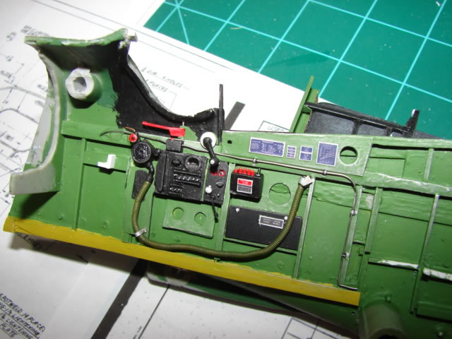
And here is the RH cockpit sidewall pretty well finished and sans shroud, with cockpit emergency release handle, oxygen regulator and hose, switch panel with ammeter, canopy crank, VHF radio control panels, and a cover panel which I have forgotten what it’s for. This side is not as crowded as later variants that had tail warning radar and other stuff to crowd it. So more framing is visible. A word on the O2 hose – it is made from .032 inch solder, with .015 inch solder wrapped around it about a million times. This worked really well and its final diameter is just about spot on for 1/18 scale. It can be deformed into the shape you want. Notice also the homemade placards on the trapezoidal shaped sidewall panel. They have all manner of info on them which I dutifully reproduced to scale, only to see it all go too small and fuzzy to read, but it looks convincing enough I think.
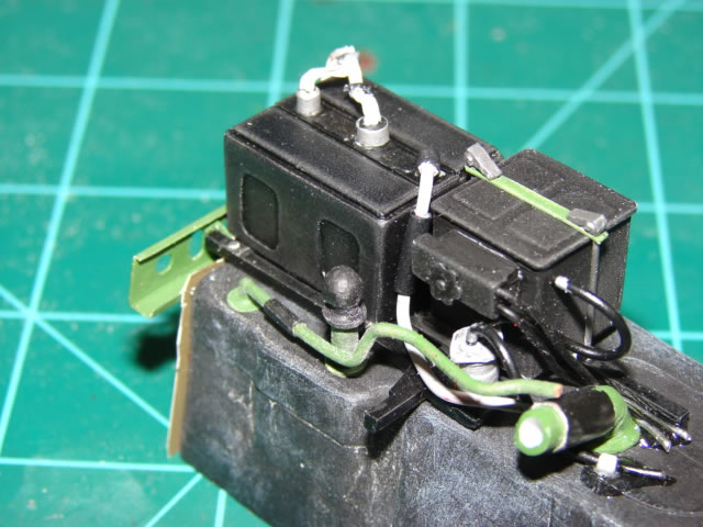 (pic 25 - tank, radio, battery)
It was time to tackle the stuff on top of the fuselage fuel tank. A radio rack was made from .06x.06 square plastic rod, and it was mounted onto the tank with some thin spacers. A horizontal frame was fabricated and attached to the front end of the radio rack (or maybe vice versa). It is the chromate green member in front it the radio. This frame is there to support the pilot’s seat and armor. It is made from 0.005 thick plastic sheet bent up with flanges as shown. I love that part – it turned out great, just like the drawing. It will later attach to fuselage frames at either end. The radio and battery were both scratch built from sheet stock. I consulted the web for dimensions and good pictures. At this scale one can model up lots of detail, so I have a pretty good representation of the wiring harnesses and cables and other plumbing. Note the bottle just adjacent to the battery (for battery fluid overflow). The battery clamping hardware was micro-surgery and a bit of a challenge. All in all this was immensely enjoyable to do. There was very little guesswork involved – just research the size and appearance, and build it. Flat sides and 90 deg angles mostly…
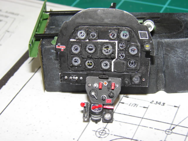
Meanwhile the IP details were finished up. Added were the fuel selector panel, another instrument, and the fuel shutoff lever. Some challenging decaling here added to the fun. This is now ready for installation. A word to all you who think the white stripes on the face of the panel should be yellow. That is incorrect – it was later in the development of the P-51D when it was turned to yellow, for reasons I cannot say. And that isn’t all that changed. What you see here is an IP configuration mid way through its evolution, and good for the -10NA variant.
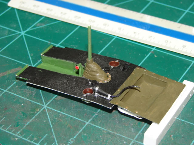
It was time for the floor, and the 21CT part was not going to do. This required much research, not so much to pick out a variable configuration, but just to sort out all the defining drawings for a floor that was much the same for all the D-models. There is a lot to this assembly. The aft portion is a representation of a canvas debris catcher of sorts which is under the seat and attached with brass snaps. It is made of formed .005 plastic. I worked it pretty hard for a part that isn’t seen. The next floor panel forward is made of .015 plastic sheet with some rod stiffeners underneath; the actual part was made of wood. It has the pee tube and bracket, heater controls, and big cutouts for fuel level gauges for the wing tanks. The gauges are in there too with homemade decals, housed in cans made of aluminum tube. It also has some of the snaps for the control column boot. The forward panels of course are split, were also made of wood, and have vertical thin plastic walls that come down to a sub floor which in reality would be the top of the wing. The control column tapering shape was done with patient sanding of a simple plastic rod, and the boot was shaped out of a block of plastic. Later the handle was fitted to the column, which was also hewn out of a piece of plastic block. The fitting in front of the boot is for a control lock linkage. It can be seen so I had to put it in there, and it was a little piece of micro-surgery. The floor was a very pleasing build mostly because it wasn’t all that hard to do, and it looks pretty real. It is now destined to be mounted on several little brackets attached to the lower longerons.
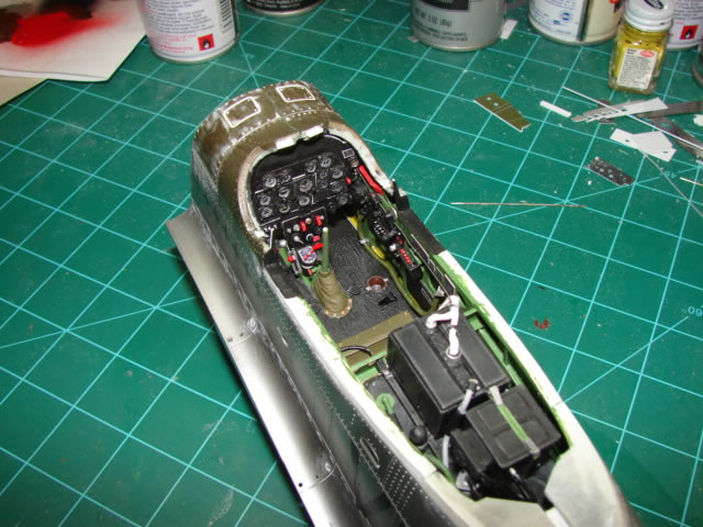
It was about this time that the two mid fuselage halves could be glued together – a large milestone considering the hundreds of parts that go into it and the months and months it took to do it all. The join was an involved process of making sure the IP, the radio floor, and the fuselage tank with radio and battery were aligned properly, and getting it all together before the glue and epoxy dried. Most of you can relate I am sure. At this time I was glad I had split the fuselage in three. The floor was actually installed after the mid fuselage was glued together – it was slid in from the front. When I first dry fitted the floor the shortness of the cockpit bit me and generated a clash between the control lock fitting in front of the control stick and the fuel selector panel that hangs down from the IP. This was a bit of a shock, as everything in the cockpit had been going so well. So I whittled away at this and that and crowded the control lock fitting into the control column, and also pushed the IP forward a few hundredths of an inch, and solved it after a fashion. Why didn’t that show up in the computer modeling? Because I created two separate and independent models for the forward and aft cockpit, inexplicably. So above you can see the nearly complete cockpit. A discerning eye will notice the absence of the Detrola radio and its bracket on the floor. ETO aircraft did not use this radio and it along with its equipment (including the long aerial antenna extending from the pilot armor back to the fin) was removed. It’s really easy to see all the cockpit detail without the seat and canopy and windshield. Those are to come very soon.
But first the IP shroud had to be dealt with. The integral shroud on the toy jutted up too far, and had the later version bead-stiffened sides that -10As didn’t have. It was risky to cut it off and go with an untested scratch built part, so I was nervous about it. The part you see above is made from formed thin plastic stock (.02 inch I think) carefully trimmed and shaped and formed to fit in the curved profiles of the windshield cutout. I actually think I got it to work first time, but I was prepared to do it over several times before getting it right. The computer modeling saved the day here. The ribbing around the aft edge is just thin plastic rod. That ribbing is cut back at the centerline to accept the gun sight mount. I considered this a major victory, and a relief.
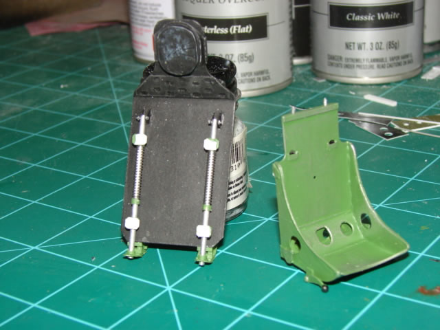
Of course the 21CT pilot’s seat and armor plate were replaced as well – I don’t have a picture of the original piece, but you would understand. The armor plate changed at least three times for the P-51D, each time it got taller. I guess too many pilots got their hair parted. ☺ The -10A aircraft got the middle vintage armor and that is what you see here. This project was fun – flat plastic parts and a chance to be deadly accurate. The only tough part was to fabricate a head pad that looked real. It’s OK but not great – at least it has some wrinkles in it and a bead. I probably should have painted it brown, but I have seen black ones too. The seat tubes are mounted on fairly authentic representations of the actual support brackets. The top ones have little bolts and nuts represented.
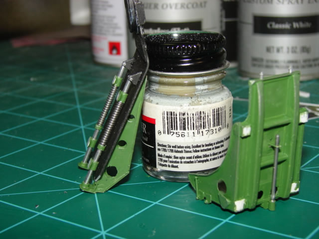
Let’s talk about the seat. P-51Ds came with one of two seats – a Warren-McArthur (WM) seat or a Schick-Johnson (SJ) seat. The WM seat is the more familiar one with the drop hammer shaped buckets for the seat and seat back, with rails around the sides. Sorry I didn’t provide a picture. What you see here is a SJ seat, which was made from flat sheet metal with less severe forming. My research indicates the SJ came in later in production (like the -20NAs), although the drawings and parts catalogue do not give a serial number or a time in which the change took place. And pictures of Miss Velma clearly show the WM seat. So why didn’t I make a WM seat? Because I didn’t know how to simulate the deep compound curves of the WM seat and seat back. A vac form and a mold would have done the trick – but I do not have a vac form. Anyway the SJ seat was quite easy to build and lots of fun to boot. I have accepted the inaccuracy. Those of you who have the new 1/32 Tamiya P-51 know that both seats are included.
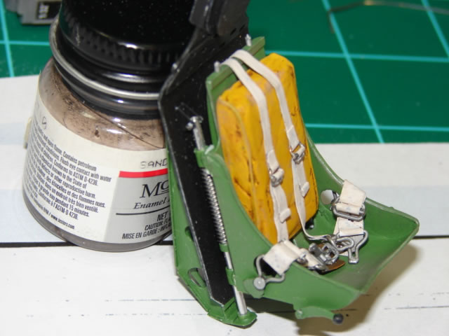
Here you see the finished product ready for installation. The seat cushion is made from (once again) a block of thick plastic. It is yellow because they actually were yellow to my surprise. Enjoy those nice looking wound solder seat springs while you can – they will disappear from view after the seat is installed. The seat belts were made from lead wine bottle wrapping – not the cheesy thin stuff but the thicker stuff. The buckles are bent up wire mostly. Again, 1/18 scale allows a good bit of detail.
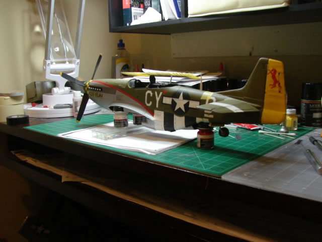
Before installing the seat and other stuff that would complicate masking at the canopy deck, I decided to paint the mid fuselage. This was the most challenging paint job I had ever attempted. It involved six colors that had to be sequenced and masked right. I won’t go through all the details, but the biggest reason it was a challenge was that I decided to paint the stars and bars and the squadron letters instead of making decals. You can see it takes up some desk space. Now it’s starting to look like a Mustang.
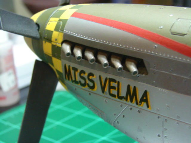
It was now also that I decided dark green over yellow was the proper color for the nose art lettering on the forward fuselage, instead of red over yellow. There it is - you can be the judge. While I was at it, I decreased the size of the decal; the red one was too large. Bonus – a great view of the unshrouded exhaust stacks.
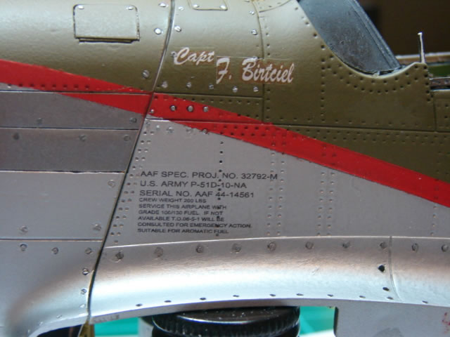
The lower decal shown above with the serial number was easy to make. The upper decal was not. I do not have a copier that can make plain white decals. Instead I have to use white decal paper and color the background. It took quite a lot of tries to generate a shade of OD that matched up adequately with the OD paint on the model. Also in this shot you can see I have replaced many more Dzus fastener imprints on the fillet fairings. In the next part I will show the important work on the windshield and canopy which lead to final completion of the cockpit area and the mid fuselage, and some of the wing work.
Part 1 | Part 2 | Part 3 | Part 4
© 2012 James Wheaton
This article was published on Tuesday, August 07 2012; Last modified on Saturday, May 14 2016