
Vintage Fighter Series 1/24 Curtis P-40 Tomahawk Part 3
By William Joyce
Next I painted all the interior green sections of the fuselage, dry brushed to highlight and weather. The fit here is good all around.
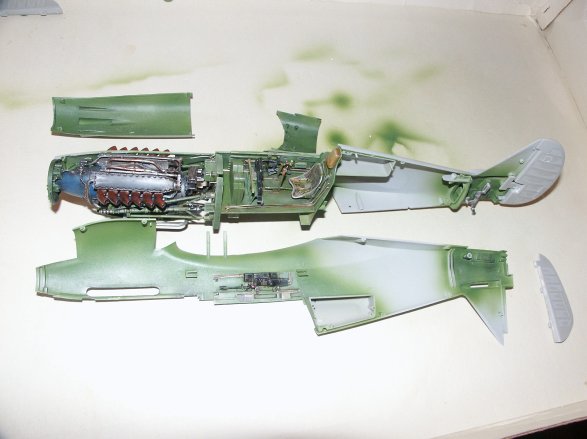
I like this stage of assembling a kit. I have been working on the interior parts for awhile, which is cool, adding detail and all that stuff. But now it’s beginning to look like an airplane. Below are some close ups of the cockpit walls. With the interior walls being cast separate from the fuselage, once glued in place, a gap is present. By-the-way I think this is a good thing, working on the cockpit side panels is much easier with them being a separate piece. I will fill, sand, and paint these areas before final assembly of the fuselage.
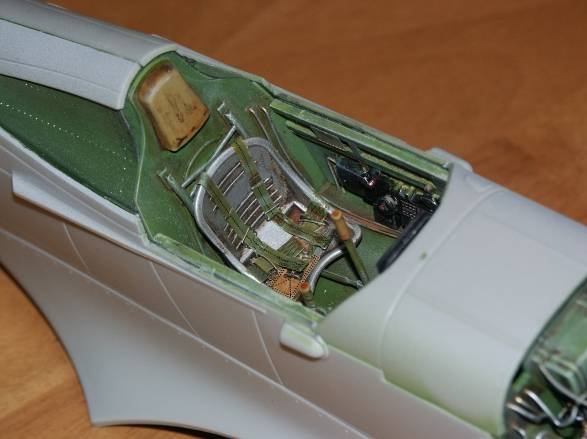
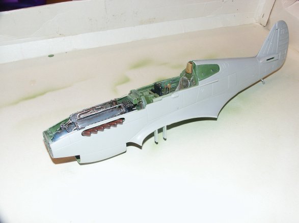
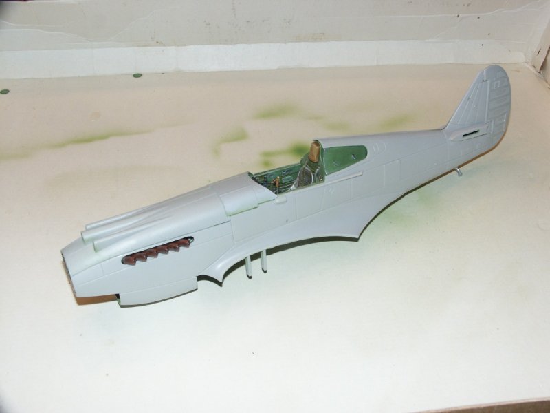
The fit with all top covers is very good. Looking like a P-40!!!
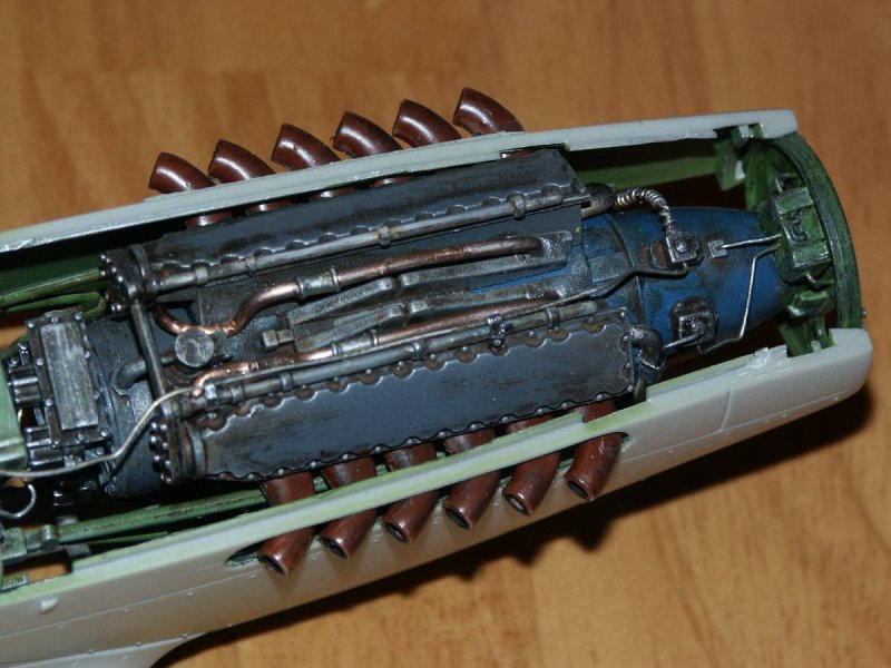
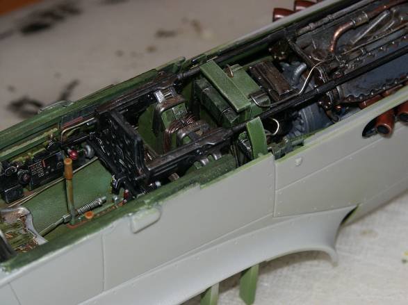
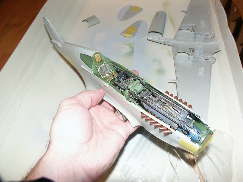
Below is a close-up of the engine compartment. The reviews were correct! Only the very top portion is visible once installed (without removing panels).
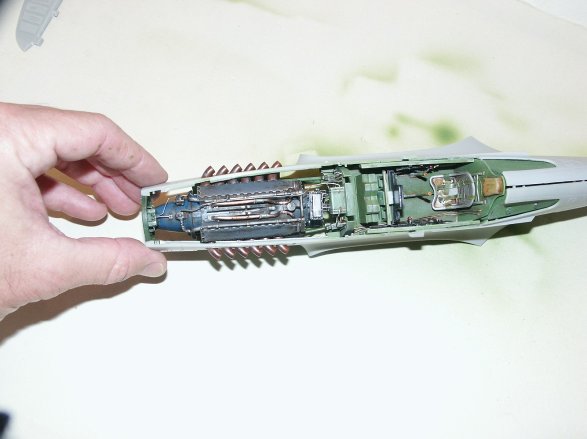
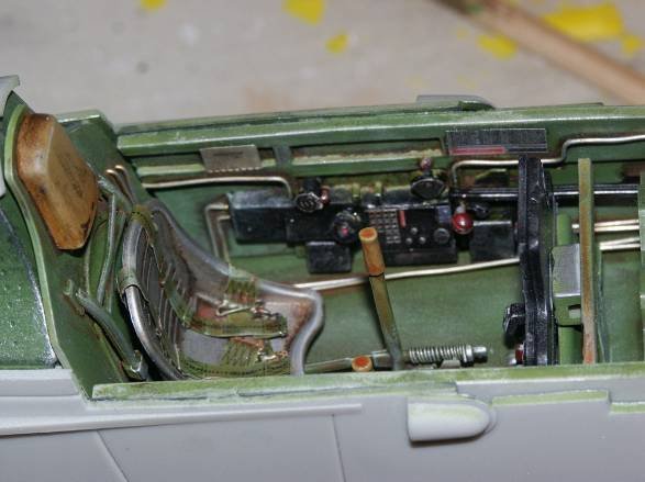
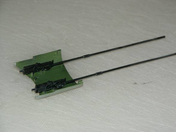
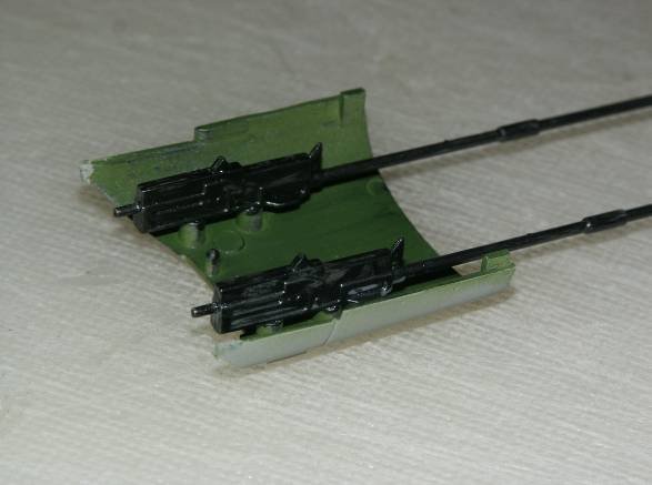
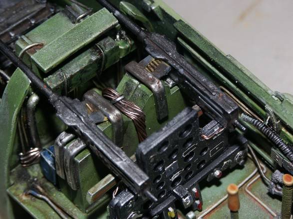
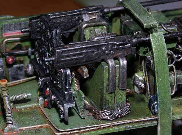
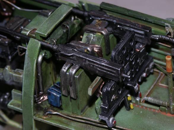
Ok back to the cockpit area. I reached the point when it was time to glue all the components together. The kit calls for the two center mounted machine guns to be glued to the inside top of the cover (pictured below).
To display the engine and firewall areas you need to remove both the engine cover and the gun compartment cover (cover section just in front of the cockpit). They kinda lock together. Well…..once I glued the guns in place and one last test fit and….with both covers removed the area just behind the firewall and in front of the instrument panel looked stripped!
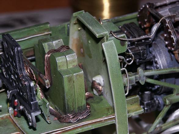
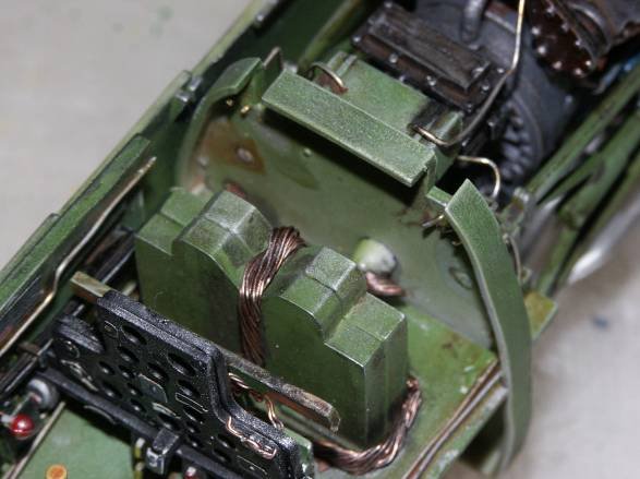
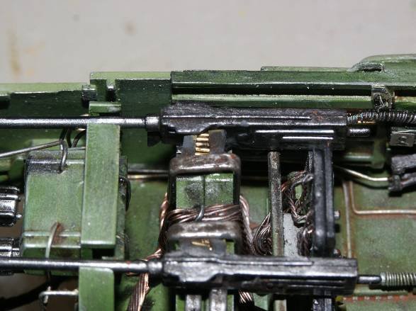
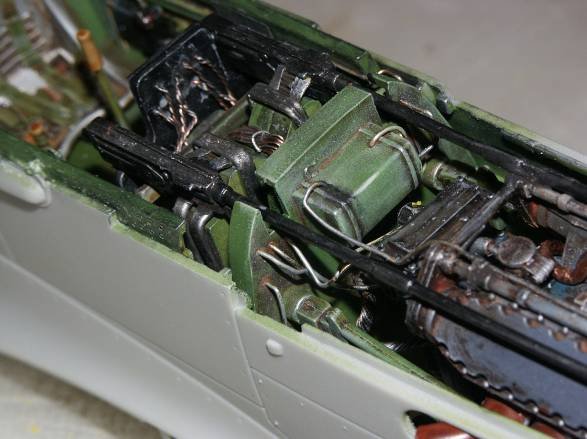
I was working late one Saturday night, had a few adult beverages (liquid courage) and the decision was made….more detail needed here. So I backtracked a bit and added some wire behind the instrument panel and some detail to the back of the firewall.
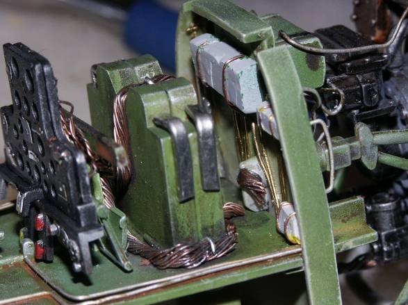
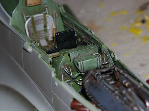
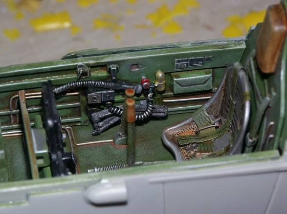
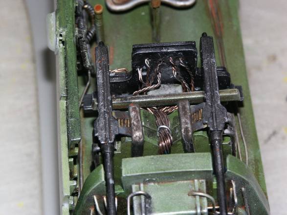
I used speaker wire along with crayons (cut to shape then primed) to simulate structure behind the firewall. I also decided that I was going to remove the machine guns from the top cover and fix them to the interior section for better display; I’m guessing that’s the magazine for the twin 50 cals? I must say, I’m flying by the seat of my pants here! Using artistic licensing, for all the wiring, firewall, and especially gun placement! OK…..confession time, I could have just deleted the immediate above section, due to a potential miscalculation and nobody would know the difference?
While looking over the instructions, and I realized the front section of the canopy fixes to the section that covers the above mentioned. OOPS!!!! Do to the nature of the connection, however, two pins under the cover, the entire section can be removed, cover and windshield, so no problem. Lesson here, think….think…. ahead to the final product?
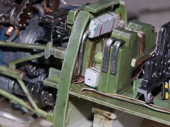
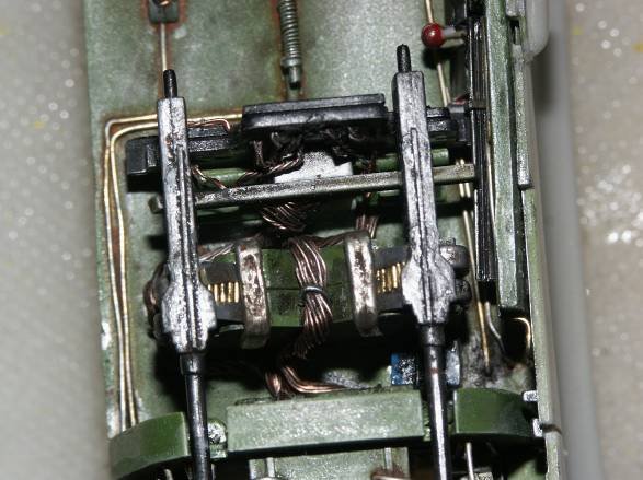
I used solder; beat with a hammer to flatten, for the gun mounts and belt feeders. The 50 cal machine gun belts were simulated by cutting 24-gauge wire (say 3/16 of an inch in length), placing on a masking tape backing, then additional masking tape on either end to simulate the end-cap belt feeders.
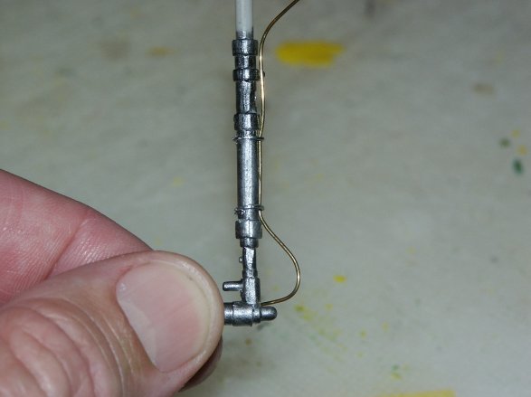
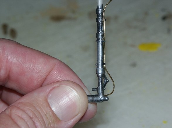
I then fabricated brake lines from the 24-gauge wire and clamped them to the struts. I used standard staples, straightened, and then crimped them to the strut.
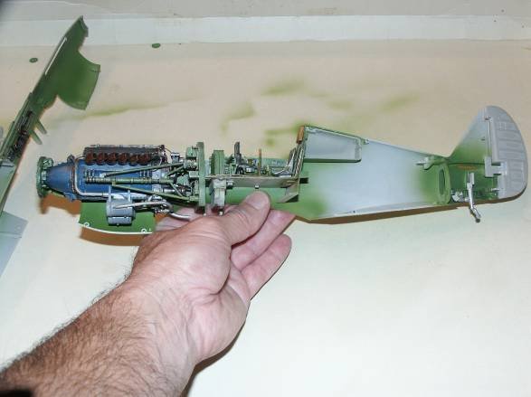
I finally cemented the fuselage together!! I will fill and sand the seams. Fit here is good all the way around. I always fill the fuselage and wing seams, even though the fit is really good…..have never come across a perfect seamless fit!!
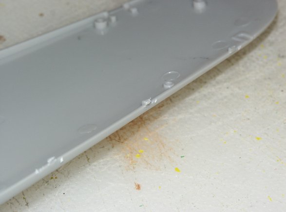
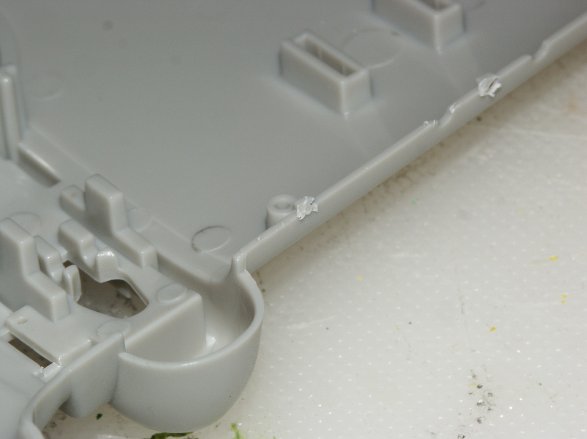
The wing sections were molded with the same “tabs” as the fuselage (previously mentioned). Once again not a big deal, they were easily removed with a blade.
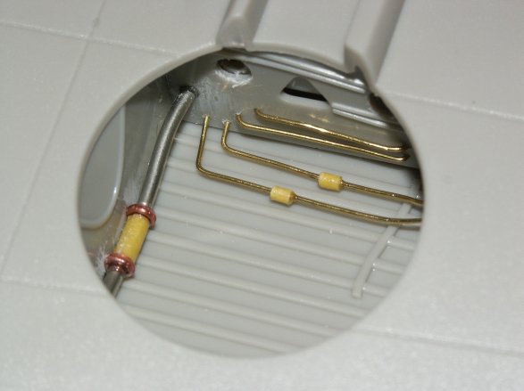
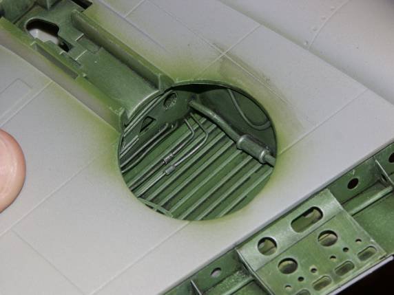
Wheel wells and flaps were next. I decided to add a bit of detail in the form of hydraulic lines. Started with the smaller 24-gauge wire then added a larger line represented by a piece of solder, masking tape, then edged with smaller wire (filter doohickey). With just masking tape I then added a smaller doohickey to each of the 24-gauge lines.
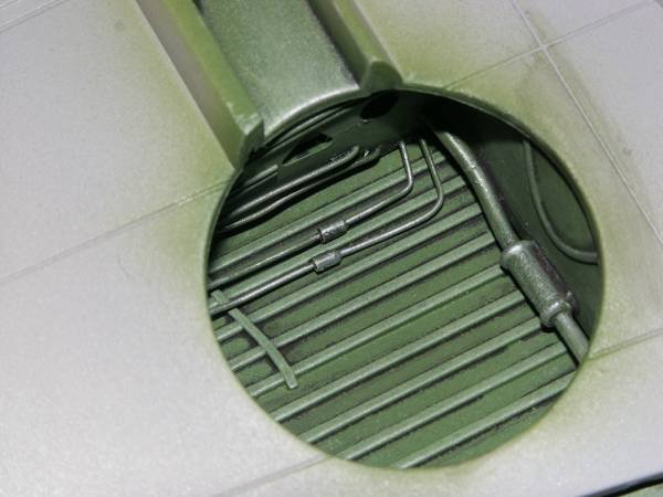
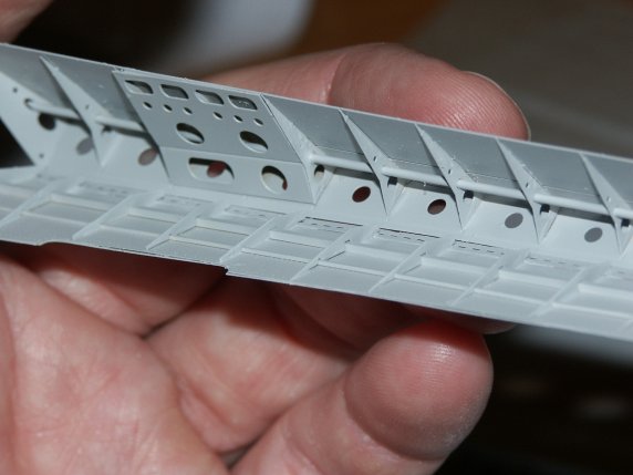
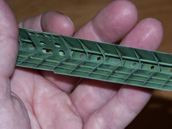
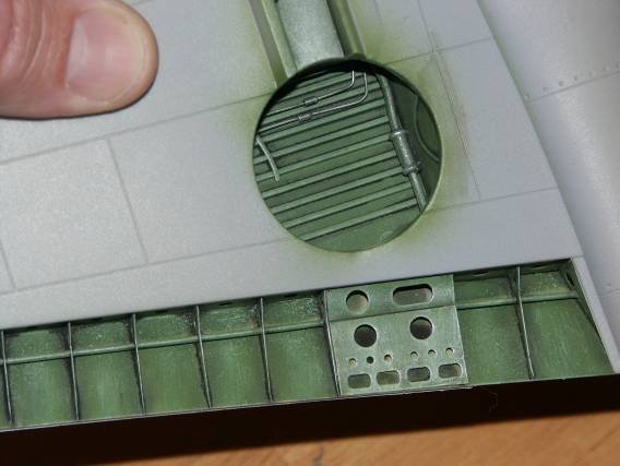
The wheel-wells were primed, painted, then weathered by applying an oil wash and dry brushing. You can see the Cammett upper flap section.
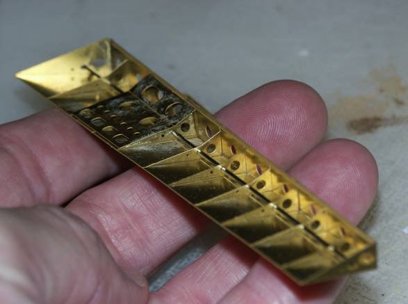
The Cammett flaps. These aftermarket beauties are amazing! I just don’t know how else to say it? The detail is stunning, down to the rivets, and construction was a breeze (first serious aftermarket product for me). The flaps were primed, painted, and weathered. Below are several pictures of the flaps, as you can see the fit is perfect. I hope the pictures do them justice?
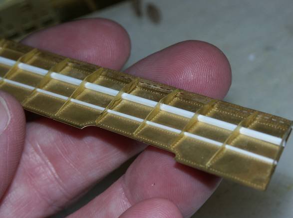
I highly recommend the set and as far as I’m concerned they are a must. As the reviews promised this area has been completely transformed!!
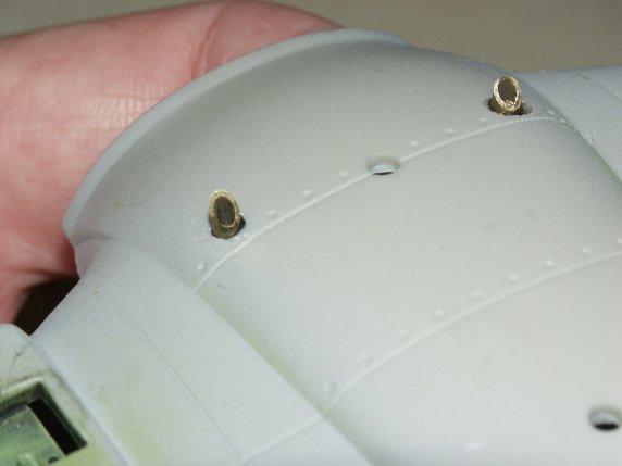
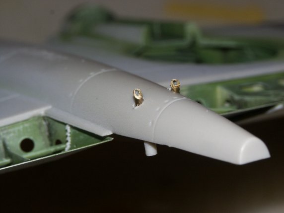
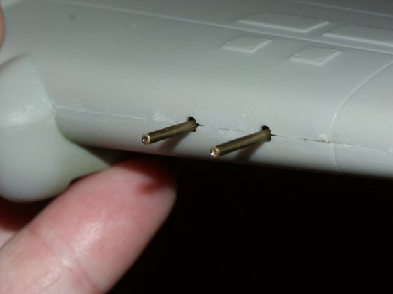
Next I added fuel drains to the front and aft sections of the fuselage. I placed the drains according to the decal placement directions. I used larger brass tubing for the front drains and smaller tubing for the aft drains. I just figured everything gets larger the closer you get to the engine?
The wing guns for the kit are hidden with no pre cut access panels to view them. They are also a bit bland. I just did not like the barrel representation. I used brass tubing here as well. I cut four sections and epoxied them into place. I fixed the brass tubing to the wing, matching the barrel length of the kit guns.
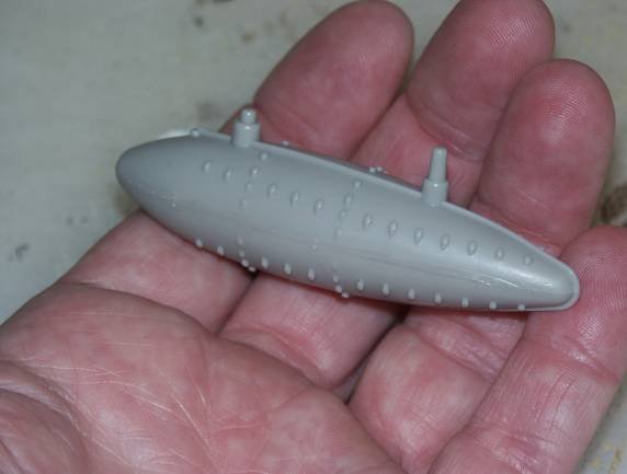
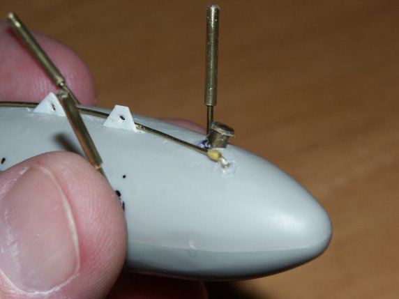
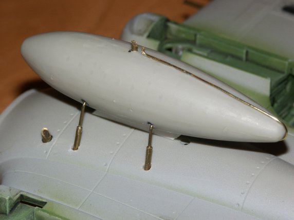
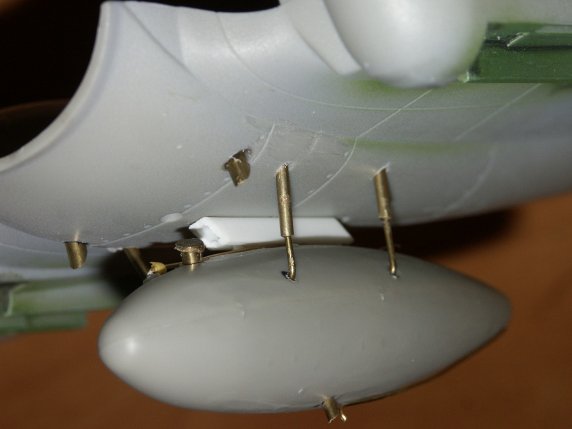
The external fuel tank was the next job. The tank is not a realistic representation as mentioned in several of the reviews. I filed off the exaggerated rivets, added a fuel fill port (brass tubing), tank overflow (24-gauge wire), fuel drain (brass tubing), and mounting hardware (brass tubing). Below are some before and after pictures.
Next the wing section will be fixed to the fuselage, and then prepped for painting. Getting closer!
© William Joyce 2008
This article was published on Wednesday, July 20 2011; Last modified on Saturday, May 14 2016