
Vintage Fighter Series 1/24 Curtis P-40 Tomahawk Part 2
By William Joyce
Back to the build... Next step called for assembly of the cockpit, engine, and firewall units. All parts fit very well here.
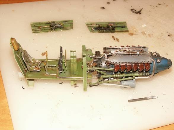
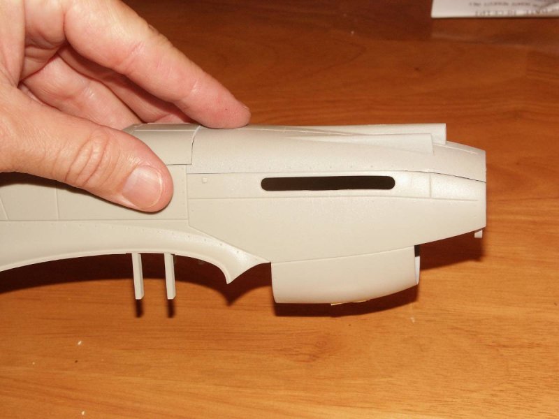
This unit was then test fitted to the fuselage, the two fuselage half’s fit very well except for exhaust ports.
I found that the engine cover would not sit down flush leaving a gap toward the front of the engine. After close inspection I determined the exhaust ports were forcing the top of the side panel upward. This was on both sides. You could clearly see no free space between the top of the exhaust pipes and the bottom of the side panel.
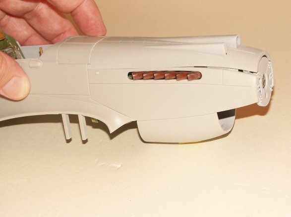
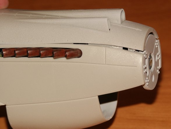
Now I must say here, I’m taking the heat on this one, chalk it up to “modeler error”. So what I did was test fit without the engine assembly.
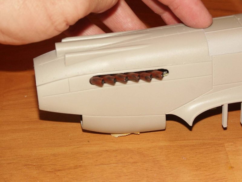
The fit was much better……the only thing I needed to do here was dremel off a small portion at the center (high center) of the to engine cover. I then used the dremel to increase the port opening by grinding off a small portion (say 1/16 of and inch or so) at the top of the opening. With that the fit was fine.
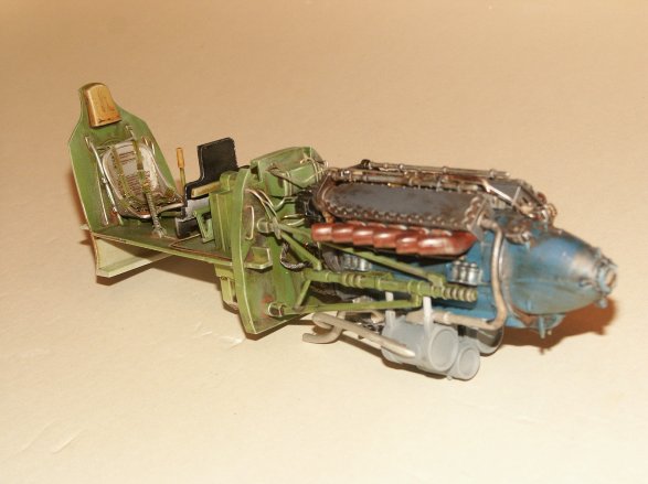
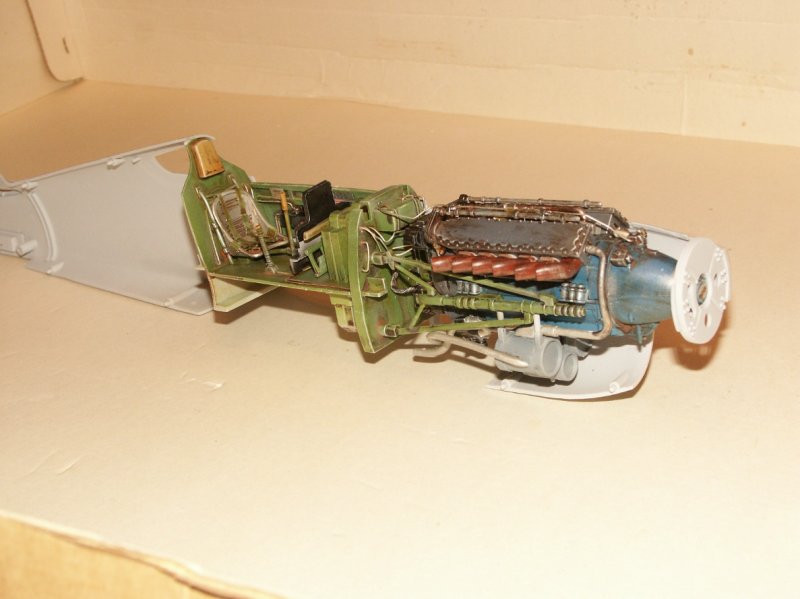
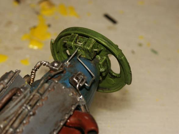
With the engine assembly inserted into the fuselage I could truly see what was going to be visible. Only the very top as mentioned in the kit reviews. Again I decided to add some extra detail right behind the prop. It just looked bare! So I decided to add a magic box. Again, adding eye candy. My approach to modeling is like art. I believe in creating visual realism, to scale, that catches the eye. So I use a bit of artistic license and took one of my son’s crayons, a yellow one, (easy color for these failing eyes) and x-actoed a small rectangular box. I then took aluminum foil, shaped some bands, wrapping on both ends.
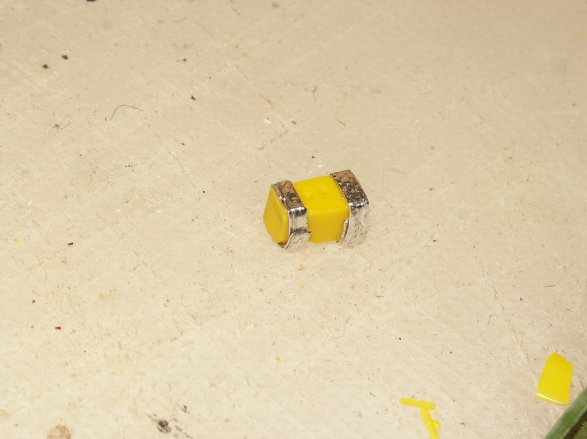
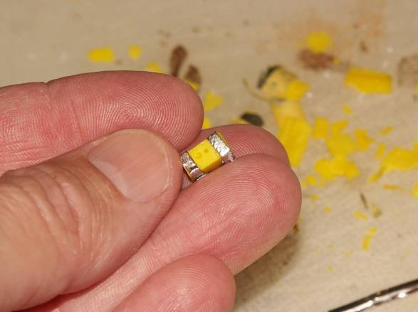
I then 5-minute epoxied the piece right behind the propeller, cut some 24-gauge wire to shape and ended up with some eye candy. I then primed, painted, Futured, applied an oil wash and there you have it.
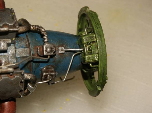
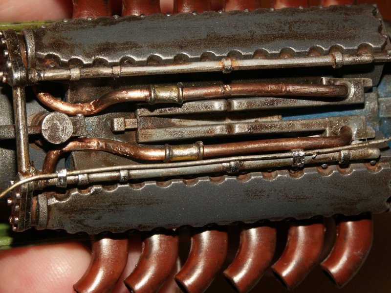
At this point I add clamps to the wiring on top of the motor. The clamps were again made from foil folded over several times then wrapped around the wire.
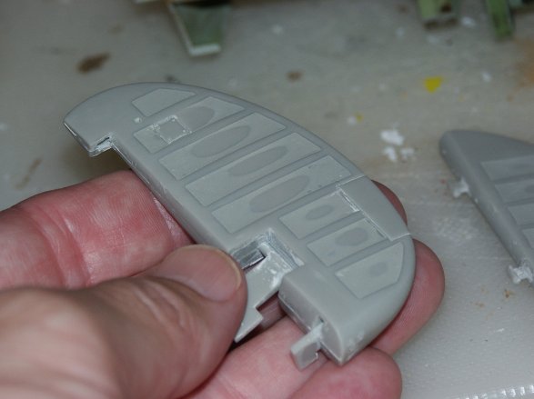
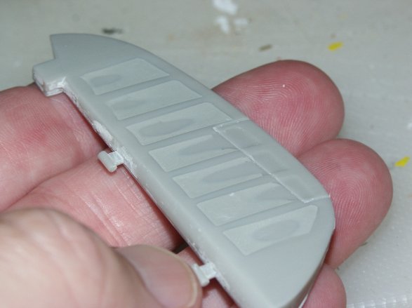
After reading several reviews, the flight control surfaces were not given a thumbs up. They were too pronounced. They just did not look like fabric covered sections. Now…..this could be a good thing once completed. With pre and post shading the surfaces just might be eye catching……that economy of scale thing? Sometimes you have to exaggerate to achieve the effect you are looking for. But, here I decided to soften the sharp lines in the rudder and both stabilizers.
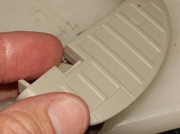
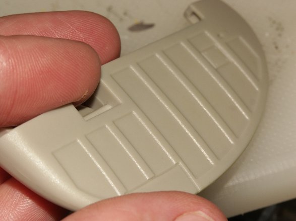
So I call upon Nitro Stan filler and filled in between ribs. I then sanded, filled again and sanded one more time.
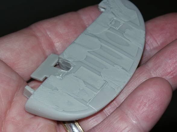
It took a couple of times filling and sanding to achieve a nice smooth transition from the center to the edge of the ribs. I ended up with some pitting that needed to be filled the second time which was due to not applying enough filler the first time. No biggie! I also did the stabilizers in the same fashion. I sanded until I reached plastic at the center of each rib.
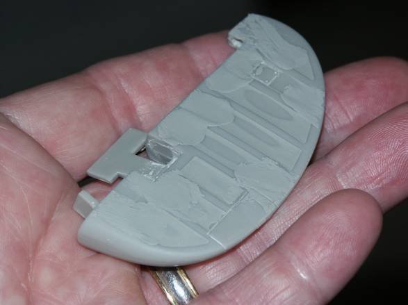
I then primed the sections.
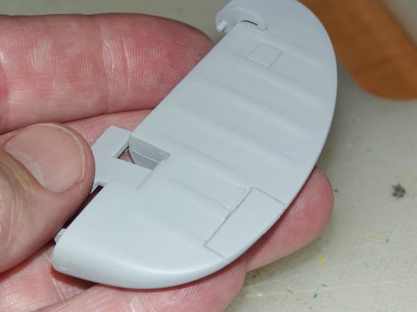
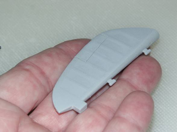
The final effect is a bit more realistic for fabric covered sections.
© William Joyce 2008
This article was published on Wednesday, July 20 2011; Last modified on Saturday, May 14 2016