
Trumpeter's 1/32 F4F-4 Wildcat Part 6: "The Engine"
By Rodney Williams
On page five (5), of the instruction sheet, there are 3 steps showing in detail all of the engine parts and how they fit together. Like all of you modelers, I cleaned up all the parts, dry fit them together.
I began my "White Glue Assembly Technic", as I call it, by white gluing everything together. There are four main engine cylinder parts. I glued parts E-1 and E-3 together and the same for the other two engine cylinder sections, (parts E-2 & E-4). Next, I attached part E-19, which is the "push rod" section.
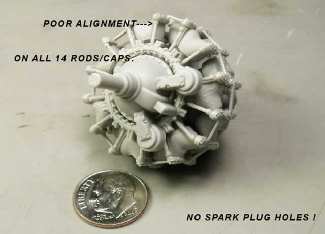
My problem began when I started to white glue on all the "push rod" caps, (parts E-8 and E-9). The caps went on ok, but the push rods did not mate up with the caps at the right angle. I doubled checked and made sure that I had assembled all the parts correctly (I did). I finished assembling the other parts which was the ignition ring, the prop shaft and the front hub, (parts E-5, E-24, and E-6).
In step four (4), the modeler repeats the above process of assembling the second row of cylinders. Again, I had the same alignment problems. You can not assemble some parts "wrong", because there are notches in parts like E-1, E-18 and the exhaust stacks which is part E-27.
Lo and behold my next problem begins with: "There are no spark plug holes". No problem so I think ! Just drill in the holes in the front of each cylinder (14 altogether). BUT WHERE DO YOU DRILL?
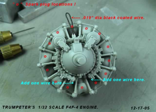
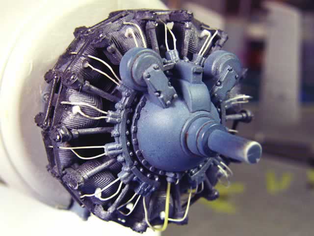
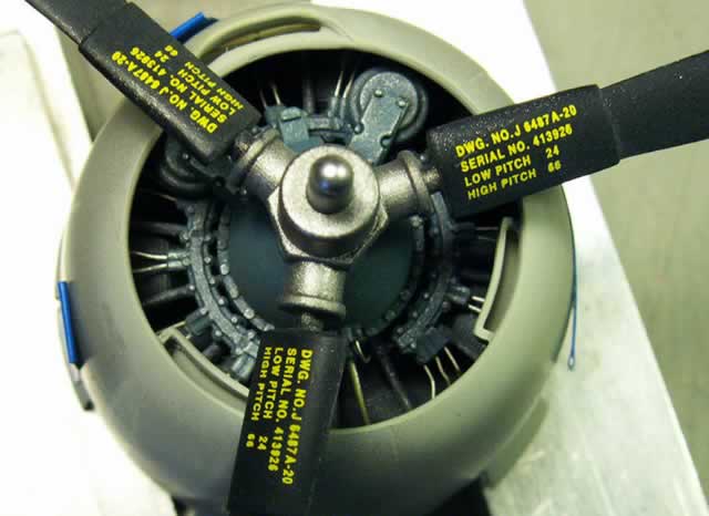
I have three F4F Wildcat books, and none of them really show any detail sections of the engine. Did the F4F-4 have the R-1820, and/or the R-1830 engine in it? I send out ""HELP EMAILS." I get several replies, and a couple of web sites to look at the engines. Now I find out that each engine cylinder has two spark plugs...WOW! I do my math, and come up with 28 spark plugs, and 28 ignition wires. GUESS WHAT? There are only 26 "stub-outs" as I call them on the ignition ring to attach each ignition wire. I re-count the ignition wires on three different engine photos...there are 28. I have to add two "stub-outs". I dissolve the white glue and then add the two "stub-outs" to my ignition ring.
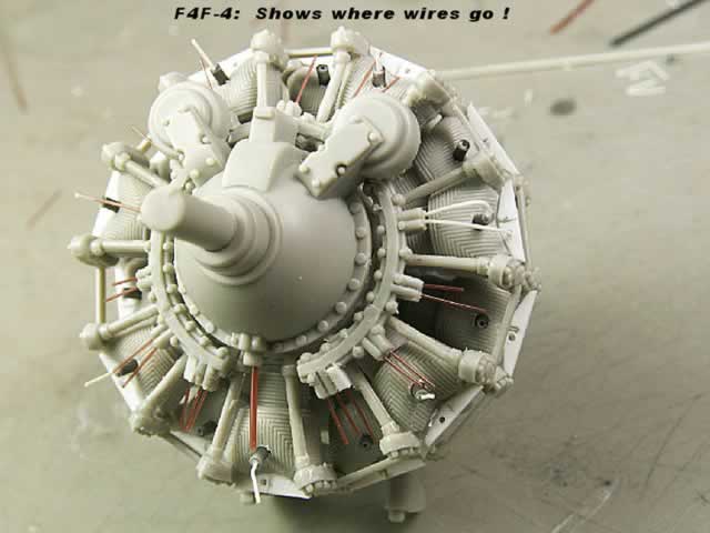
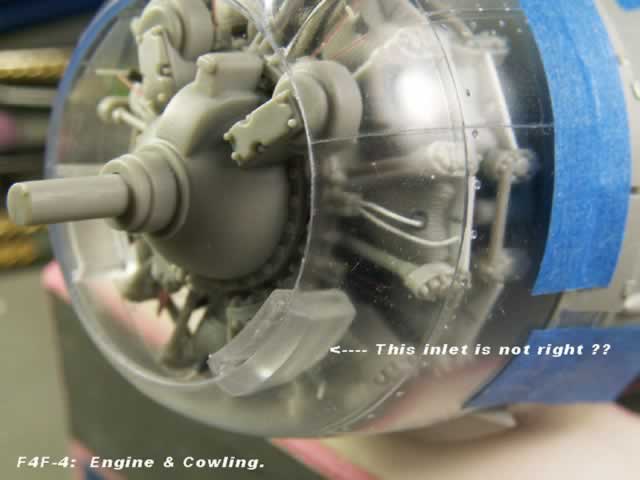
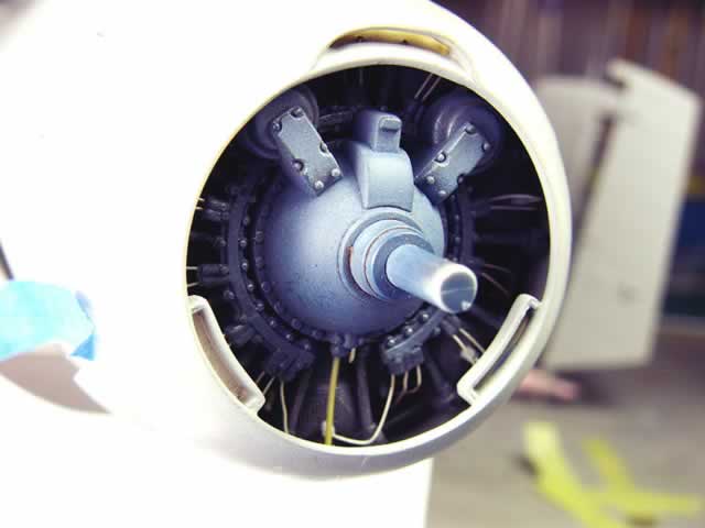
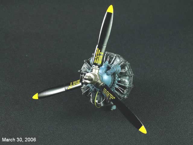
There is some sort of bracket that sits on top on each cylinder, where an ignition wire goes into, and to the back spark plug. I cut and fit some flat white styrene stock for all 14 brackets and super glued, (CA) them in (SEE PHOTO NUMBER THREE).
My client sent me the Eduard "PE" F4F set, which has some beautiful "FLAT" ignition wires. Sorry, but ignition wires were round during WWII. My advise to the companies that make "PE" parts is: If the real part was "round" and you can not make it round but you can make it flat...then do not make it flat...for me it is worthless...so don't spend the time and money to make flat parts, when they should be round.
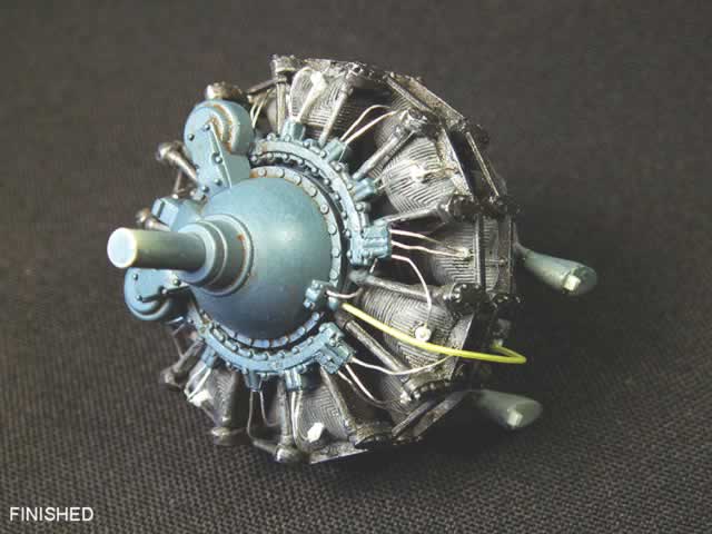
With all the problems solved, I dump the engine into water and dissolved the white glue, then use CA and glue it back together. I did not glue on the front hub and prop shaft, (parts E-6 & E-24) and the rear gear housing and ring, (parts E-18 & E-11). These parts, like the two assembled engine banks, will have different colors of paint on them. Once painted, I attach all 28 spark plugs and ignition wires. You can not see the back spark plugs, so do you really need to drill in the holes, then make the other 14 spark plug? Did I do it? Ask my doctor, he knows the answer!
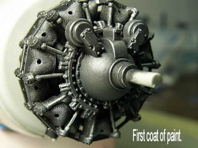
I used Tamiya Acrylic paint on my engine, then weathered it a bit with SnJ Aluminum powder, and some artist oil washes, (raw umber, etc).
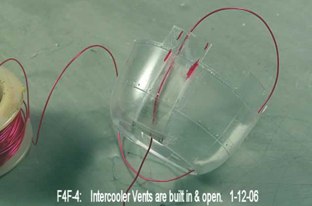
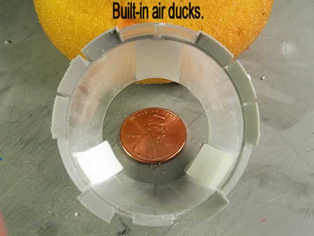
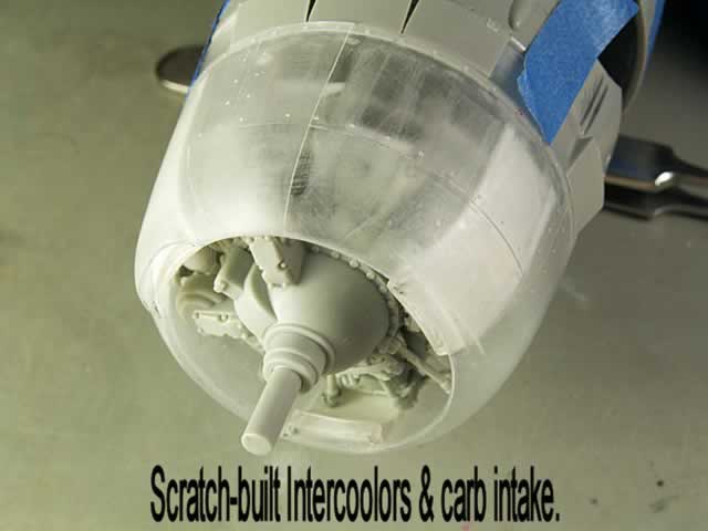
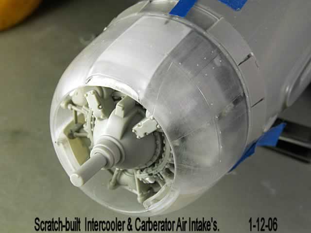
Next problem starts with the engine cowling's "Intercooler Vents". The enclosed photos tell the rest of the story. I just revised the molded-in vent openings, then added a flat vent tube made out of flat styrene stock. The red wire shows that the vents are open. I built in the vent on top of the cowling which is the air intake to the engines carburetor (?).
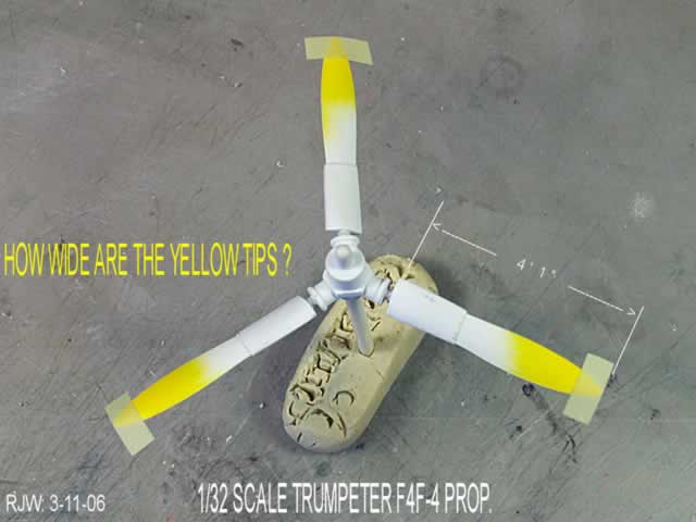
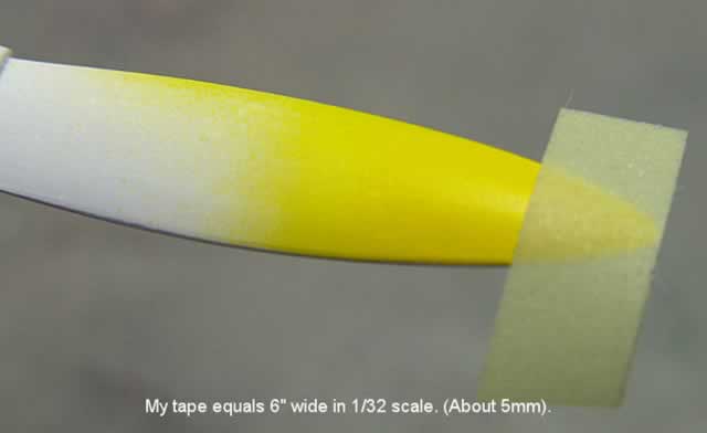
The prop was just sanded and painted. I guessed at the length for the yellow tips by just looking at real WWII photos. I always paint my props and/or other parts with white paint first before I apply any lighter color such as yellow, light blue, red etc. The white paint lets the true color come out for your other paints. Most important is: You do not need to apply tons of yellow paint over a gray plastic, nor over olive drab plastic and/or over olive drab paint. I learned all about this way back in 1987.
My next story deals with the fuselage...
Part 1: The Left Wing | Part 2: The Tail | Part 3: The Right Wing | Part 4: The Cockpit | Part 5: The Wheel Wells | Part 6: The Engine | Part 7: The Fuselage | Part 8: Finish
Happy Modeling!
© Rodney Williams 2006
This article was published on Wednesday, July 20 2011; Last modified on Saturday, May 14 2016