
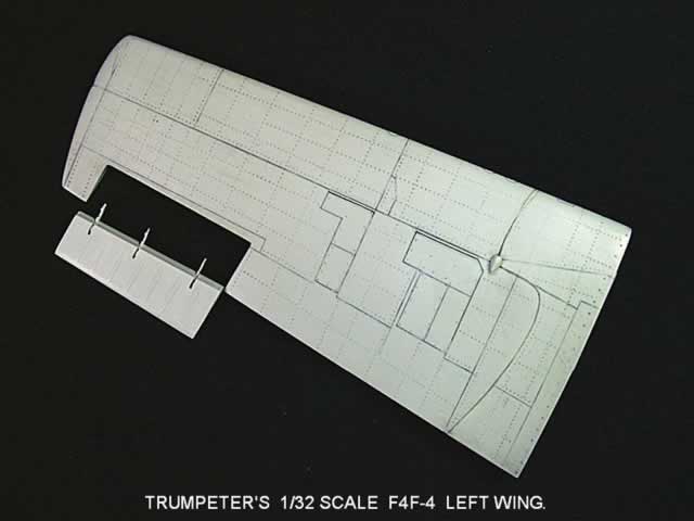
Trumpeter's 1/32 F4F-4 Wildcat Part 1: "The Left Wing"
By Rodney Williams
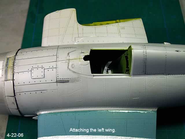
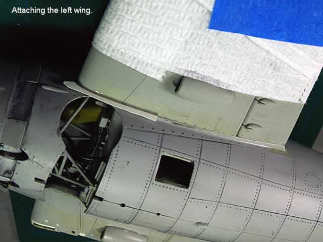
This project started back in November, 2005. I bounced back and forth from one building project to the other. When you see the photos showing the attachment of the left wing to the fuselage, you will note that the cockpit is in the model, but we have not addressed how it got there.
My client sent me a few model reviews of Trumpeter's F4F-4. One such review was: "I spent about 25 hours building my model." Since I more or less agreed to build this model "OOB", I said to myself...WOW ! This is going to be great. I surfed a few model web sites, however most of the modelers who sent in their stories did not address the problems that I ran into when I built this model.
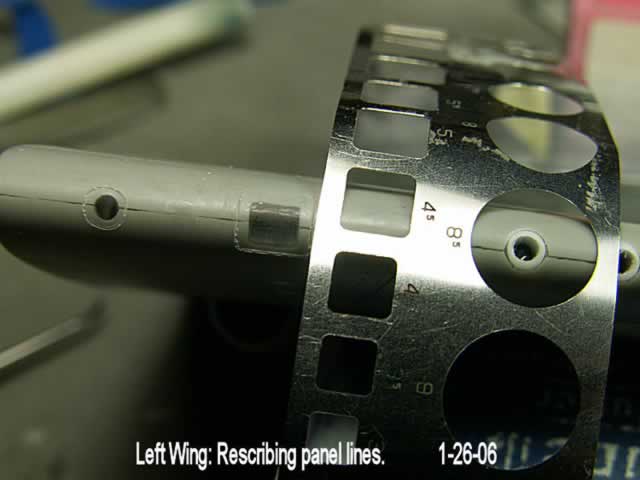
I began working on the left wing as it was to be in its flight position, (down and locked). I have added several statements on the photos, which helps the photos "tell the story."
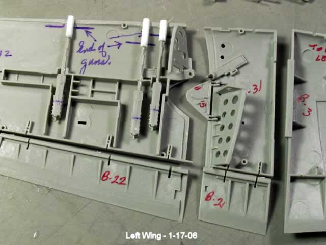
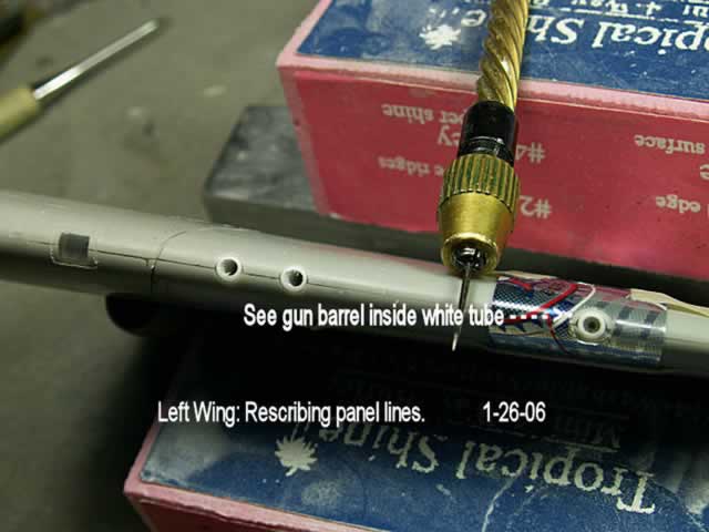
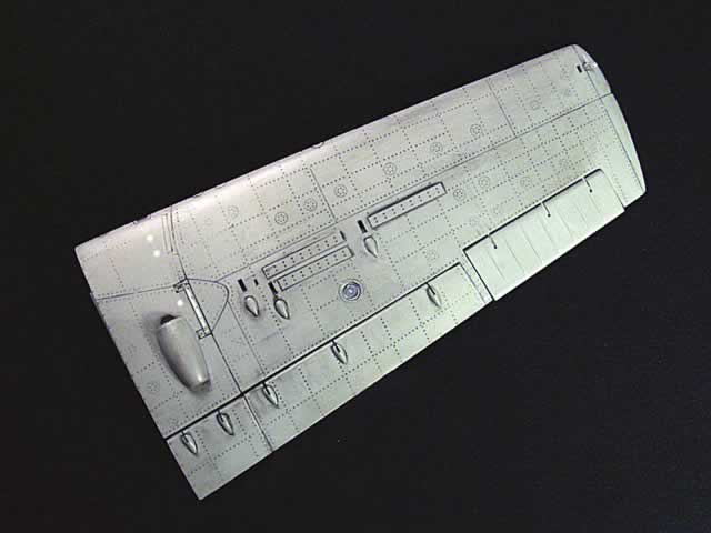
I enlarged the gun barrel openings on the leading edge of the wings, so that when you look into the opening, the gun barrel is centered properly. However, on the F4F-4 the gun barrels are recessed quite a bit, thus it's hard to see them. If I were building the model for myself, I don't think I would add them to the model unless I planned to open up the "ammo" compartments.
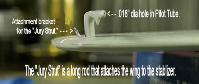
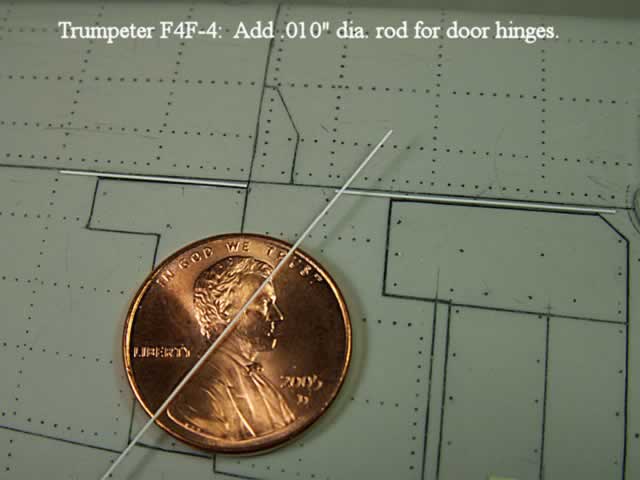
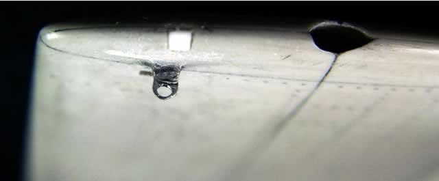
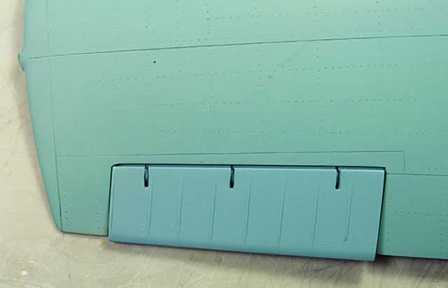
With a bit of research, (looking at the photos in the Wildcat books) I used some flat aluminum stock and hand crafted a new attachment bracket for the so named "Jury Strut." I just cut out a hole in the lower wing tip and slipped in the finished bracket, then filled the area with "CA" (super glue). When the Wildcat's wings were folded, there was what they call a "Jury Strut", that attached to the wing tip bracket and to a similar one on the leading edge of the stabilizers'. (see the "Tail" section of photos for additional views).
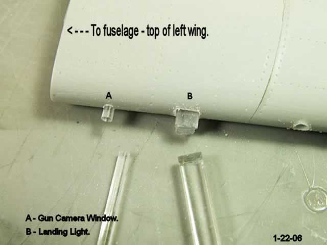
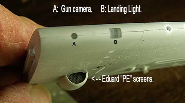
My photos show how I cut and drilled in holes into the leading edge of the wing for the gun camera and approach light. I just use some clear plastic rod and bar stock that I have had for a couple of decades. It's glued in place, then sanded down to about 1500 grit wet/dry sandpaper. On final assembly, these clear parts will be hand painted with a tiny bit of Future Floor Wax, which is called Klear in other countries.

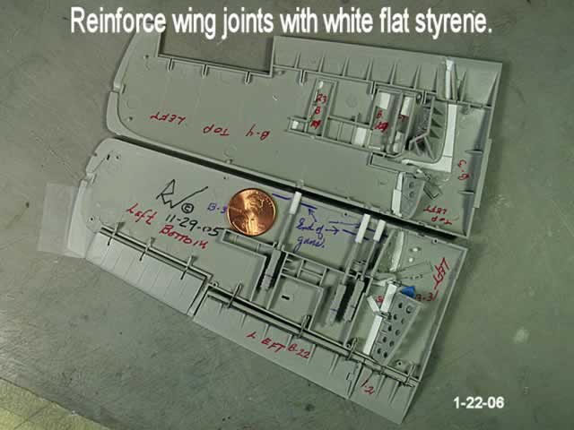
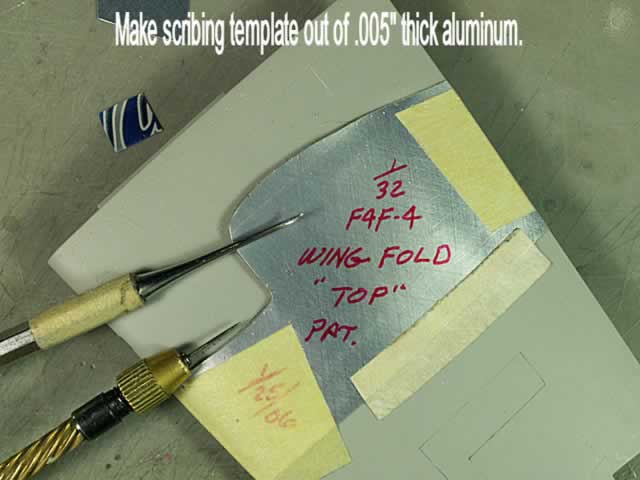
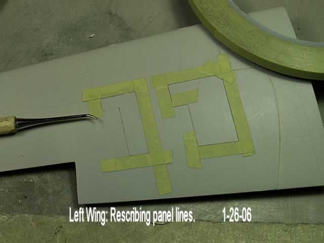
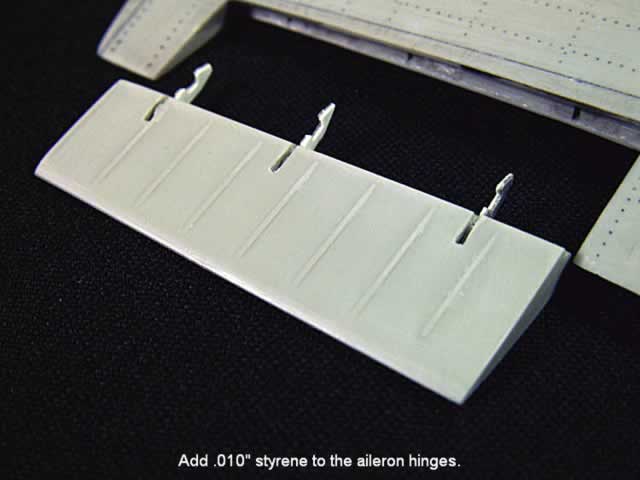
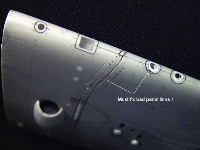
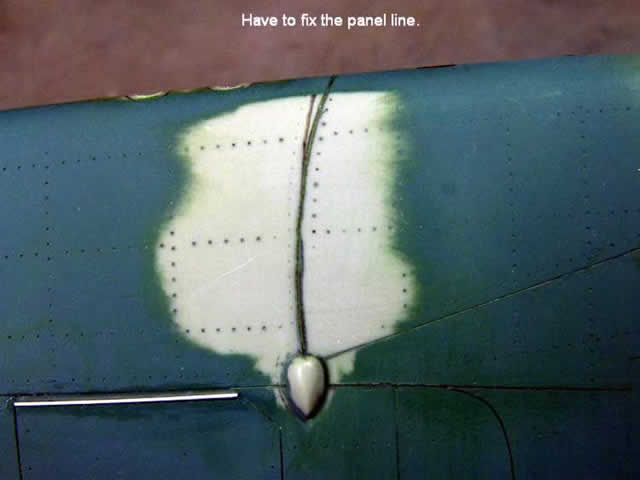
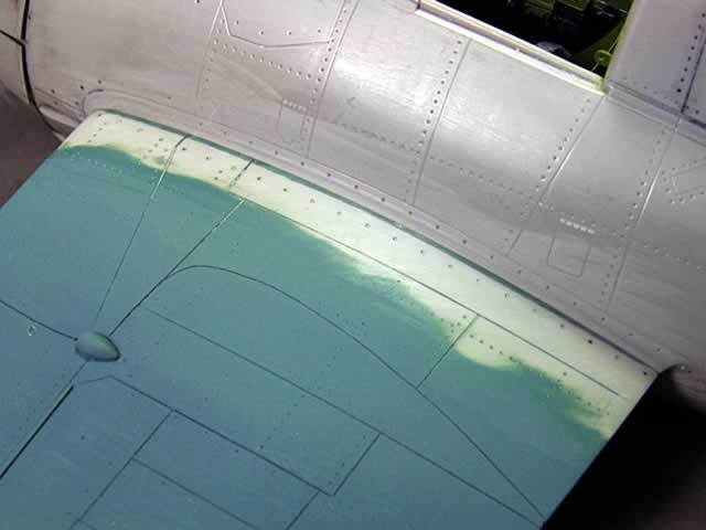
As usual there are gaps, seams, panel lines and rivets to be fixed and.or replaced. Long ago I learned to use .005" aluminum can metal to make my own scribing templates. Go for it !

That's about it for the left wing, so now I take you to the second segment, which is the "tail" section of the model.
Part 1: The Left Wing | Part 2: The Tail | Part 3: The Right Wing | Part 4: The Cockpit | Part 5: The Wheel Wells | Part 6: The Engine | Part 7: The Fuselage | Part 8: Finish
Happy Modeling
© Rodney Williams 2006
This article was published on Wednesday, July 20 2011; Last modified on Saturday, May 14 2016