
Airfix 1/24 P-51D "Dallas Doll" Part 2
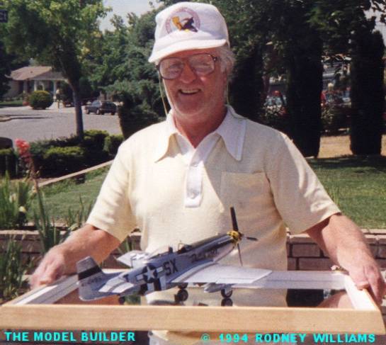
By Rodney Williams
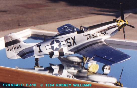
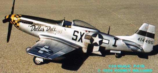
"Dallas Doll"
A P-51D Mustang in 1/24th scale part 2
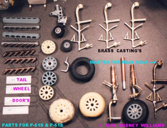
The main gear yoke, and torque links presented a problem! How can I "HAND-CRAFT," four identical sets for two models. It's impossible in my way of thinking, as I do not have any sophisticated tools, (eg: machinist lathe, etc.).
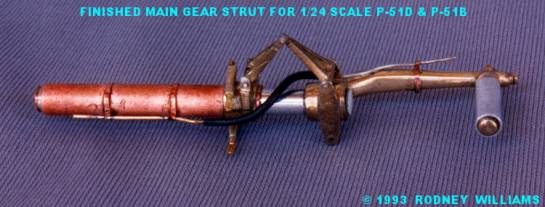
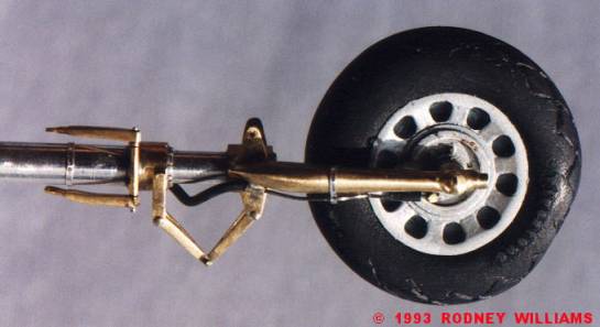
I got the bright idea to use all my photos of a P-51D Mustang I had photographed at the San Jose, California airport. I took along my tape measure, and spent the day making drawings of the wheel wells, and gear assembly. It was cut and fit all the way. When I got done, I felt I had a gear assembly that was very close to scale, and looked like the real thing. I had a jeweler make the RTV mold and cast the parts in brass. For alignment, the torque links were put together on a pin and hinge system. Therefore they could be moved up and down, as the oleo strut would telescope up into the main part of the strut.
From November, 1993 to July, 1995 my five part story for my P-51D to the P-51B conversion was published in the IPMS/USA JOURNAL magazine. In Part-II, I had posted professional quality drawings for said torque links, and gear assemble. These drawings will be on this site sometime in the future, when I do the story for the "B."
I advertised many parts for sale, which were expensive. I had no buyers, so in 1999/2000, I gave/sold all of my masters etc. Recently, a modeler wrote and wanted to buy the parts, stating he felt the price was too high a few years ago but now wanted them. He's a "day late and a dollar short" as we sometimes say in American English! I emailed him with the bad news.
I had several items for sale besides the complete gear assembly, including the tires, rims, prop blades, windscreens and canopies for both the "B" & "D" models. I have "0" today, except the mold for the "Dallas Style" canopy.
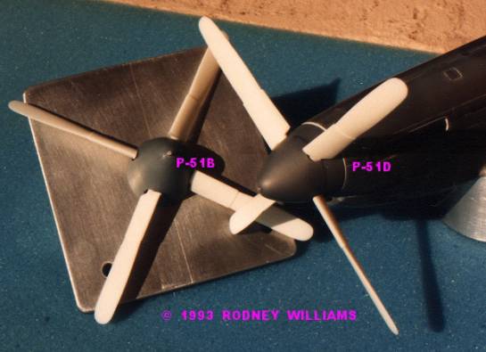
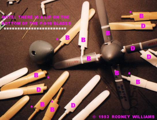
Looking at the prop blades on the P-51B and P-51D, I noticed that the cuffed blades on the "B" had some sort of protruding plate on the bottom of the cuff, where it fit's into the spinner. I made a note on my prop photos!
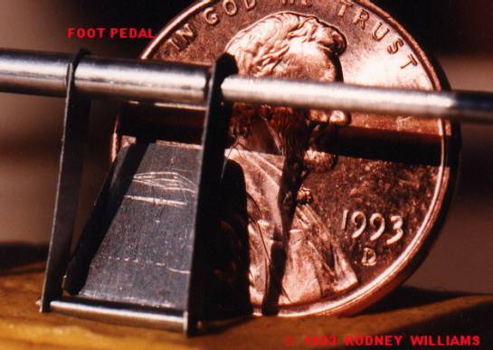
The foot pedal's were merely fashioned, using the .005" thick aluminum from cola/beer cans.
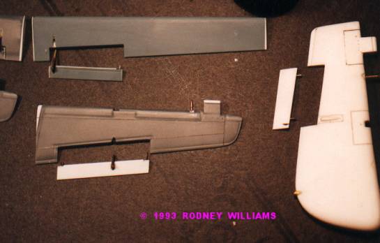
These photo's of the aileron, elevator and rudder show's my revisions. The kit rudder was not correct, so I built a new one. This was a lot of work, so I revised the rudder for the P-51B.
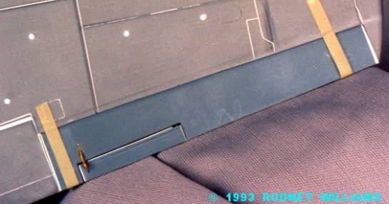
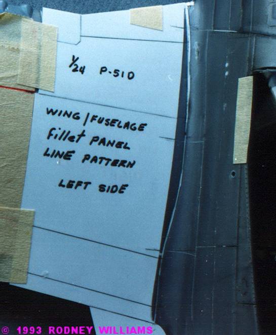
When I was at the airport doing my photography, and measurements of "ALL" the panel lines on the P-51D, I made a scribing template for the top of the wing, where it meets the curved wing fillet.
The Airfix kit has many flaws, but let us not knock the manufacture. Even today!, many kit's have some fit/panel line problems, etc. If you are an "advanced model builder like me, you can fix anything." The moral of the story is:
"AT LEAST THERE'S A KIT TO START WITH AND YOU DON'T HAVE TO SCRATCH BUILD THE WHOLE MODEL."
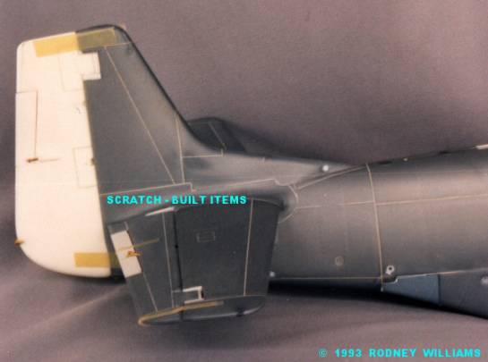
As you view my photos, you may wonder what the round .062" diameter white rod's are for? They are placed into the wings, and fuselage for wing/fuselage alignment and stiffener's. On the Airfix kit, all the panel line are way too wide and to deep. Some were in the wrong place. I just corrected the problem by filling in all said panel line's with super glue, then using my scribing tools to re scribe them back in. I would say that even on a 1/24 scale model, the panel lines would not be more than three to four thousand's of an inch wide, nor the same in depth.
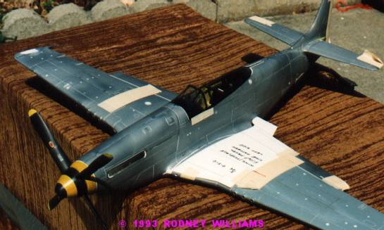
What a model this turned out to be! With a few thousand hour's, it is finished in all its' "glory." I like it, and so did my client, which is most important! If you ever build a model for a client, remember he is the boss, he is the person paying you the money, so you build, and paint
it to his specifications.
Case in point: At the beginning of the article, you viewed an "art drawing," with the aircraft's name on both sides! Most World War-II aircraft I've viewed in book's only have the name on one side! Since we had only one photo of it, viewed from the left side, we are not sure if the name was on both sides. Is it right, or wrong? It was right for my client Frank, and that's all that counts!
 I painted the cockpit interior, the wheel wells, etc. with the "yellow - green" chromate paint. I sent samples to Frank showing the two chromate colors. He choose the "yellow - green," over the "dark - green." It, was what Frank wanted!
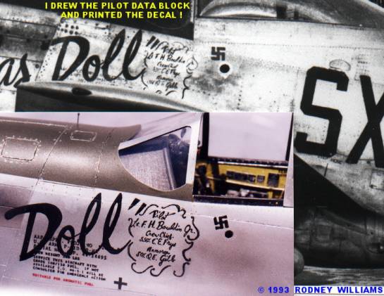
"HOW TO MAKE THE PILOT ART WORK?"
I've always been a darn good artist since I was a kid. I could draw anything! I took the real photo to the copy center and enlarged the area to about 6" x 6". I used tracing paper, and drew on this pilot data block, or what ever you want to call it! When I was happy with my work, it was back to the copy center and I reduced it down to 1/24 scale. I just printed it on clear decal film paper using my home/office copy machine. On that old copy machine, the black/red powder would not stick very good to the decal film. I experimented!!! I coated the clear decal film with Future Floor Wax! Presto!!, the powder stuck. I applied more Future on top of the black and red powder to seal it. Now day's with all this fancy computer software, it becomes easy.
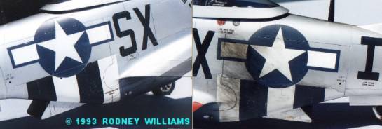
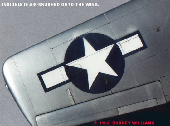
I love the challenge of painting on the aircraft's name, the insignia's and the identification letter's. I used the above process to make the name of "Dallas Doll," and the "SX I." letters. I use artist low tack "Frisket Film," for my masking material. INSTRUCTION'S SAY: "Apply the film, then paint as soon as possible, and remove the film!" If you leave it on too long, the adhesive will stick to the model, which can be removed with "Mineral Spirit's," which will also remove the "SnJ" aluminum paint, but not Tamiya brand paints." Or, it will pull off the paint down to bare plastic. ( Have your painting equipment ready to use, including your paint!). Apply the film, and lightly burnish it down along the edges. I used "Tamiya" flat black, blue and white paint, and let them dry for about 5-10 minutes, then remove the film.
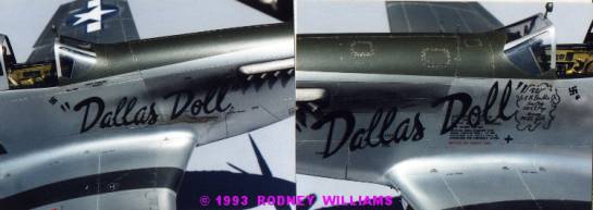
I painted the blue first for the insignia's. Within no more than twenty minutes of spraying on the Tamiya, you can pick, scrape, and chip off area's of the paint. Most times it will not remove the "SnJ" aluminum. Some practice is in order! After they dry for a few days, I lightly sand them with 2000 grit wet/dry sandpaper. This sanding removes the rough matt finish slightly. I also rub down the area (insignia, etc.) with a soft cotton cloth. I re-mask for the white bars and star, then paint them on. I repeat the above process for the white paint.
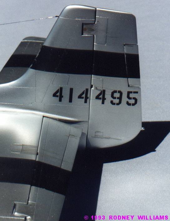
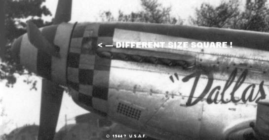
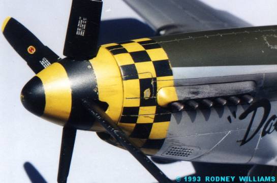
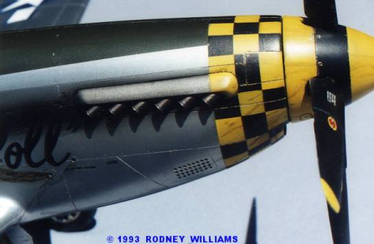
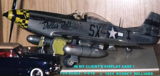
Take a good look at the close-up photos of the yellow and black squares behind the spinner on the model. What do you see? One square is not the same size as all the rest! Did I do something wrong? Now look at the black and white blow up photo of this section of the real aircraft! You must pay attention, and study the photos of the real aircraft. I took this model to my club meeting with the photograph. Yeah! a modeler said: "Hey Rodney, you screwed up, this one square is wrong!" My reply: "Look again man!"
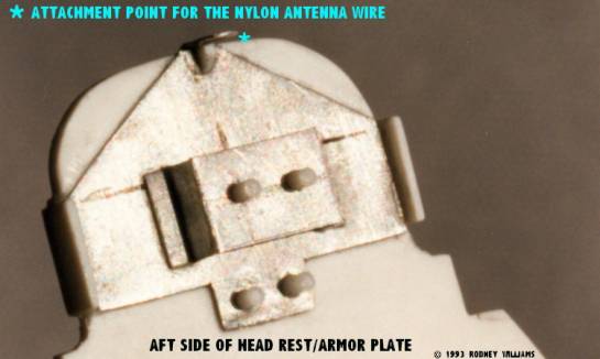
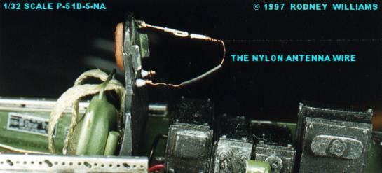
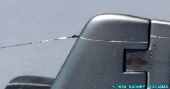
I was going to tell you how I make my antenna wires, using women's black nylon panty hose! For now, all you get are three blow up photos! One shows the back side of the unpainted head rest. The second one is of my 1/32 P-51D-5-NA, painted head rest with the wire attached. The last one is of the painted rudder fin with the wire attached to my hand made "eye" anchor bolt. (WHY?) If I write down how I do it, and have no photos to show you, then you will not be able to do it. I plan to write about it, and take "in progress" digital images, then I will send it to this web site.
The nylon wire is tied to the bracket on the back side of the armor plate head rest, in a pre drilled hole and super glued! The excess thread is cut off with a "new" No. 11 blade. The other loose end of the wire is threaded through the canopy and taped somewhere on the fuselage and/or on the rudder fin. I move the canopy into position, and pull the nylon wire, through the .010" diameter hole in the canopy at the same time. The canopy is "always" glued in place with white glue, or Future Floor Wax. Once the glue on the canopy is dry, (One to three days) I push the loose end of the nylon wire into a pre drilled hole in the anchor bolt which is in the rudder fin. The wire is carefully stretched to its' maximum, and held there using tweezers. I wrap the nylon wire around the anchor bolt and apply a "micro" dot of super glue with a special made super glue applicator. Now I have to be very careful in cutting off the excess thread. One tiny miscalculation, and you may cut the whole antenna wire off. If this happens, off comes the canopy and you start all over.
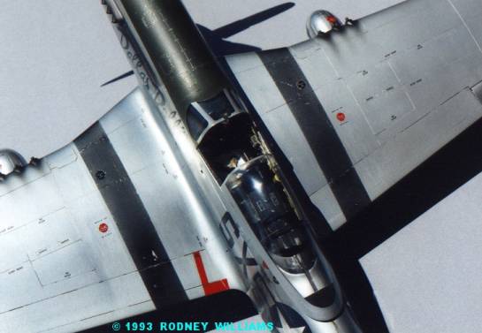
For some reason I do not have any good photos of the cockpit area on the finished model. These two photos are it!
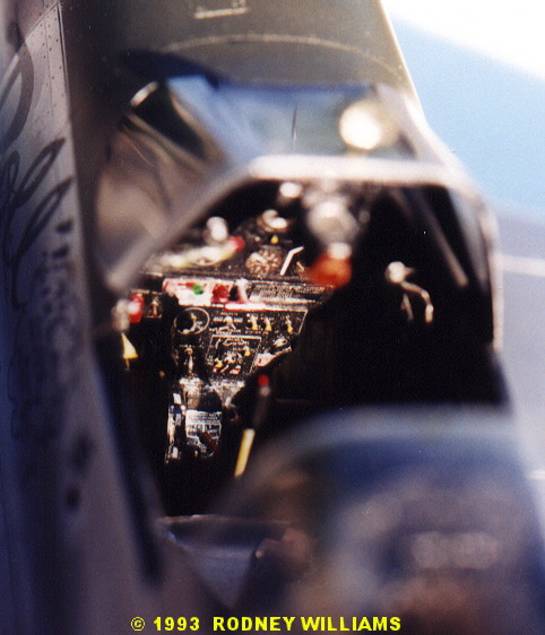
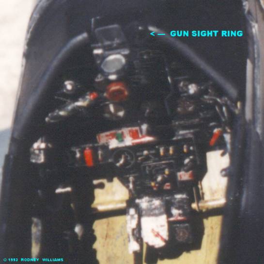
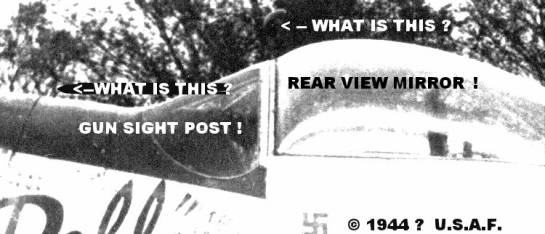
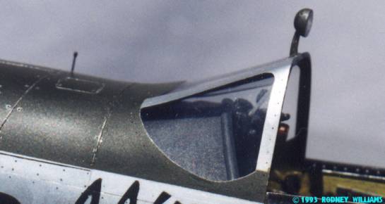
Take another look at the black and white photo of the complete aircraft! I noticed a "half moon white curved outline" above the windscreen on my original 8"x10" side view photo. (For some reason it does not show up on this scanned in image!) I re scanned a section of the photo, then lighten it up considerable with my p. c. software, so you could see what I found! It's the rear view mirror. Then I noticed something vertical in front of the windscreen! It was the "gun sight ring post," mounted on the right front section of the fuselage. I read that most all U.S. fighters had a movable gun sight ring inside the cockpit. It would be deployed if the "reflector" gun sight failed. Therefore they had to have the post mounted forward of the windscreen, so when the pilot looked through the ring sight, he could line up the enemy aircraft on the post bead, then pull the trigger! As a professional photographer for decades, I look for little things like this.
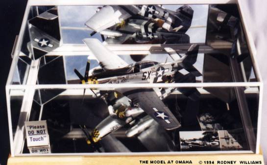
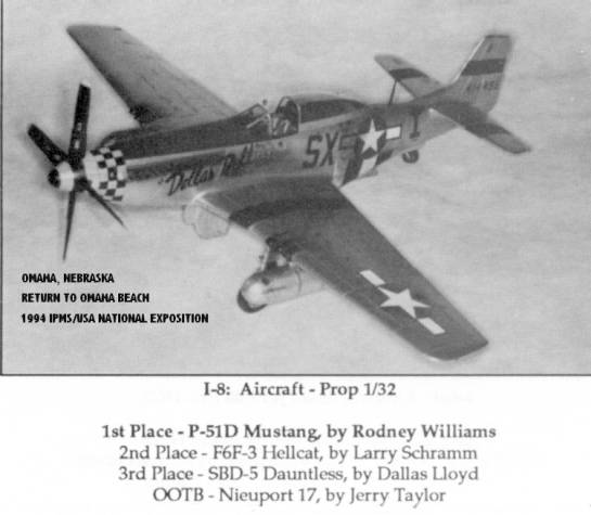
I made a large display case for the model. It also had a back mirror, with two 45 degree angle mirror's. This is how I displayed my client's model at the IPMS/USA Omaha Convention. I remove the cover for the National Judges, and some picture taking modelers!
This is "DALLAS DOLL!" I hope you like the show? Down the road, I will present the 1/24 scale P-51B converted from the Airfix "D" kit, and a 1/24 scale FW-190D9 "DORA converted from the Airfix Fw 190A kit.
Any comments and/or questions are welcome! However, I may not be able to answer some questions in detail. It's been too long ago since I built the model, and I did not write down any data as to material used, it thickness, etc.
For you advanced modelers like me, all you have to do is look at the photos, then start cutting and fitting them together. After 3,000+++ hours, you should be done with your model!
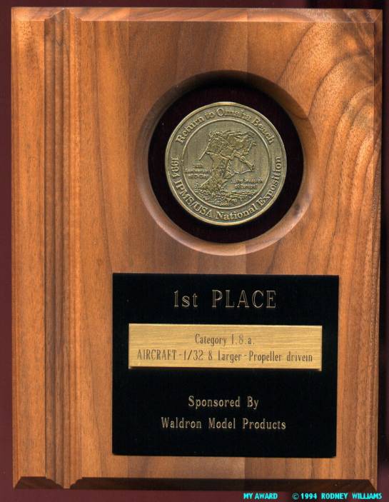
P.S. I won first place in Omaha. It, like other models of mine have been nominated for "Best Aircraft," but did not win! They say: "You can't win them all."
© Rodney Williams
This article was published on Wednesday, July 20 2011; Last modified on Saturday, May 14 2016