
Trumpeter's 1/32 F4F-4 Wildcat Part 5: "The Wheel Wells"
By Rodney Williams
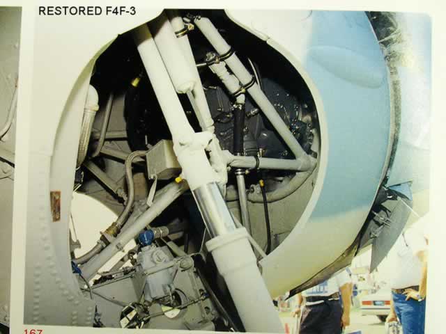
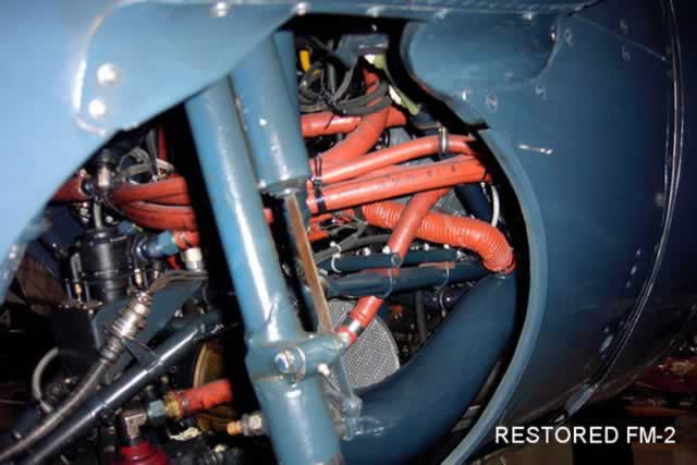
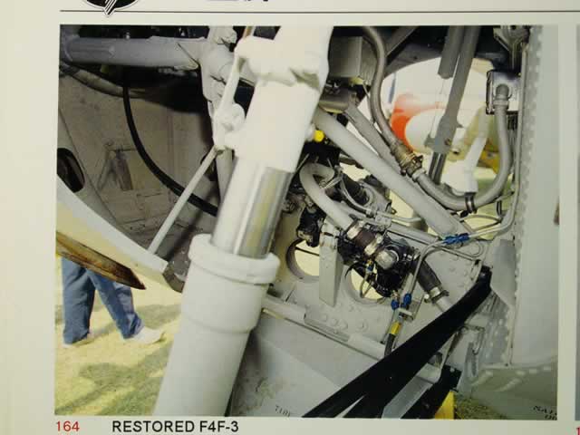
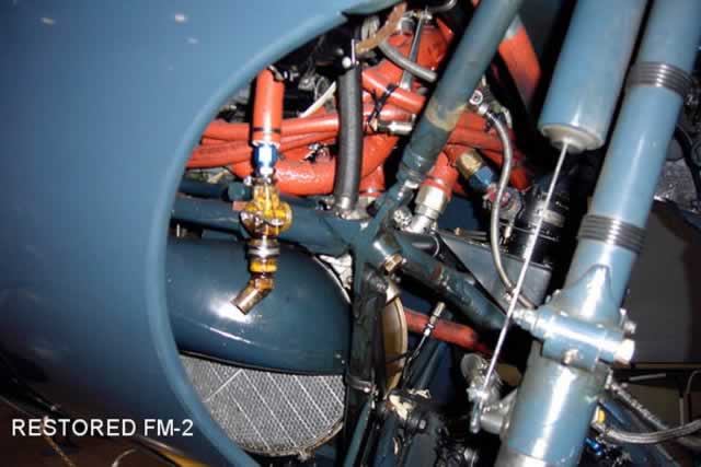
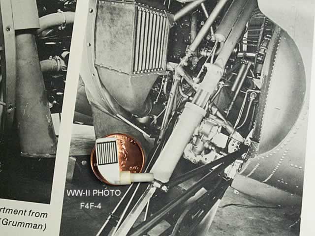
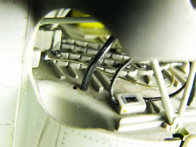
The first four color photos shows the left and right views of two restored Wildcats. Look at the plumbing differences. What a mess you have to deal with on the FM-2. The caption on the WW-II black and white photo says that this is a F4F-4. The intercooler box does not look like it is in the F4F-3. If it's in the FM-2 it's all covered up. I tried to find other photos, so I would know where the tube goes that's on the bottom of the "Intercooler" box.
Eduard's "PE" box was not a complete box, so I built my own and just used their screen. I cut off most of the tube as it was hitting the front of the engine mounting brackets.

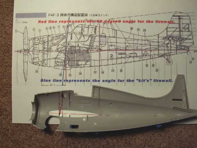
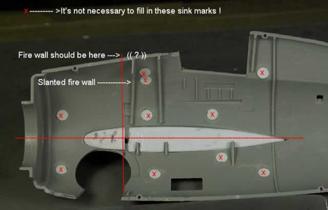
In many of my stories I always say: "Never trust any art drawings by any one, unless it's a factory drawing". The "cut-away" side view art drawing on page 71 of the Aero Detail 22 show the F4F-3. Item #8 is the fire wall, which is vertical to the horizontal fuselage line. My question is two fold: Was the angle of the fire wall changed from the "dash three" to the "dash four", or is the drawing wrong?
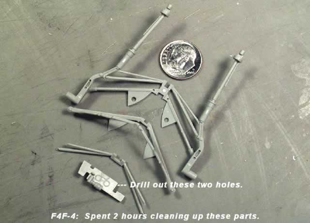
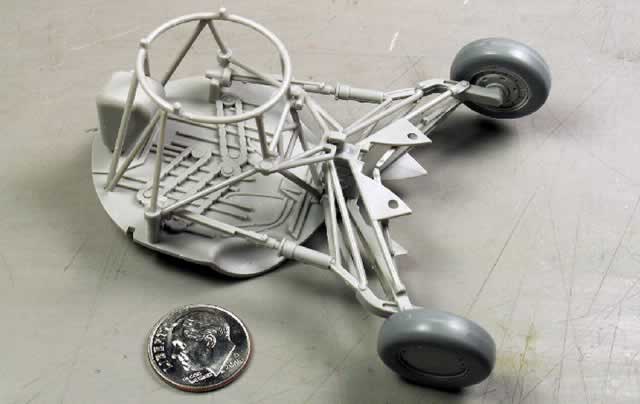
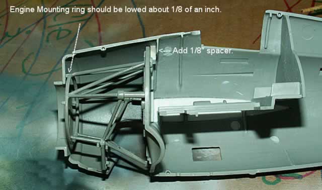
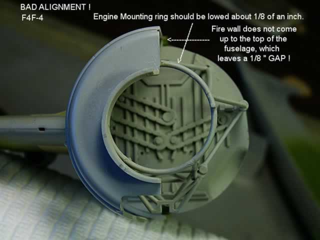
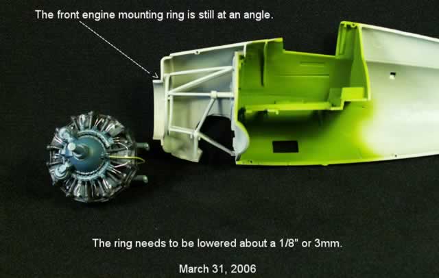
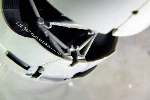
Step 6 on page five shows how to assemble the "Main Gear Cabin Assembly." Once my white glue was dry, I fit in the assembled section, which fit into a notch, ( Step 10, page 7). Other modelers mention that there is a big gap at the top. The engine mounting bracket was slanted upwards...WOW!...I chose to push the top of the kits fire wall forward by about 1/8", thus the front engine mounting ring looks better, but still needs to be lowered more. I pushed the top of the fire wall forward until the mounting ring met the front open section of the fuselage. The fire wall in now about 1/8" or more into the area where the wheel would fit when the gears are retracted. This can not be !
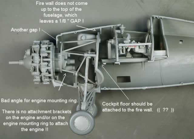
Go back and look at my second color photo of the restored F4F-3. You can clearly see the the engine mounting ring fits right up to the front wall of the fuselage. You can see that the aft engine housing, (part E-18) slips into the hole, and that it is secured to the mounting ring, (part E-20). To lower the front engine mounting ring more, I would have had to revise both bottom side fuselage sections where the opening is for the wheels. Then the fire wall would have to be pushed forward another 1/8" so that the forward mounting ring would fit up against the front fuselage plate. Or leave the fire wall as is, then add about a 1/4" to the 8 tubes that hold the mounting ring in place, ( part E-20). The whole damn thing is dead wrong.
I have read several stories on the model web sites concerning this F4F-4 model. Not many of you mention anything about the problems I am having with this kit. Did I get a bad kit or what? Just look at all my photos, they will tell it like it is.
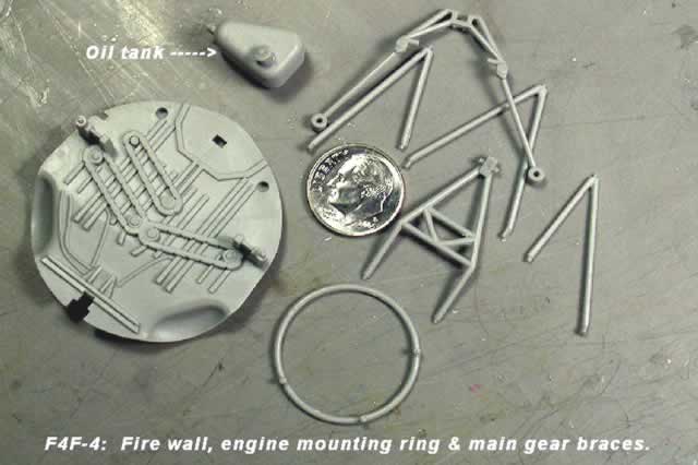
The oil tank color was to be black. I contacted Chris Novak over in Germany. He said that they were usually painted the yellow green chromate color.
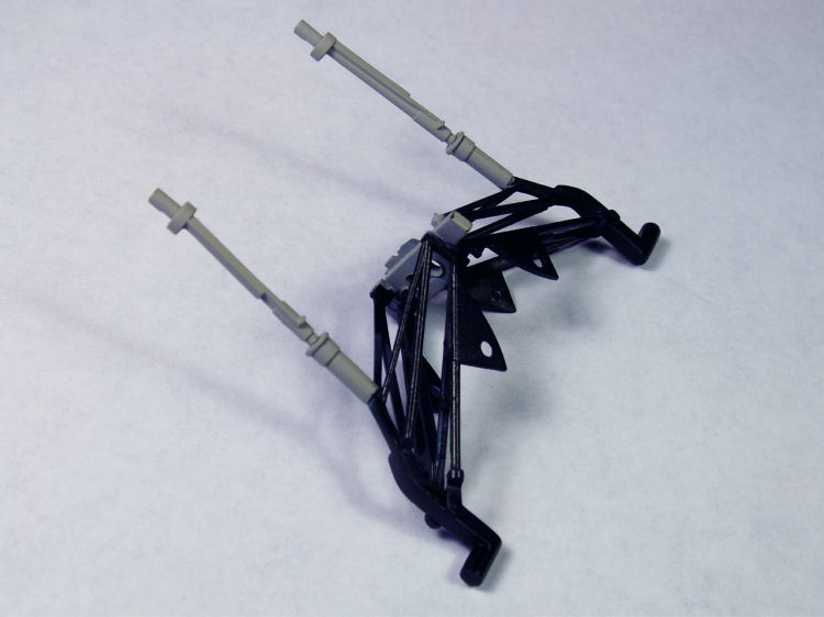
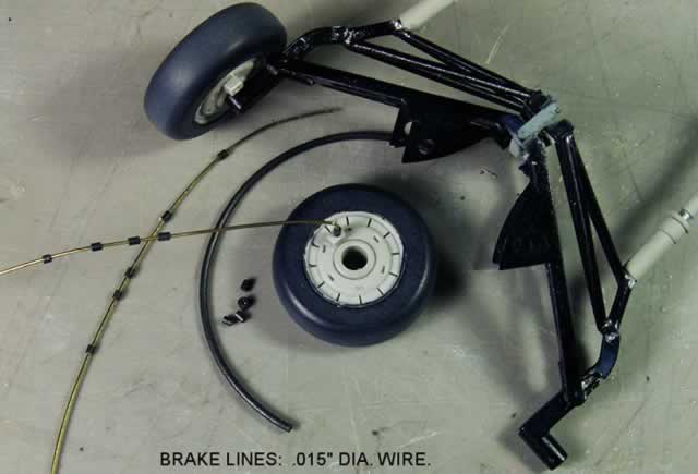
My client supplied the tires that I'm using on the kit. I removed the little hydraulic line brackets that I made and put on the rims. WHY ? When the tire was rotated, that bracket hit the axle bar.
Forthcoming is the engine.
Part 1: The Left Wing | Part 2: The Tail | Part 3: The Right Wing | Part 4: The Cockpit | Part 5: The Wheel Wells | Part 6: The Engine | Part 7: The Fuselage | Part 8: Finish
Happy Modeling!
© Rodney Williams 2006
This article was published on Wednesday, July 20 2011; Last modified on Saturday, May 14 2016