
21st Century Toys P-38J-15-LO “Lucky Lady” in 1/18 Scale – Part 2
By Jay Wheaton
Hello again, let’s move on with Lucky Lady. In Part 1, I went through the main landing gear build-up. Now let’s proceed to the main gear bays and see how far we can go.
I knew before I dug into the gear bays that I was in for a challenge if I did it up right. The gear bays for the P-38 are chock full of stuff – gear support truss structure, hydraulics, clamshell door cables and mechanism, turbo-supercharger intake ducts, radiator tubing, and electrical equipment with wiring. Initially I was going to ignore most of it – but the MLG turned out so nice I just felt I had to keep the quality up to that level. Plus – it would have been a shame to ignore some of the excellent diagrams and pictures of the door actuation mechanism available from the part catalogues etc. – it was a challenge I couldn’t resist. So I basically went sort of insane and attempted to include everything. You will see it – with the exception of a large complex air filter for the turbo-supercharger duct which I just didn’t know how to do.
First up was to Dremel away all the stuff in the existing bays that isn’t needed, and to cover up some holes. This gave me 4 decent walls and a ceiling – not real accurate but something to work with and something that fits into the booms.
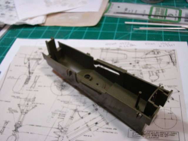
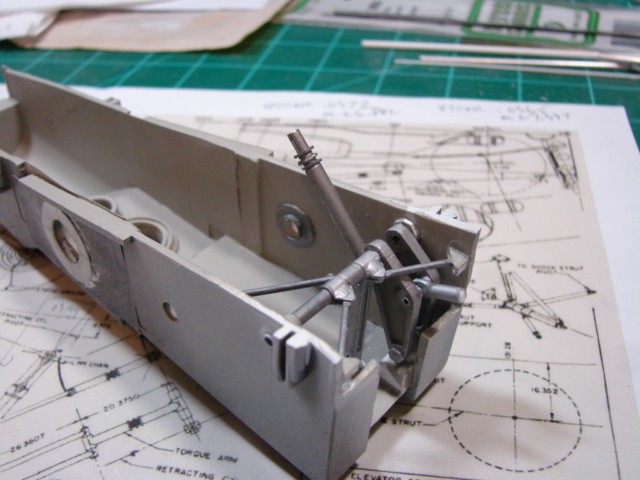
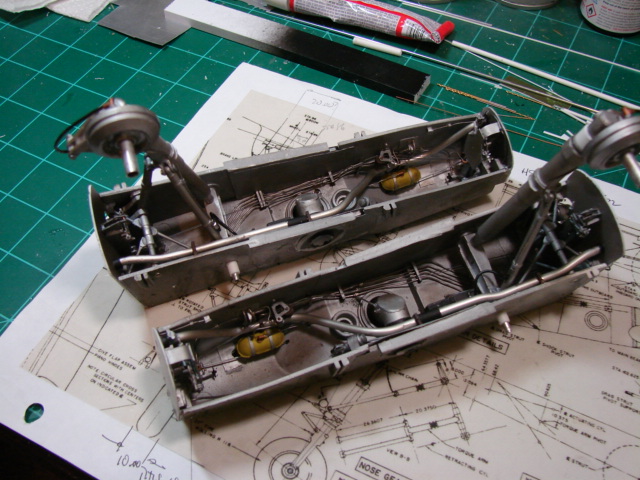
Then I fashioned a main landing gear (MLG) drag link support structure comprised of aluminum tubing, plastic tubing, and a couple of fancy end mill machined parts that help make up the drag link folding struts. In the background you can see diagrams of this which helped me immensely. And if you noodle the picture long enough you may figure out how the MLG extends and retracts:
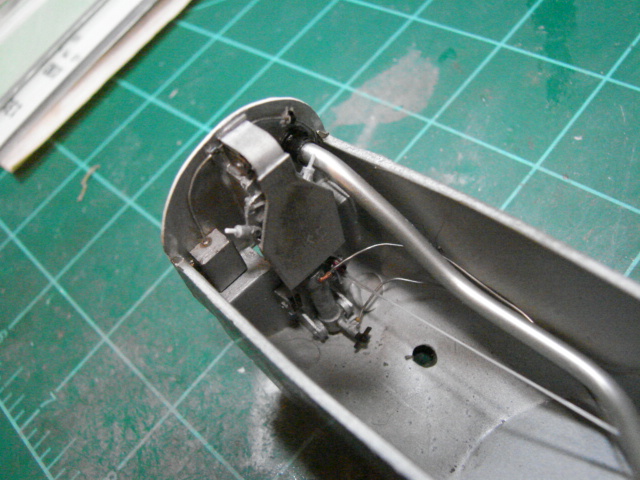
Then it was gear door mechanism. This requires a bit of explanation. In real life the two long clamshell doors are driven by a single hydraulic linear actuator mounted on the aft wall of the gear bay. The actuator rod extends down to open the gear doors by driving a trolley of sorts that slides on rollers on a track, also mounted on the aft wall. The trolley has two push rods directly attached to it – one for each door. They in turn attach to the aft end of each door and are easily seen. That is tough enough. But a slave actuation for the forward end of each door is actuated via a system of cables and pulleys. And that is the challenge.
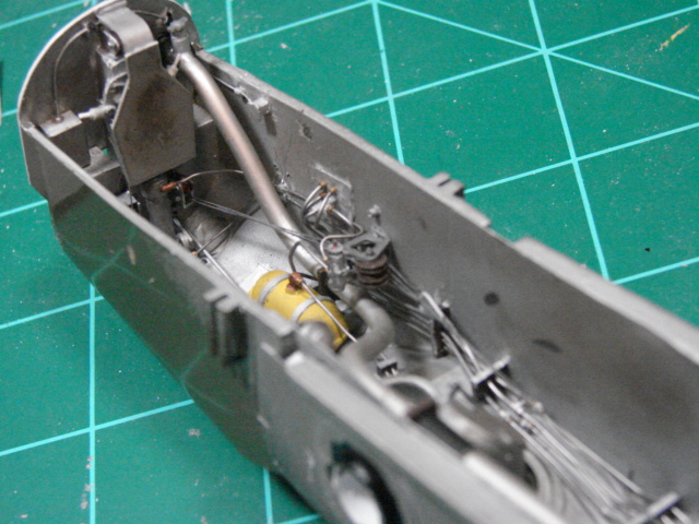
Here is a shot of the door actuator, trolley, track and some cables:
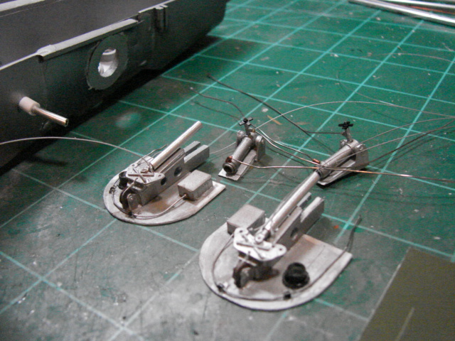
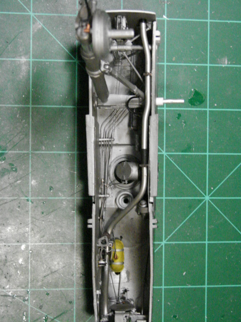
And the basically finished aft bulkhead. Note the radiator tube, made from .125 inch solder. That stuff is great – it scales about right and can be formed fairly easily:
The cables BTW are fishing line. Back in there is also a turbo-supercharger oil tank that P-38 experts know of. That was a fairly easy scratch build. Also there is a very very complicated pulley bracket for cable routing forward to the forward bulkhead. Take a look:
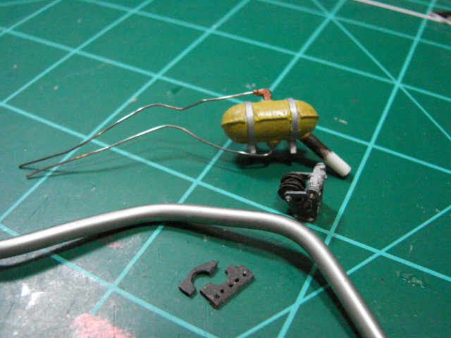
You will see hydraulic tubing associated with the door actuator, the cables routed through the pulley bracket, and two little pegs sticking up at about a 45 degree angle. Those are the rod ends for the push rods which drive the doors. In a later installment you will see how the opposite ends of the push rods attach to the clamshell doors themselves.
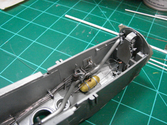
Then I struggled with the elbow ducts for the turbo intakes (no pictures), and the valve actuating mechanism. As already mentioned, they lack the complex air filter and associated ducting that in real life was there. And then the forward bulkhead with its trolley and track and pulleys. Here are some of the scratch built fwd bulkhead details:
Some blocky scratch builds for electrical equipment, some other miscellaneous stuff, and the left-hand (LH) gear bay was done:
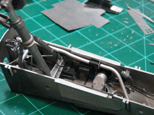
The MLG is final installed in those shots, because of the brake lines that attach to them and route in the gear bay. Very busy LG bays…
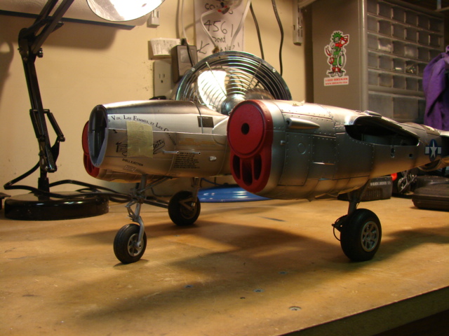
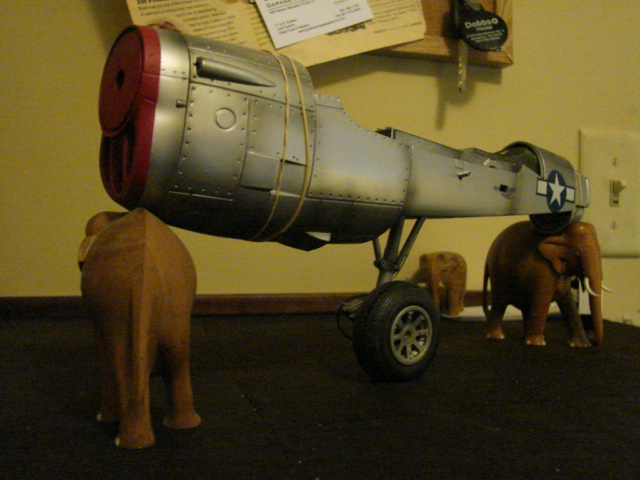
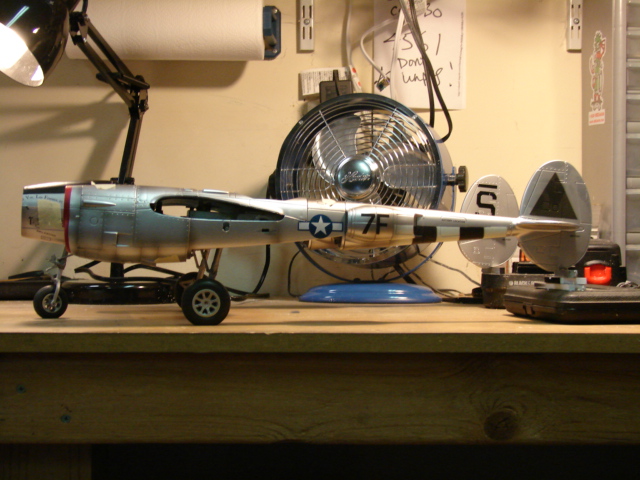
So what is it going to look like? The LH boom held up by elephants:
That LH gear bay took many weeks – the RH gear bay took almost as long. And time marched on. Finishing them both was a big milestone:
Next on the docket was the nose landing gear (NLG). By far the biggest challenge on the NLG was the shimmy damper, and I meant to have an excellent shimmy damper if nothing else! 1/18 scale allows this to happen, that and the lathe / end mill. Here is what I was looking for:
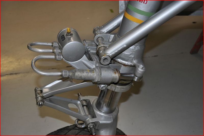
Not this:
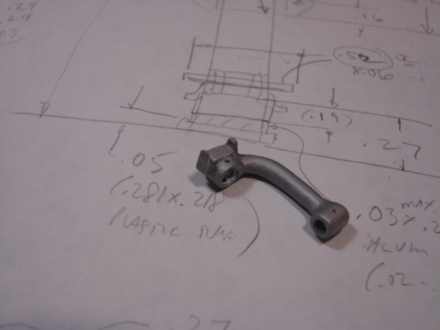
First there are some difficult machined fittings for the strut, somewhat similar to what was done for the MLG struts:
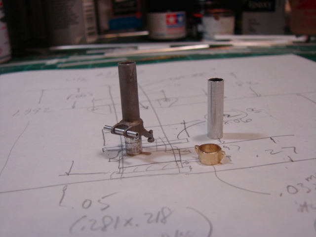
The lower strut had to be hogged out of a big piece of plastic – just hand work with Dremel, file, X-acto:
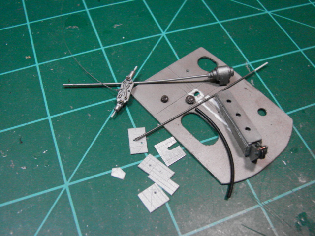
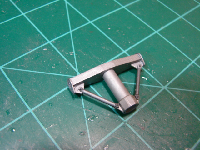
And (drum-roll) the shimmy damper mechanism:
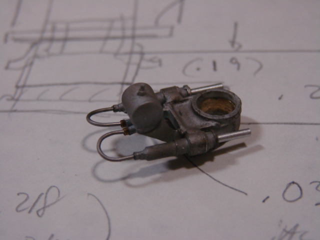
What I tried to depict is the pressurized air tank, lines to the cylinders, and pistons which engage little rollers on the strut fitting. The hard parts were the machinings of course, but the brackets for the air tank were tough little .005 inch think plastic flat patterns. And I mean little.
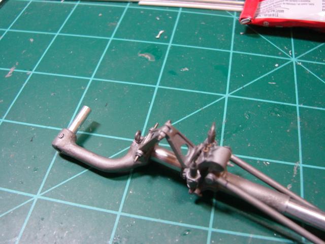
Here is everything associated with the shimmy damper mounted on the strut:
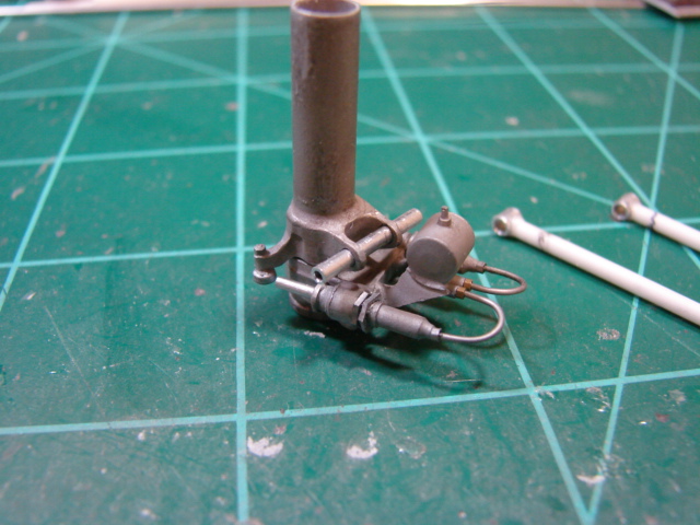
Note the misalignment – that is because the NLG will be turned about 20 deg. Here is the lower strut with the oleo attached:
Torque links were machined from plastic stock on the end mill – these were difficult to get accurate:
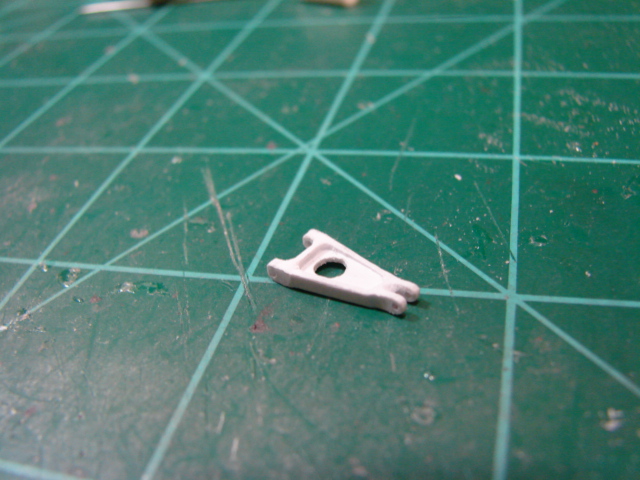
Of course there are two of these little tuffies – here they are installed on the strut. Note I used wire and little nuts for joint details to try to maximize realism:
The uppermost part of the strut is a triangle truss affair (for side loads) which required only some elementary scratch building skills:
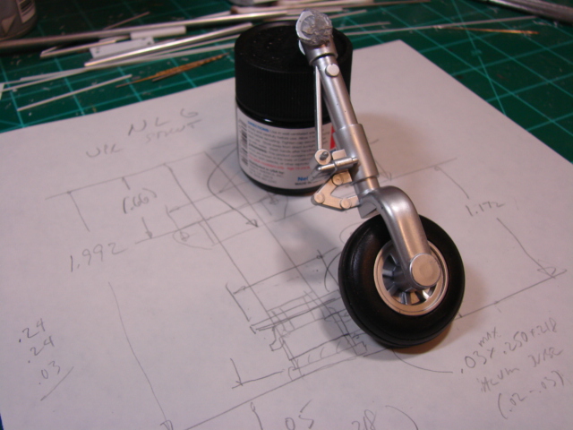
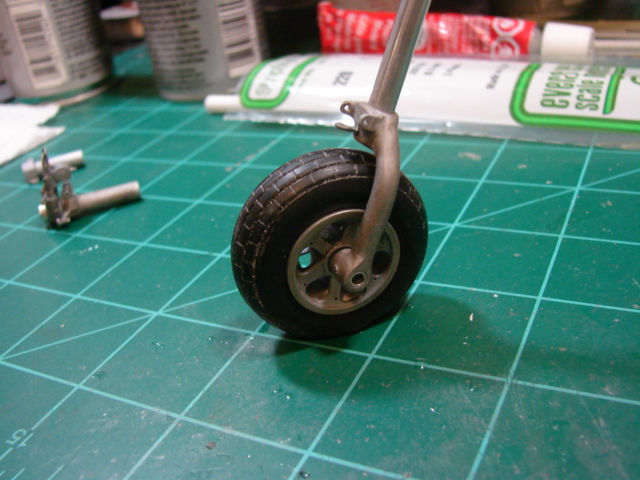
The pair of drag links were relatively easy scratch builds; add it all up and the NLG looks like this:
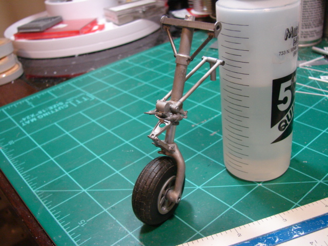
The NLG was one of the most enjoyable parts of this very large project; not sure why. Probably just the relief of getting through the shimmy damper!
At this time, all three LG were free to pogo up and down with only air pressure resisting. It was time to set the oleo extension and bond them down. So to do this I had to temp install the gear to the airplane, and fiddle with the extensions until I had them how I want (tail slightly tipped down):
And then I declared victory on the landing gear. The next tiger was going to be the nose gear bay. I will start with that on Part 3 coming soon. Please stay tuned and thank you for looking in!
© Jay Wheaton 2016
This article was published on Saturday, July 23 2016; Last modified on Saturday, July 23 2016