
21st Century Toys P-38J-15-LO “Lucky Lady” in 1/18 Scale – Part 1
By Jay Wheaton

About five or six years ago I rebuilt a 21st Century Toys (21CT) P-51 Mustang, named “Miss Velma”. (add link?). That project took about two years to complete, and several thousand hours of work. Although the Miss Velma effort was tremendously fulfilling, when completed I just about swore off modeling, it was that draining. But it also showed how what is essentially a toy can be transformed into a quite convincing large scale model.
Then in early 2014 while visiting my local hobby shop, I saw they had acquired a large collection of 1/18 scale 21CT models from an estate sale, and was selling them on the cheap. So in a fit of insanity I purchased a P-38, P-47, and an F4U, figuring when I retire, I might be looking for something to do. Well I didn’t wait to retire before jumping into the P-38 with both feet. I promised myself to keep the effort more low key and less extensive than Miss Velma. And it actually is in some respects (not in others). And it took me two and a half years to complete anyway, and was just about as draining.
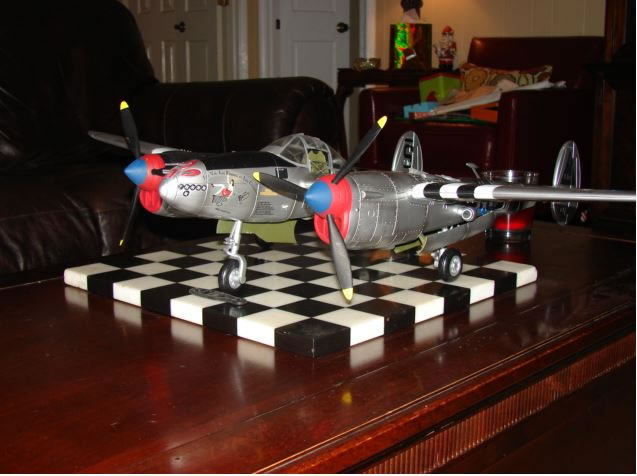
What strikes you immediately when you see the fully assembled toy is its size. To this day I have not figured out what to do with it permanently. Its wing span is just short of three feet, and its length is just over two feet. It literally covers my entire modeling table. Also what strikes you is the amount of work required to get it up to snuff looking like a P-38. The overall shape is adequate but that’s about it. However that is what I look for – a good base in which to work. Here is a “before” shot:
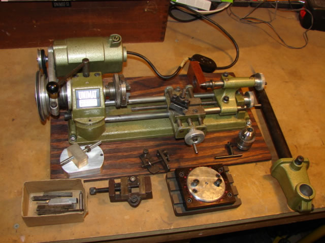
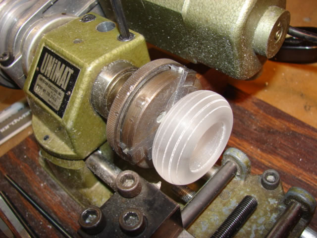
In support of this rebuild, I purchased a rather impressive two-sheet scale drawing of a P-38L in CD format, which has a great amount of detail and which served as my primary means of improving accuracy. That plus extensive CAD modeling enabled me to design accurate new parts where needed. Parts catalogues and the erection and maintenance manual helped as well. And importantly, I put out the big bucks for a mini-lathe and some accessories. Some master modelers use this or similar small machining equipment to make parts. For me – its primary job was to fabricate tires and wheels, although it ended up doing much more. Take a look:
I went on line and purchased some clear acrylic round bar in which to do the tires and things, in several diameters (max 2.0 inches). P-38 main LG tires are 36 inch outer diameter, or 2.00 inches in 1/18 scale. So I was off to the races with the tires.
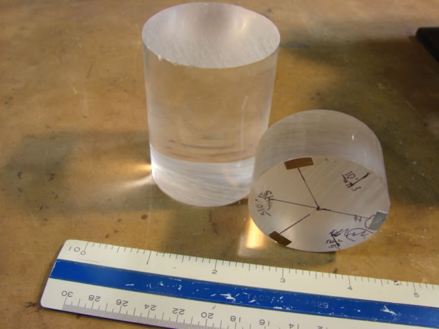
Actually, since this was my first time machining anything, I did a test piece in wood, and then after gaining some experience and confidence I began on the (much more expensive) acrylic.
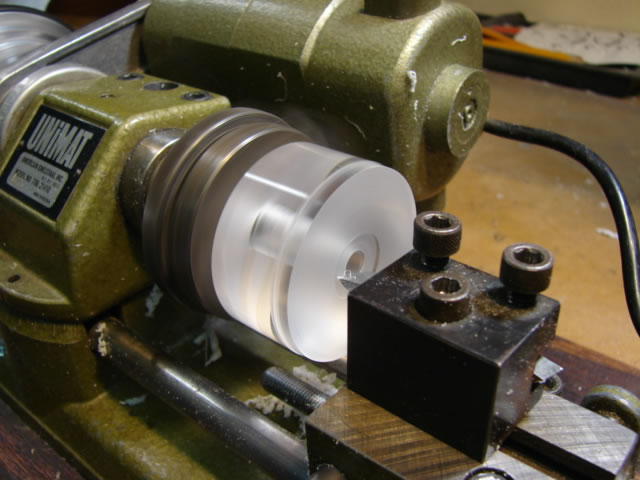
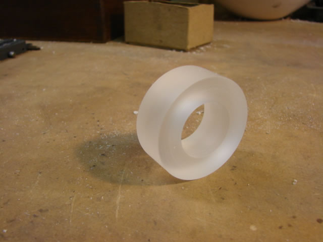
After some more turning, the main gear tire looked like this:
And finally like this (all three tires):
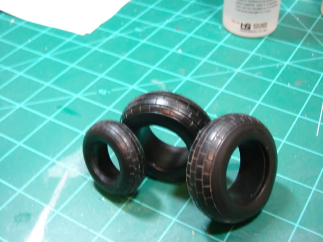
The block tread was really tough, because I had to manually cut the lateral grooves, and acrylic is very hard and durable. The tires also were cut flat and rounded with putty for the weighted look.
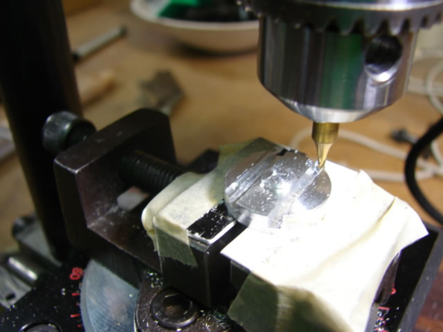
Wheels were more involved and required more material removal, as well as using the min-lathe in end mill configuration:
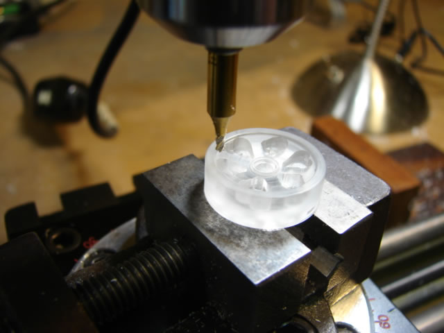
It was a bit nerve-rattling to make the holes which define the spokes, at that point I had a considerable time investment in the detail and did not want to ruin it with one small mistake. Here are some finished details waiting for assembly:
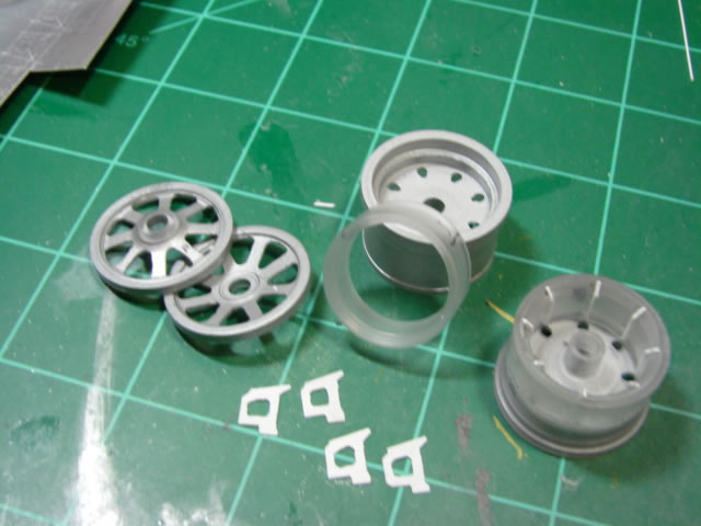
Note also I added in stiffening ribs, as I have come to understand that the actual wheels had them.
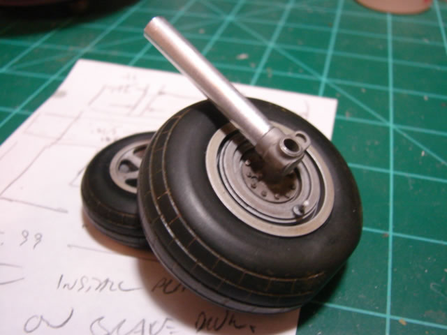
Here is a finished main tire and wheel assembly, and nose gear tire/wheel, along with some other turned parts (brake drums, axle caps, etc):
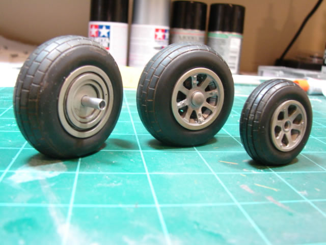
Those parts are a VAST improvement over the 21CT offerings. From there I would keep going upstream to the axles, lower strut, torque links, upper strut and beyond.
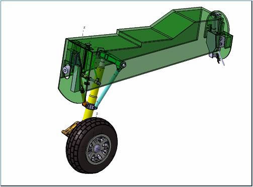
Here is an example of some CAD modelling I did (the main gear and gear bay). You will see those electronic parts come to life one by one.
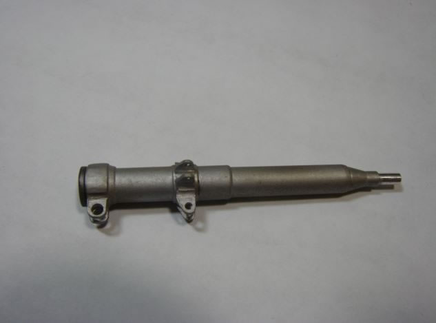
Here is a sequence for perhaps the most difficult detail part I machined – the lower strut elbow:
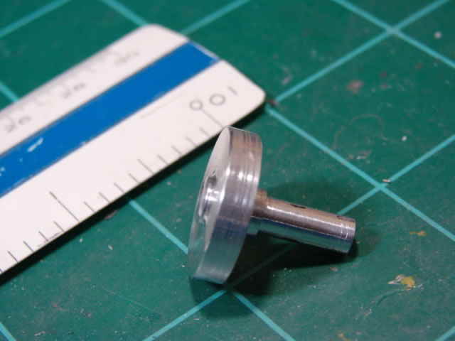
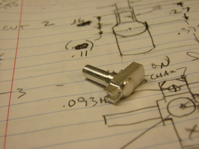

That was one of those parts which required hours of machine time, with the potential at any time to ruin it with a simple miscalculation or mis-measurement, or mis-cut. It was NOT very fun truth be told.
Let me give credit to Paul Budzik here. He has a marvelous website for his marvelous modelling, as well as a bunch of good how-to U-tube videos. Paul turned me on to the mini-lathe.
It was around now that I was breaking some of the more fragile acrylic parts, and it was recommended to me (duh!) to use a more robust material like brass or aluminum. So I added that to me growing collection of raw materials.
Here are some machined fittings and simple stock aluminum tubing which when assembled will be the main gear upper strut:
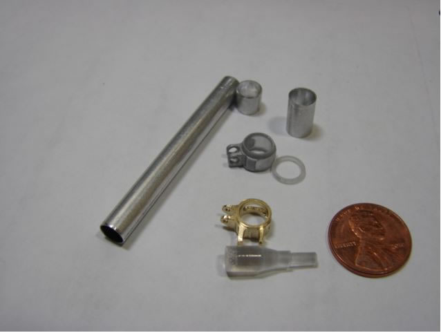
You can see that one of the fittings is made from brass. And the finished upper strut:
Some more machining work and other miscellaneous details:
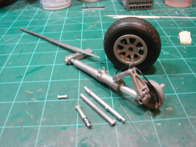
And here is a finished main landing gear assembly:
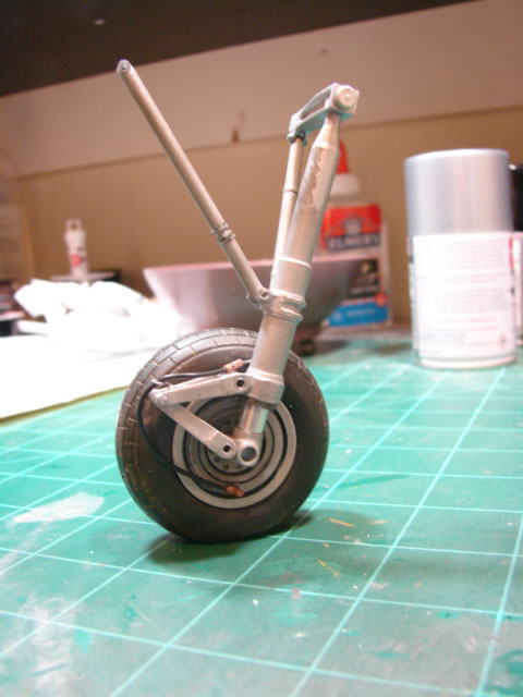
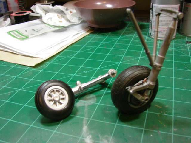
Just had to show a before and after! I will do that often as I continue with this story.
Next up would be the main gear bays. I will start with that in Part 2. Thanks for looking in!
© Jay Wheaton 2016
This article was published on Wednesday, July 06 2016; Last modified on Saturday, July 23 2016