
Building and Detailing the Revell 1/32 P-47 Razorback
By Chris Sherland
Preface
Having never built one of the old Revell 1/32 fighters, I chose the P-47 simply because it's my favorite WWII A/C, and I thought it would hold my attention through what I was guessing was going to be a long haul. I decided to go whole-hog on this project, and take the Revell kit as far as I could (which I procured from a fellow 1/32 madman here on the trader's board, Ronnie Murray). My plan was to add lots of custom features, and use as much after market stuff that could be rationalized with my wife. Jerry Rutman's detail set for the Revell P-47D Razorback was used, as well as the Teknics R-2800. More on these later. As it turned out I began to take a liking to scratchbuilding during this project (something I'd had no experience with prior to this build) and in a few instances I replaced not only kit parts, but some of the aftermarket stuff as well.
The Jug I started with showed decent molding and looked to be in great shape, this is a Revell-Germany issue, and was a 1988 release of the old '70s mold. This build was not hard, just long. It is my first detailing attempt and that shows! This is the ONLY big bolt out there to work with, until that is, JR bites the bullet and makes a resin offering for the whole dang thing!
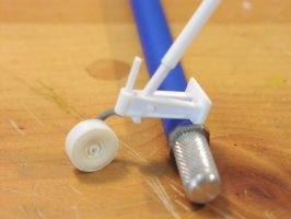
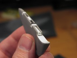
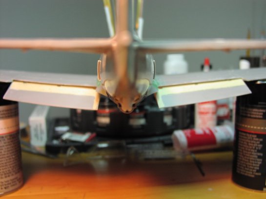
Why look how light the Thunderbolt must have been! Those scissor links aren't even breaking a sweat!
First Steps ... aka "Grab a saw boys!"
Revell's early practice of raised details and huge rivets suggested that the entire kit be sanded down for re-scribing first. I did, and went at it with lots of references. I used tape, a flexible ruler, a drafting template, the 1/48 Verlinden scribing template, an Xacto scribing needle, a punch wheel set, and a modified syringe needle for rivet detail. Later in the build in part II I will focus on scribing a bit more. Initially it was simply sand down and "sketch" the panel lines back in. I wanted to wait until wings, tail, and fuselage were mated prior to finalizing the re-scribe job.
I decided to articulate all of the flying surfaces, and the first step was cutting them all away. Soft plastic helped here, but ½ way through I realized what I had gotten myself into. The Jug employed fowler-like flaps, and weighted ailerons…lots more work than I had anticipated prior to letting the knife fly, but how does that saying go? "Oh well!" The engine exhaust vents on the lower sides of the fuselage just aft the cowl flaps, as well as the turbo supercharger exhausts on the fuselage sides are poorly represented in the Revell kit and had to be removed for replacement. Lets just say I spent a lot of my initial time with the kit sawing and stabbing.
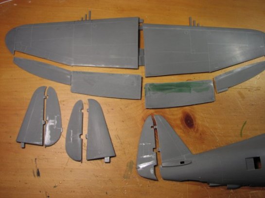
All surfaces cut away, had to ditch the kit flaps. Some early scribing can be seen here too as well as the turbo exhaust opened.
The Revell kit lacks a lot of detail in some places and passes quite well in others. The Jugs myriad of venting ports under the rear fuselage were not one of Revell's high points. I ground away at them until I got a "passable" scale feel. I didn't feel like going too much further to tell you the truth. The Dremel and a scribing needle did the job here.
Venting ports cut out of the fuselage, and more early scribing.
The most challenging part of this stage was opening the fuselage and wings for new scratchbuilt gear bays. The kit's bays are not accurate and need more than help if a detail job is planned, they need to be replaced. There is a lot of sawing and grinding to do to remove the kit's bays for replacement due to the fact that the Jug's gear bays slightly penetrate the fuselage as opposed to just residing within the wing structure like on a Spitfire or a 109.
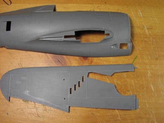
Fuselage and lower wing opened to accept gear bays. Note the cowling has been removed for the Rutman replacement. Both the turbo and engine exhaust flaps have been removed prior to adding the scratchbuilt ones.
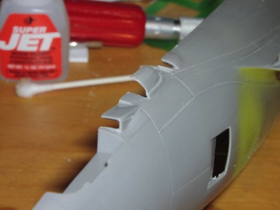
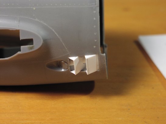
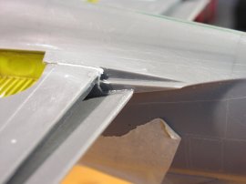
The articulated turbo exhaust flaps on the side of the fuselage were in dire need of some scale. The kit's flaps here were bulky and inaccurate. I cut them away and scribed a pair of channels into the top and bottom of the exhaust's backing which I left on. From there I built the flaps from .10 sheet and inserted their mounting walls into the channels. With this technique I could choose to mount them in ANY position desired.
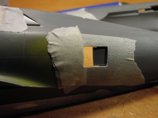
Channels cut in kit fuselage sides for the turbo exhaust flaps. These were done with a scriber. The longer you go with these the more mounting options you have, including fully open or fully closed.
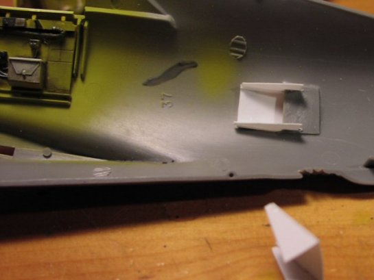
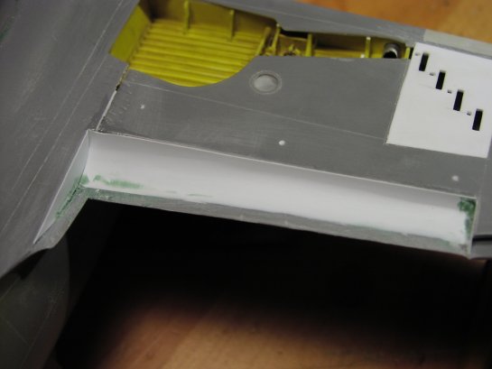
The turbo exhaust flaps getting fitted from the inside of the kit fuselage. .10 sheet was used to construct these. Note some cockpit detail as well.
Cockpit
Once all the basic prep was done, the next step was getting the Jerry Rutman cockpit together to set the stage for mating the fuselage halves. Although there is quite a bit of work involved, Jerry's cockpit set adds quite a bit, bringing real validity to the old Revell piece. There were gobs of fitting chores and choices to make in order to get it "right". I made a huge error early on in the cockpit assembly, which was cementing the cockpit walls to the kit fuselage sides instead of assembling the cockpit tub as a whole, then installing it into the fuselage (that'll teach me to skip the instructions!). There is an angle problem with the walls in this configuration, but it still came out fine. I scratch built the fuselage canopy rails and used the rudder pedals from the Revell kit. Seat harnesses were made from masking tape and the photo-etched buckles that come with the Rutman set.
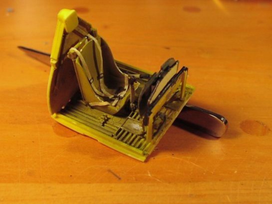
Cockpit tub prior to final detail, and mounting.
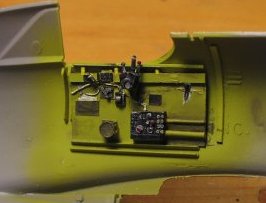
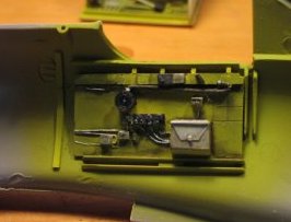
Side panels almost finished. Note horrible scar on the left, this was needed to get the panel to sit right.
Jerry Rutman did a great job on the resin throttle quadrant, including prop and mixture levers. I chose them over the photo-etch versions that are included as well, and only needed to scratch the prop and mixture handles from small rod and some glue "knobs". Not much more detailing on top of the resin cockpit, a few photo-etched panels, and the throttle control tubes were all that would be seen once the tub was installed, so I played it cool on detailing stuff that would be out of sight.
For the main panel I decided to combine the photo-etch gauges and panel supplied with the Rutman detail set with a clear sheet insert to simulate the dial glass. The photo-etch panel is finished a bit on the gaudy-side, so I sprayed it flat black to tone it down a tad and give it a more subdued look. The clear sheet was measured, cut, and cemented to the etched gauge panel, and then the etched front panel was cemented over that.
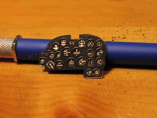
Finished instrument panel.
Tail Gear
Prior to mating the fuselage together, the tail gear and bays must be tended to, and prepped.
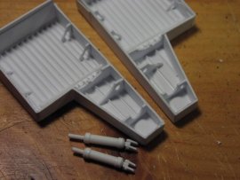
Republic didn't skimp on complexity when they made the tail gear assembly for the P-47. And I firmly believe this is why every Jug kit you see has that goofy canvas "bag" draped over the whole thing, showing only the stem and wheel. Well I'm here to tell you that I've never seen any photo of a single combat Jug with that crazy bag on!! Needless to say the tail gear supplied in both the kit and the Rutman set avoid the Jug's tail gear system details in trade for either the canvas "boot", or an oversimplified flat deck that the gear strut just sticks into. Neither was to my liking so I sawed out the flat gear bay decking, and scratchbuilt the tailgear using the Rutman wheel, the kit's wheel arm, and all the rest fashioned from sheet and rod. The P-47's tailgear has a very distinctive yoke, and again, it seemed to be a prime candidate for some scratch-building. Thick styrene card was used to fabricate the yoke arms while styrene rod and tubing were used to do most of the rest. Some more sheet was cut and shaped for the mounting panel and interior bulkheads. Small strips of sheet were added to the interior walls to give some body to the bay.
The tail gear assembly ready to mount and the bay prior to final detail.
Moving On
Once the cockpit, tail gear and turbo flaps were installed, the fuselage halves were joined with standard CY. At this stage some of the final fuselage scribing, filling, and sanding was tended to, as well as building and installing the scratched exhaust flaps near the cowling. A note here on the exhaust flaps. I have sniffed around some surviving Jugs and these flaps loosely hide some of the main exhaust piping. I added these pipes in because they are clearly visible on "real" Jugs. This is all simple sheet and rod.
Fuselage halves together, and the mounting of the scratch exhaust flaps, Rutman firewall, and Teknics R-2800 followed shortly.
Engine
The Teknics R-2800 went together well, although it only arrived with 16 cylinders! Now I know that a real Jug could have made it home on just 16, but "hey c'mon, I'm building a model here!"
Replacement cylinders were sent to me, and all was well. I spent some time detailing the front of the engine, and the exhaust (it would be visible through the open cowl flaps) but did not dally here too long, I hate working hard on stuff that can't be seen. Small rod stock was used for the push rods, cut to size, and then cemented in place. Guitar string fastened with epoxy was left to set and then bent to shape representing the wiring on the face of the R-2800.
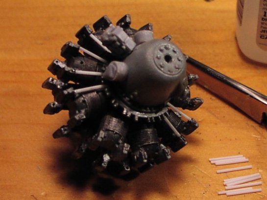
The R2800 getting pushrods installed
After the engine was done I fixed it to the firewall (Rutman resin piece) along with the modified "bell" mount from the kit. Lots of sanding and fitting were needed both prior to attaching the firewall as well as afterwards to attain scale and shape. Not much of this is visible in the finished kit, so again, not much pain spent.
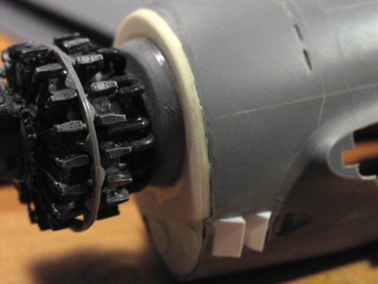
Still a little filling/shaping left to do.
Tail
With the tail feathers cut away I filled and shaped the control surfaces and rebuilt all the hinges from stock. A note here; these are not attempts to make real hinges, just a stab at getting a better feel than the kit monstrosities.
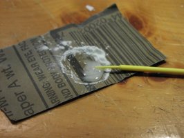
Using a trick I learned from responses to a page question I posted I mixed some "goop" from 1/2 talcum powder 1/2 slow CA. This dries a lot softer than straight CA and is easy to control with ratios and then can be cured fast with accelerator when needed. This goop was used as filler to flesh out the airfoils on the elevators. It's a great tip and I'll be using it everywhere I need good strong filler and some control over the hardness. The rudder was filled and "spaced" with stock and rod segments, then capped with sheet and shaped with Milliput.
In all these photos you can see where the original kit hinge spaces were filled with various thicknesses of sheet to get some decent scale. I eyeballed the sizes here, no need for going insane, I was just looking for some scale.
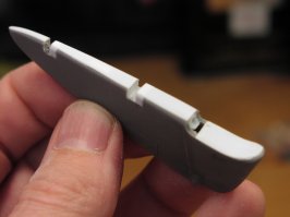
The rudder with spacers, and then capped prior to Milliput shaping.
Hinges added, and the most-excellent "goop".
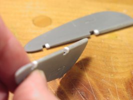
Elevators with reduced hinge spaces, capped and shaped with goop.
Main Landing Gear and Bays
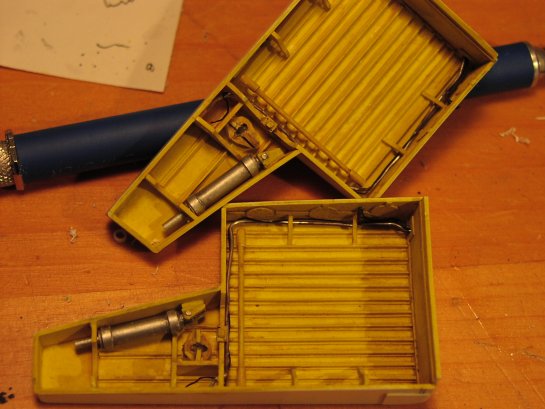
After getting the fuselage together, the gear bays needed to be dealt with next and I decided to scratch them. I had purchased a set of bays from Jerry Rutman however they were not quite accurate. I used them as a guide to build a set from scratch. There are 2 major issues with the Rutman bays, one is that the bay floors lack proper ribbing and alignment, and the second is that the main hydraulic piston mounts are on the wrong side of the bay. Nit picking some would say, and rightly so. But I was possessed by this time.
Having been inspired by John Formon's scratched bays on his P-47 D-25 I set out to make my own. This was not a huge chore, but taking my time made all the difference here. There are a lot of considerations to take into account as you build these and going slow helps reduce re-dos and big mistakes.
Once I got the basic floors and walls together I ran through some fitting and shaping. Once the fit of the basic structure was sound I detailed and painted them. Wiring was made from various gauges of thin wire and soft aluminum rod.
Sketched-in bays getting test fitted on the left, and final structural detail on the right.
All that's left are the gear door actuators and MLG fitting.
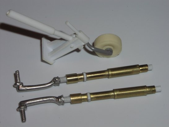
The MLG from both the kit and the Rutman set were not to my liking. So I set out to scratch them as well. Having never built a set of MLGs before I sought lots of help from LSP folk. Scott Murphy, John Forman, and Armand Eshleman all offered invaluable assistance. Thank you gents!
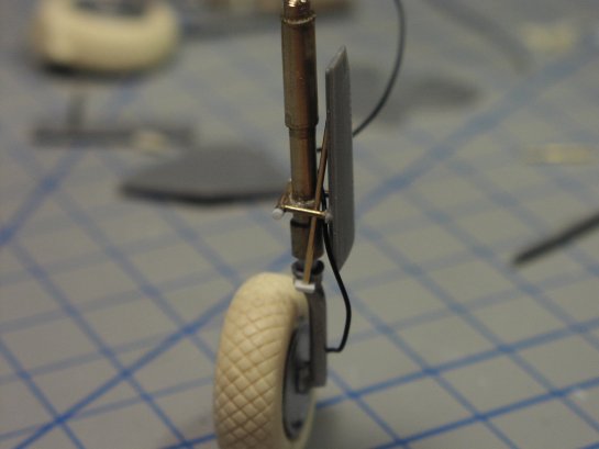
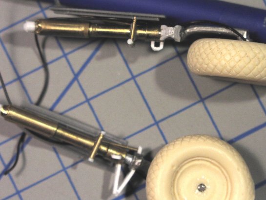
Here are the main struts and a detail of the tail gear all sketched in prior to detailing. The MLG struts are brass tubing, styrene rod, and the white metal wheel arms from the Rutman detail set. The styrene rod can be seen as the oleo here. Careful drilling into the white metal wheel arms to accommodate the styrene oleos was the highlight of assembly.
Fin Correction
One of the tasks that I was dreading was the fin correction for this kit. The fin and rudder are both misshapen (long known flaws in the Revell T-bolt), and require some heavy attention. Until I saw the discrepancy I was on the fence about doing the correction at all, but once I did see it, it bugged me so bad that I finally relented. Scott Murphy emailed me a great guide for the correction. I have no idea of its origin, but looking at my references it's right on.
The correction is not hard to do. I used Milliput and I believe that this is the best route to take. After a bit of scarring and scratching was done to prep the leading and trailing edge of the fin and rudder, Milliput was rolled into long strings and applied along the prepped edges (see drawing below). Pressing and molding the string of Milliput to the edges it was worked with water and fingers until there was no bulging seam or drastic changes where the kit fin surface and Milliput met. Water helped here a LOT. I was able to smooth the Milliput out enough that initial filing was minimal.
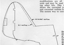
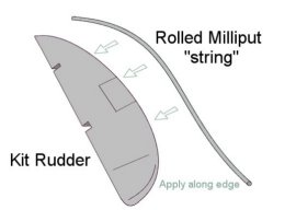
The JPEG Scott Murphy sent me and how I applied the Milliput initially (rudder shown).
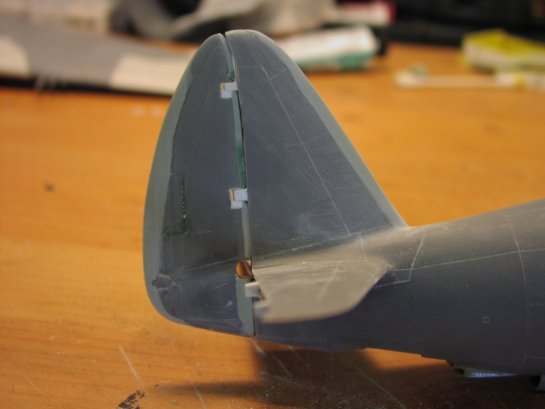
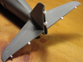
The fin and rudder corrected and awaiting final detail and mounting.
Wings
The wings were by far the most abused parts in this build, from the initial sawing off of the surfaces, to the grinding out of the bays, and finally the replacement of the guns, there wasn't much left of 'em, but they held up OK. Assembly was a bit tricky as the gear bays require a bit of deep penetration into the fuselage, prefitting and sanding were the call of the day(s). John Formon supplied yet another great tip on wing strengthening, and by golly by this time they NEEDED it!
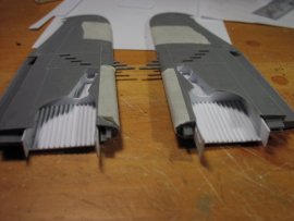
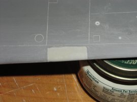
Landing and signal lights were done before the wing halves were mated, as were the shell and link ejection chute panels.
The lights were a lot of fun to do. MV products were used (Model Railroad Accessories) and fit the bill nicely. Proper holes were drilled and finished, then "dished" from behind with the Dremel to accommodate the convex lenses. The lenses were placed from the back, then CA was beaded around the edges and accelerated with Zip Kicker. All told the desired effect was achieved.
Holes drilled and finished.
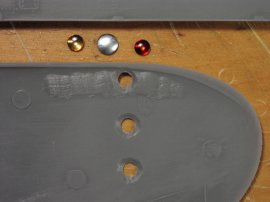
Beveled from the back, holes are ready for the lenses.
CA beaded around the seams and kicked.
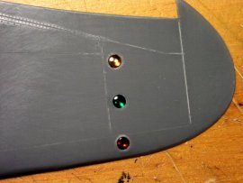
Final product from the "good side".
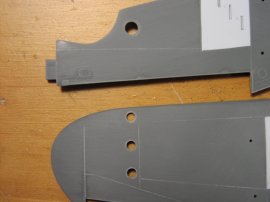
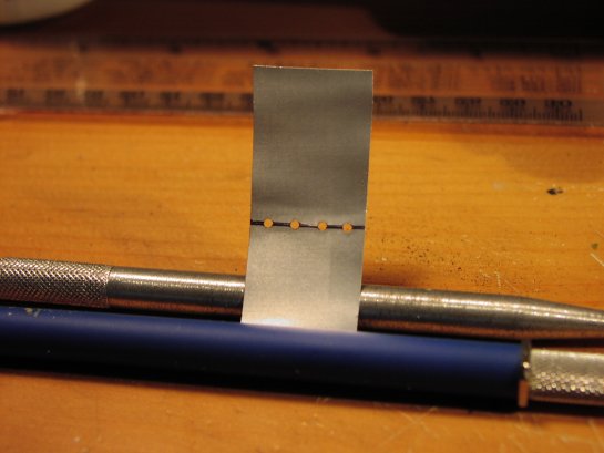
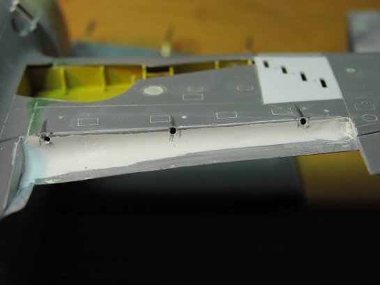
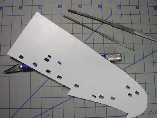
The shell ejector holes on the Revell kit are too big, and the link ejector holes do not exist. The entire panel was removed and a new panel was measured, fabricated from .020 sheet and installed. The holes were measured off and outlined into the new panels with a scriber. Then they were drilled out with a pin vise, squared off with an Xacto knife, and finally trued with a small jeweler's file.
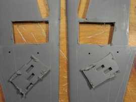
Kit panels ditched.
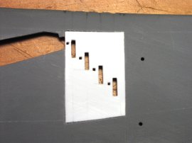
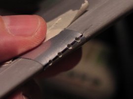
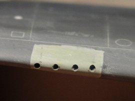
New panels mounted and holes done.
Merging the wing halves was a pretty sketchy job, they had been so mangled by this time that there was not much hope of getting them true without a plan for additional support. Holes were drilled through the merged wings, styrene rods were inserted and their ends snipped and sanded flush.
The gun barrels on the '47 are set up parallel to the ground, but the kit's guns are aligned along the leading edge of the wing. I removed the gun-section of the leading edge entirely, filled it with Milliput and shaped it with the Dremel and hand sanding.
Leading edge removed.
Filled and ready for new holes. I knew those empty baby food jars would come in handy!
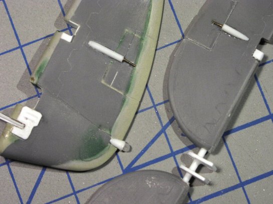
New holes were drilled with the correct alignment and prepped for replacement barrels made from aluminum tubing.
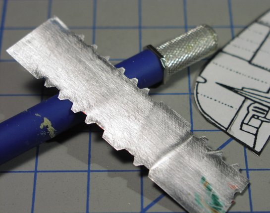
I made a template out of soda can aluminum and taped it over the leading edge of the wing to get accurate spacing and orientation. With the template in place I used a pin vise to drill the holes. The template helps not only insure proper alignment, but assists in steadying the pin vise and keeping the holes true.
The gun alignment template made from a soda can.
Template taped over edge and new holes started.
Final holes ready for aluminum tubing "point fifties"!
At this point I mounted the wings on. What a shock to see the size of this beast. It was all together livable when it was a heap of parts, but mating the wings set a new tone for the build and got me pumped.
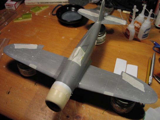
"Honey?...I think we're gonna need a bigger house!" ...the T-bolt begins to take real shape.
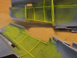
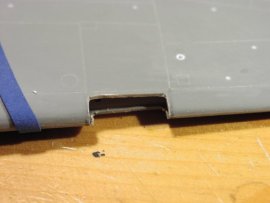
There was no avoiding the flap bays at this point. I began by prepping the bays to allow for accurate final construction of the flaps themselves. First the sides were addressed by grinding and shaping, then I fabricated the bay walls with thin sheet and some tricky "bending".
Inboard flap bay wall needed clearing out and reshaping.
Flap bay installed and ready for final detail. Note the gear bays from last installment getting beaten into submission.
I then puttied the wing roots and prepped them for final sanding and detail. The kit wings fit fairly well even after all the abuse, and there was not much trouble here.
The Rutman Cowling
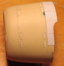
The P-47 cowling offered by Jerry Rutman provides the correct outline and shape where the kit cowling falls short. I was very pleased with this piece from JR, it's very well cast and requires only a minimal amount of shaping to bring it some better scale. I thinned the walls a bit, reshaped the cowling lip a bit, and had to do some minor modifications to mount the cooling flaps. I used the kit's "chin" piece slightly modified. A bit of internal ribbing was added as it would be visible through the opening, simple thin sheet here, nothing fancy.
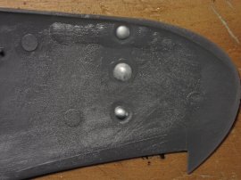
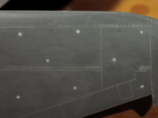
Dsus fasteners are not represented on the Rutman cowling, and being highly used on a combat aircraft I decided to model them. John Formon slipped me a great tip on these and I took his advice. I scribed the fasteners out of .005 sheet and glued them onto the cowling. Then I scribed their outline and sanded them down to "almost flush". This gives them a bit more relief than a simple scribing job, and allows for a better look.
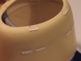
The Dsus fasteners glued in place prior to scribing and sanding down. Note some internal ribbing to flesh out the cowl interior and the kit chin piece.
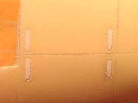
Dsus fasteners scribed and sanded down "almost flush".
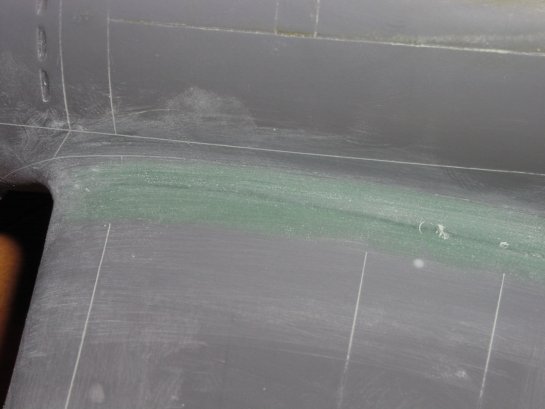
I decided to model the cowl flaps in the closed position, and the resin cowling had to be modified in a few areas to make all the measurements come out right. The center cooling flap seam on each side lines up with a long horizontal fuselage panel line that runs all the way back to the tail. Getting those to match up just right required ditching the template that is included in the Rutman set and fashioning my own flaps. Some simple bracing on the inside of the cowling was added, then the flaps themselves, then additional bracing on the backside of the flaps to "true" them to each other.
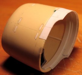
These shots show the flaps and bracing inside the cowling. Gotta measure these carefully and check your references to match any panel lines on the fuselage.
Final Construction
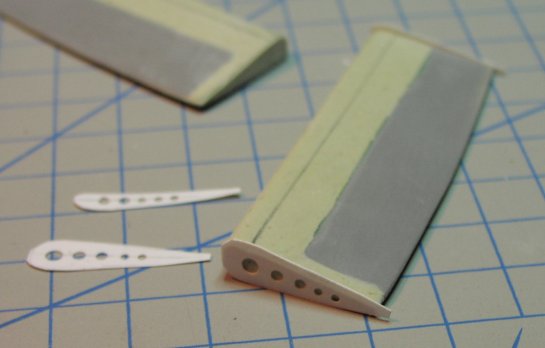
Flaps
The Jug's fowler type flaps represent a decent challenge. They are by no means easy, but they are not impossible. Planning and more planning before construction and mounting is essential to getting a good result.
I had elected early on to ditch the kit flaps and fabricate my own. I later rescinded this call, and salvaged the kit flaps after all. I would HIGHLY recommend using the kit flaps as they retain valid basic shape and need only fill and finishing. When you remove them however, the bottom portion has a wider chord than the top, this is due to the way fowler style flaps mount and function.
You can see early mounting holes drilled to accept the flap actuators explained below.
Milliput was used to flesh out the flaps' top and leading edge, as well as the inboard section that is covered by the wing root when the flaps are up. Here you can see the side facades being added. These are not "accurate" in as much as the lightening holes are misrepresented, but they give a good feel.
I used a hand drill and some Jeweler's files to create the actuator bays. Again I must sing the praises of Milliput...it just never fails as a filler. Here are the actuator bays from the top and underside.
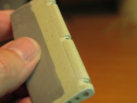
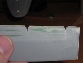
For mounting I used small brass "I" beams bent into shape and then epoxied into the actuator bays. The brass goes about 1/2' into the flap for added stability. I then mirrored the mounting holes in the flap bays themselves for the other end of the brass beams to mount into.
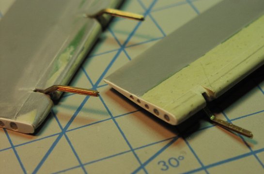
Here are a couple of shots of the flaps test mounted. The plan is to paint them separately and then mount them for decaling weathering and sealer.
Landing Gear
The gear was made from brass and styrene rod and sheet. Nothing too special here, lots of measuring and test fitting. Rutman wheels and the kit doors are the only components not scratch built.
The scissor links were a pain in the a$$! I used sheet styrene and cut a template, but they were small and hard to work with. I'll be looking for a better way next time.
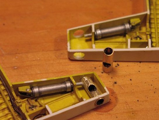
Prior to mounting inside the wings, the gear bays were fitted with a mounting cylinder for the MLG. I made these out of brass and epoxied them into place. The MLG shaft tips will be epoxied into these cylinders after basic painting tasks are complete.
Scribing Finals
I made a couple of custom scribing templates out of soda can and sheet styrene. The Jug has a LOT of access panels on the underside of the wings, and getting them consistent from wing to wing would need a template. I photocopied some scale drawings up to 1/32 and traced the panels onto the sheet. Then with a trusty #11 and some jewelers files I cut and trued the template guides.
The same thing was needed for the geometric lap joints on the tail feathers of the P-47. These are very distinct and I wanted them to be consistent as well. Soda can aluminum was used again, and the same drawings were enlarged and used to trace the pattern onto the aluminum sheet. One side is the elevator pattern, and the other is the pattern for the rudder. Simply flipping these templates over on their backs allows for both sides of the aircraft to get the same consistent scribing patterns.
The rudder and elevators were finalized and detailed with the scribing template and some sheet styrene.
Of note are the actuators for the elevators and all trim tabs. Mostly sheet styrene and brass rod. The light on the rudder tip was made with scrap clear rod and styrene tubing. Shaped with a Dremel then polished.
Details
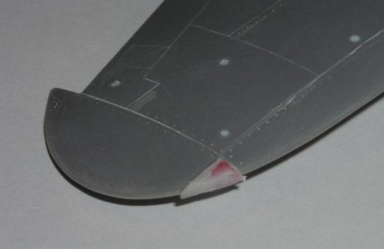
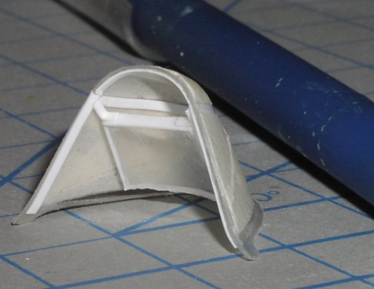
The wing tip lights were made out of clear shower curtain rings. I cut a basic pattern out, then made a "groove" light bulb, painted it and mounted the lens. From there it was just some shaping with the Dremel and files, then they got a final polish when the Jug was paint prepped.
I must admit to seeing this used on a number of other models, and also in a few tips book. It's not big news, but it works well!
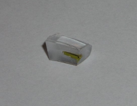
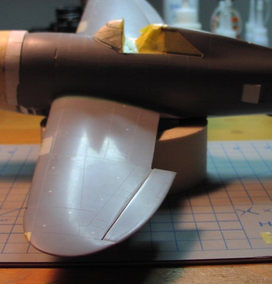
The windscreen on the Razorback Thunderbolts was very unique. With a center brace the gunsight was offset, and the armored glass was applied inside the windscreen and mounted directly in front of the pilot's head position.
Clearly the kit canopy had to go, it is misshapen and as thick a a 2 X 4 in scale. Brian Cauchi sent me some vacs of the kit canopy and while they were much better scale wise, they still did not have the correct outline and shape. Squadron carries a replacement vac that is much more accurate and I procured one of them. It is a great vac piece and makes a lot of difference in the canopy and windscreen profile.
I used sheet styrene to both make the framework and the brace for the armored glass. The armor glass piece is just thick clear plastic cut and shaped.
Painting Prep
I completed the Rutman gunsight (from the update set) and fashioned a glare shield from thin brass rod and masking tape. Once these were in place I painted the interior of the windscreen and armor glass and mounted the windscreen.
I sanded the whole kit down with 600, then again with 800, and finally with 1K. I then went back looking for trouble spots and scratches, found em, and repeated the above in localized areas.
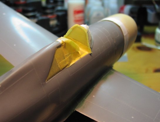
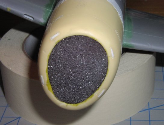
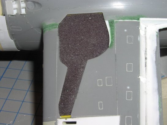
Once I was satisfied with the sanding I masked off the cockpit and wing lights with masking tape. The flap bays and cowling were masked using foam cut a little bigger than needed and "stuffed" into the openings.
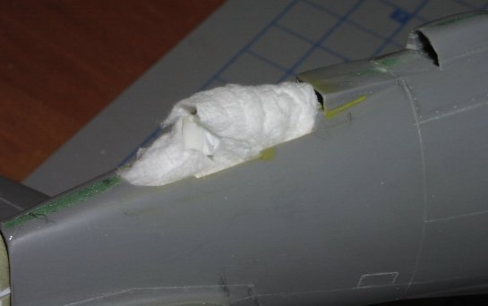
Good old tissue was used for the tail gear bay masking.
In Closing
At this point it's all about painting and weathering. You won't see an update on this old beast until I put a final sealer on it...you're probably pretty happy about that by now!
I hope these pages will be of some help to anyone wishing to work the Revell Thunderbolt over. It's not an easy job, but it's not extraordinary either. It's all about patience and creative thinking when you get into a bind. I re did at least a third of the scratched stuff when my first attempt failed or was measured incorrectly, and always bowed to patience when I got stuck.
These Revell kits are worth the effort. The best thing about them is that they stand as decent out-of-box efforts, but they also form a great canvas for taking them as far as you want to.
Please see the finished build article for a summary of the build and final photos.
References
- Mustang and Thunderbolt Aces of the Pacific and CBI (Osprey) ISBN 1-85532-780-5
- America's Hundred Thousand (Dean) ISBN 0-76430072-5 (This is simply a MUST HAVE for USAAF and USN WWII fighter reference!)
- Aero Detail #14: Republic P-47 Thunderbolt ISBN 4-499-22648-1
- Warbird Tech #23: Republic P-47 Thunderbolt ISBN 1-58007-018-3
- Squadron/Signal Walk Around #11: P-47 Thunderbolt (Drendel) ISBN 0-89747-375-2
- Squadron/Signal In Action #67: P-47 Thunderbolt (Davis) ISBN0-89747-161-X
- Warbird History: P47 Thunderbolt (Hess) ISBN 0-87938-899-4
- Pilot's Manual for P-47 Thunderbolt ISBN 0-87994-026-0
© Chris Sherland 2004
This article was published on Thursday, October 22 2015; Last modified on Wednesday, March 09 2016