
Williams Brothers 1/8 Wright J-5 "Whirlwind" Engine - Part 2
By Rogerio "Rato" Marczak
After looking at all those small details I realized this wouldn´t be a quick project, as I initially thought. In particular, photos of aircraft engines show dozens of bare metal nuts and bolts. Although some of them are painted over at factory after assembling each subsystem, it takes just a couple of maintenance disassembling to pell off the paint on them. That is, I had to tackle all those nuts and bolts, and it would be a very boring hand painting task.
Trying to make things a bit faster, I advised a masking method to paint those countless bolts. A strip of Tamiya masking tape was laid on a length of double side adhesive tape backing paper. Then, an array of circles was punched out using the venerable Waldron Punch & Die set. The diameter of the holes was slightly smaller than the nuts/bolts I wanted to paint. The tape was then cut in small pieces containing a hole in the center, and they were pressed around each nut. In order to test the method, I elected the cylinder bases for a try out.
Next, a took Model Master Steel enamel (#1780) and applied a sort of not-so-dry-brushing around each nut. The tape allows you to use a larger brush and be a bit messy, speeding up the process in comparison to brushing them with a fine point brush without masking.
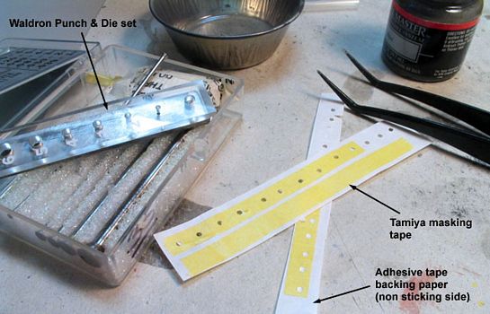
Preparing the masks for the cylinder bases nuts.
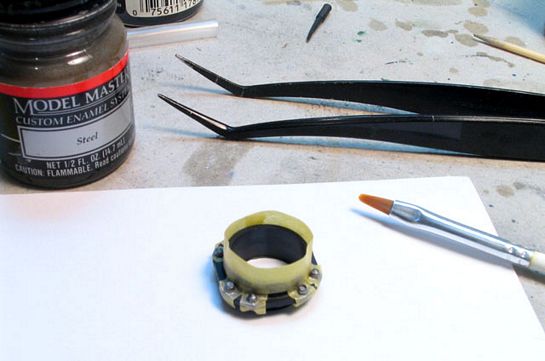
The nut masking in action.
It works? Yes, it works. However, the MM enamel doesn´t have the coverage I was expecting (maybe a consequence of not priming the parts), and I´m still not fully satisfied. On the other hand, the MM Steel provides a quite decent representation of (guess what) actual steel color. Looking at each nut individually, they don´t seem good enough, but the overall effect is passable. They do seem even better once the cylinder bases are attached to the crankcase.
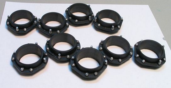
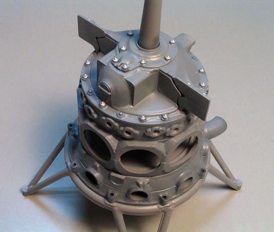
All the cylinder bases finished.
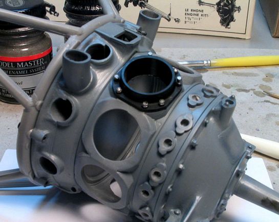
How it looks after installing.
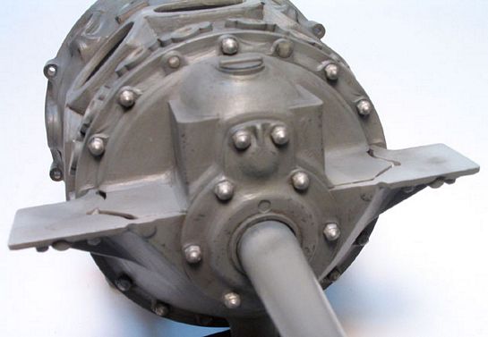
I must confess that the time consumed preparing/applying the masks is roughly the same of painting each nut without the aid of masking. So I finished all the cylinder bases this way and dropped the method for all other nuts and bolts. This time I used Tamiya XF-16 Flat Aluminum enamel, wich provides a much better coverage. Strictly speaking, the color is not correct, but I antecipated that after a good brown/black wash to tone the bright down they would look closer to steel. All the nuts around the reduction case were painted without masking using a 000 brush, as well as the front shaft bearing flange and the magnetos attachment joints. All the remaining nuts and bolts around the accessory (rear) area were painted this way, too. The pictures below show the result.
The crankcase bolts freshly painted and...
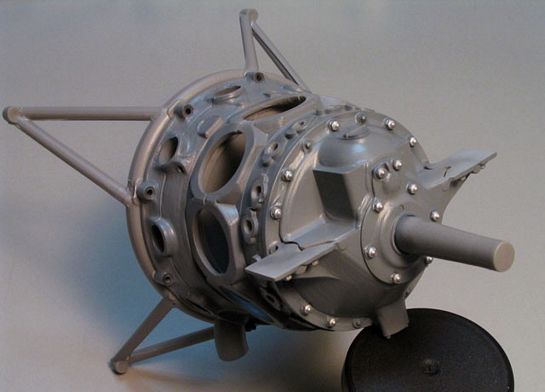
...another view.
At this time I finally decided for discarding the rubber parts provided in the kit in favor of new scratchbuilt items. I made a resin copy of the exhaust pipes to be used later as the air heating exhaust. New carburator air heating intakes will be scratchbuild later, once the accessory area is cemented in place, allowing me to make correct measurements.
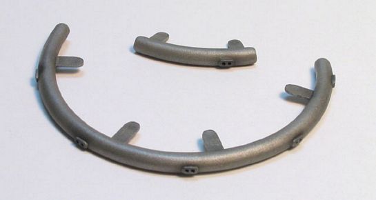
As for the ignition harness loom, a new one started its life as a length of sprue. I sank it in boiling water for some minutes and rolled it while still maleable around a tin of proper diameter. After it cooled down, I cut the distribution arcs using the kit rubber parts as a guide. The real part has small elliptic protuberances from where ignition wires come out to the spark plugs. I made them with small rectangular pieces of plastic card rounded on the corners. After the glue has set, I drilled the holes to accept the ignition wires later. The last step was to make the six anchoring plates which hold the ring in place around the reduction case.
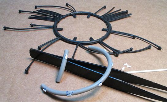
The ignition harness loom in its ealy building stage.
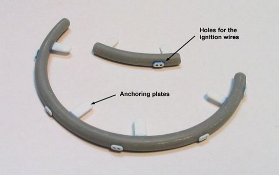
Anchoring plates added and the wire holes drilled.
I made resin copies of the mounting studs molded on the rubber ring. They will be added to the anchoring plates later. The parts were primed, and then airbrushed with MM Steel. Next, a coat of Gunze flat clear acrylic was applied to reduce the shine and replicate that oxidized look. The last step was to shot very thinned Gunze soot (H-343) on some spots to simulate grimy areas. It really looks better than the rubber one provided in the kit. However, I kept that one intact to be used afterwards as a template for the ignition wires.
he ignition harness loom finished (missing only the mounting studs).
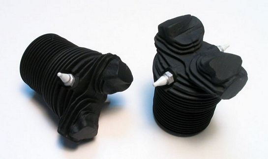
The cylinders had the hexagonal bases of the spark plugs painted in the same way of the nuts. To simulate the porcelain (conical) part of them, I firstly brushed Gunze Flat White (H-11). Once dry, a generous coat of Future Floor Wax was painted over the white area to produce a glossy finish.
The cylinders with the spark plugs painted.
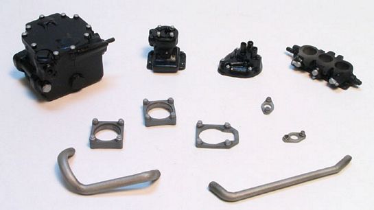
At this stage, major subsystems of the accessory area (fuel pump, oil pump, carburator etc.) and smaller parts were painted with black, engine gray or steel, always highlighting the most prominent details with Aluminum (toned down afterwards with a brown/black wash). I applied Gunze flat clear on some areas of the black painted parts for a better effect. The steel parts received a bit of Gunze soot, just like the distribution ring described above.
More boring detail painting.
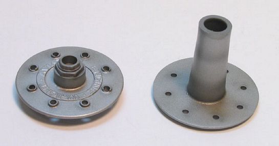
The carburator air heater also received the MM Steel / Gunze flat clear / wash treatment. The propeller hub and drive flange were painted with Floquil Old Silver (F110100), and they were toned down with flat clear too. I simulated some artificial shadows and soot using Gunze Soot. The center hexagonal nut of the propeller drive flange will receive a heavy wash later (hope I won´t forget).
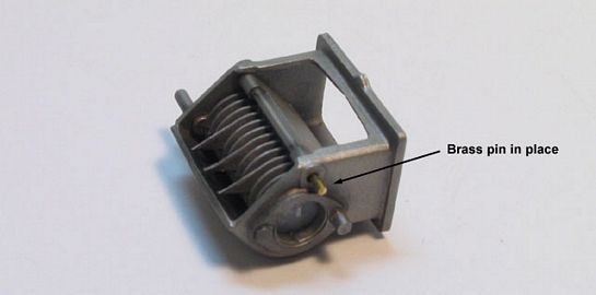
The bypass valve was modified to enable its assembly later.
The bypass valve was modified to enable its assembly later.
The most disappointing parts of the kit are the short/long nuts/studs. They all suffer from severe mold shifting, and lack the proper cylindrical shape. The sprue gates where they were attached are about the same size of them, making the parts removal a real core. I won´t even mention the formidable work necessary to clean these tiny parts - one by one. Of course I had the option of correcting one of each to cast resin copies, but what the heck, I´ll live with them. I painted and washed them crossing my fingers that they won´t look so bad after installed.
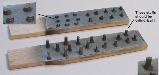
A difficult step: cleaning and sanding all these bits.
Next, I proceeded with an overall wash on the major parts. The wash superimposed to the pre-shading (see Part 1) resulted in a darker grey color, but it is still nice. I used a large flat brush and oil paints diluted with mineral spirits for this major wash. Incidentally, it flattened significantly the gloss gray previously applied, and I decided not to apply a semi-flat clear overcoat.
Some paint chipping was accomplished next, mainly around the front area of the engine, which receive most of the ground debris. I understand that the impact of tools during maintenance also takes its toll. I didn´t use steel or aluminum colors. What I wanted is that oxidized paint chipping - almost black. So, instead, a 4B pencil was randomly scratched, concentrating the effect on high curvature areas, edges, and protuberances. As you all know, it is quite difficult to keep it realistic. I´m still learning here, but I´m satisfied with the final result...
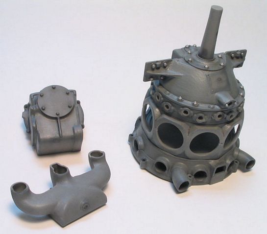
The major parts after receiving a first wash.
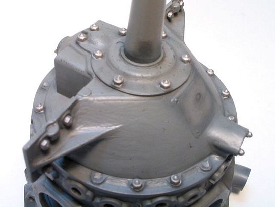
A close look on the chipped paint effect.
Another look on the chipped paint effect.
The engine mount also presented very heavy mold shifting marks. I spent a couple of hours to remove them completely and sand to an acceptable finish. Since the mount will be used to actually display the engine, I painted it with Gunze Cream Yellow (H-14) acrylic, washed it, and simulated a heavy paint chipping in the same way I did for the engine.
The kit doesn´t bring any sort of fixture device to install the engine on the mount. The instructions call for 00-90 brass screws and nuts (available from model railroad shops) to secure the engine in place. No way I´ll find it around here. I need an alternative...
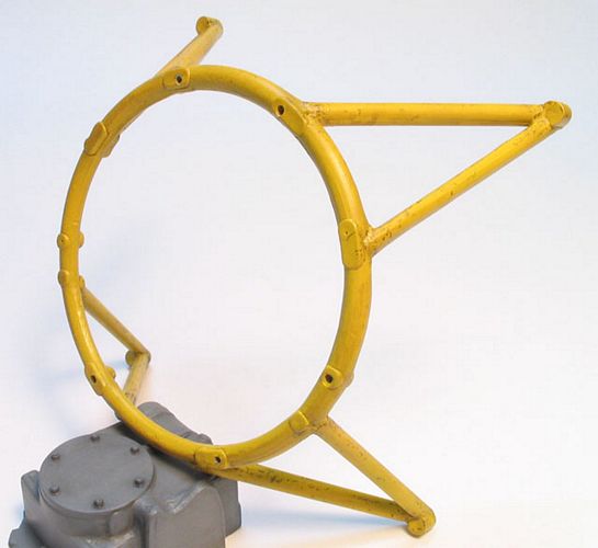
The engine mount painted and weathered.
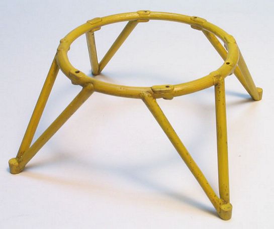
The engine mount painted and weathered.
There are still a good number of smaller parts to be painted before proceeding to the final assembly. Since the instructions are very generic in color calls, I will use a bit of artistic licence to paint them with a variation of the Aluminum/Steel used so far. Now, where´s my Humbrol Metal Cote tins?...
Part 1 | Part 2 | Part 3 | Part 4 | Part 5
© Rogério ´Rato´ Marczak
This article was published on Wednesday, July 20 2011; Last modified on Saturday, May 14 2016