
Williams Brothers 1/8 Wright J-5 "Whirlwind" Engine - Part 1
By Rogerio "Rato" Marczak
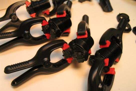
About a year ago LSP staff received a copy of the Wright J-5 engine from the fine folks at Williams Brothers Inc., for reviewing. You can check what´s in the box here at LSP. Well, after building a Testors´ Spirit of St. Louis in 1/72 scale, I decided to build this engine to show them both side by side in a commemorative display for the 75 years of Lindbergh´s transatlantic flight. I´m a couple of years late by now... Anyway, here is the J-5 engine, a large deviation from what we are used to build, but an excellent opportunity to try new techniques on something very different.
As I mentioned in the review, a careful reading of the instructions is really necessary in this case since there´s no wings or fuselages. After removing most parts from the sprues, those less obvious were numbered with a permanent pen to avoid confusions later. In addition, the parts were grouped according to the instructions steps in plastic bags and film canisters. Tiny or very fragile parts were secured with tape on a card paper and their numbers noted.
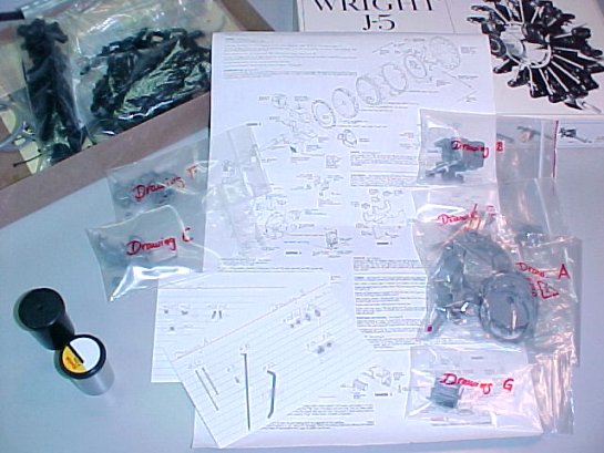
It is imperative to be organized with this kit.
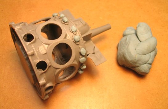
The quality of the molding is below what we could expect today, so I spent a lot of time making the initial clean up and sanding. Once the most parts were ready, I started assembling the major subassemblies (crankcase, magnetos, carburetor and intake manifold) using MIBK (methil-iso-buthil-ketone - my long time favorite cement) . The big pieces are molded with a lot of imperfections, intentionally done to replicate the cast metal used. Sometimes the effect is a bit overdone, making difficult to distinguish what is an intentional surface effect from what is a bad mold effect. In any case, I opted to leave most of them as is, just with a light sandpaper pass. After assembling the crankcase and reduction case with the propeller shaft between them the pushrods bases were sanded as flat as possible to eliminate a nasty seam mark. The same treatment was applied to the cylinders bases.
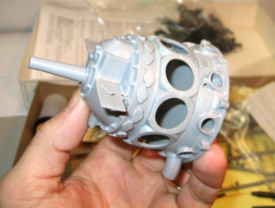
It is just an engine, but nothing small.
Next the intake manifold and carburetor body were assembled, and huge seams showed up, no matter how well you sand the parts. In some areas tight seams were left to replicate joint lines of the real machine, but in some others they simply should not exist. Anticipating the use of a lot of putty, I also assembled the exhaust and intake pipes at this point, and applied a generous amounts of thinned Squadron green putty on all necessary parts.
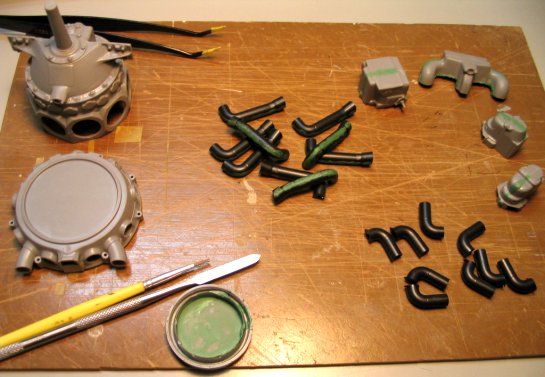
Applying thinned putty to dozens of seams. A couple of them were 1mm wide!!!
After spending almost a square meter of rough sanding paper, I went back to all seams and applied a good coat of Mr Surfacer. Once dry, I finished the parts with wet-sanding. I also simulated some weld lines with stretched sprue in a few places.
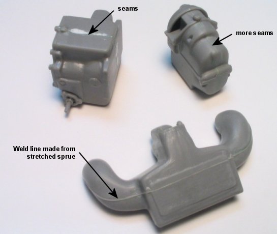
Some major parts trued and ready for priming.
The cylinders were assembled next, and here I found another difficulty. During the dry fitting of the cylinder halves, I noted that when the cooling fins were aligned on the lower cylinder they misaligned on the top area. I elected to keep them aligned where they would be more visible, but the decision would bring me a heavy sanding job afterwards.
Cylinders assembly line.
The carburetor heater housing halves should be assembled with the bypass valve between them. However, that would prevent cleaning the resulting seam lines on the inside. Instead, I cut the bypass valve hinge pins and drilled holes to install the valve after painting using brass pins.
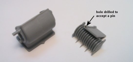
The bypass valve was modified to enable its assembly later.
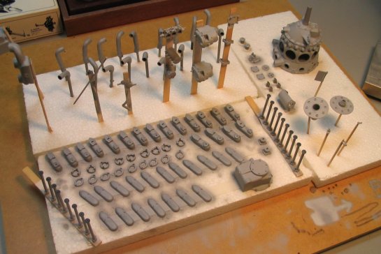
Most of the remaining kit´s parts were then removed from the sprues, cleaned and treated with a Scotch Brite pad. A very boring - but necessary - job.
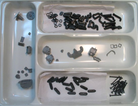
Parts drying after washing them with soap and tap water.
Now everything was ready to start priming, except for the cylinders (I decided not to prime them as they would be painted black).
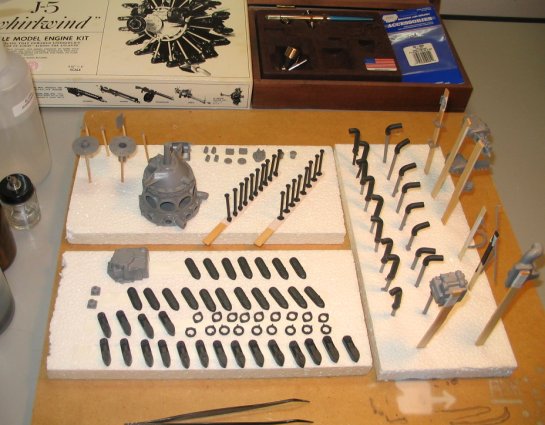
Let´s start priming.
Before putting the airbrush in action, areas that would require further cementing were masked. In particular, I drilled holes in all pushrods bases (to provide room for the glue) and masked them with silly putty in order to leave some bare plastic to the cement bond on. The rear area of the engine was also masked where the carburetor will be butt jointed.
Using silly putty to preserve some bare plastic aread for cementing.
Finally, heavily thinned Mr Resin Primer was airbrushed all over the parts. I almost went out of primer, but it was worth since I found many spots requiring further filling and sanding.
Parts drying after priming.
Then the application of the top colors started. I used only automotive lacquer (a Brazilian brand called Aerotech - airbrush ready, pre-thinned and retarded - for modeling use) up to this point of the project. After assembling the rocker boxes and their covers, I shot gloss black on all 18 of them.
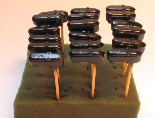
The rocker boxes after painting with gloss black.
Before going on, I had to stop everything and try to eliminate the quite visible seams on the top of each cylinder head. Very frustrating, because it was impossible to reach all spots. A heavy scrubbing with Scotch Brite helped to smooth things there. The cylinders, intake and exhaust pipes and the cylinder bases were then painted flat black. I´m a believer that pure black doesn´t exit in plastic modeling, but given the scale of this one I made an exception and shot it straight. Later, I applied a heavily thinned mix of some left over gloss black on certain areas of the intake pipes and cylinder heads. This resulted in an interesting effect contrasting with the dead flat of the cylinders, sort of simulating oil and grease migrating to flat black regions. The exhaust pipes will eventually receive a proper weathering to simulate soot and burnt metal.
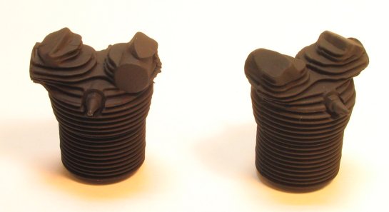
The cylinder heads after a shot of flat black.
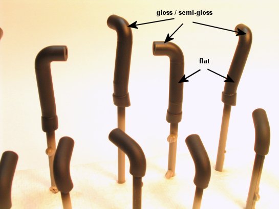
Different effects achieved using gloss paint over some flat black areas.
I in general don´t use pre-shading techniques due to my insistence in overshooting the final colors. This time I was decided to make it right, anticipating the use of typical engine-grey color on the larger subassemblies. And so I shot flat black around recesses, bolts, joints etc.
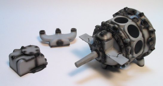
Pre-shaded parts.
I mixed neutral grey with a bit of flat white to make my own interpretation of engine gray and airbrushed over the primed parts. The pre-shading worked, and I´m satisfied with the result. The photos below don´t do justice to the effect achieved, but I still think I overshoot the top coat again (in spite of thinning the paint more than I usually do...).
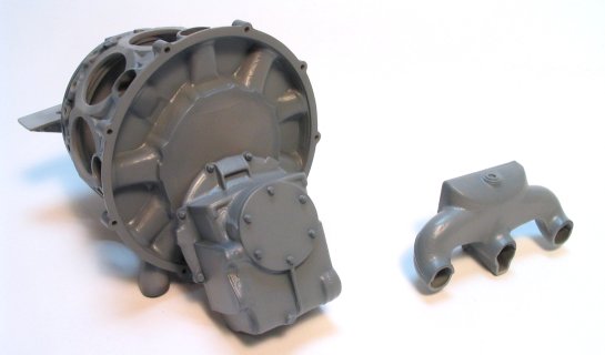
Parts painted with heavily thinned engine gray.
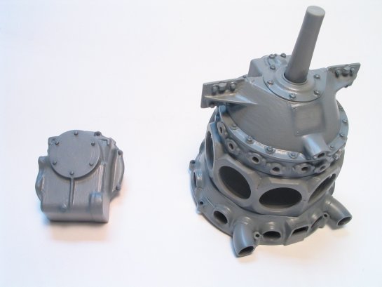
Parts painted with heavily thinned engine gray.
The instructions (and engine photos) call for natural metal bolts. I´m already worried about how to replicated this on so many molded on bolts. I´m also very disappointed with the rubber parts, and probably will discard them for scratchbuilt replacements. So, I can´t claim the hard part has gone yet...
Part 1 | Part 2 | Part 3 | Part 4 | Part 5
© Rogério ´Rato´ Marczak
This article was published on Wednesday, July 20 2011; Last modified on Saturday, May 14 2016