
Merlin Engine Cutaway
Photos By Max Otten
Photos were taken at the South African Military History Museum, Johannesburg (South Africa) in 2015.
The museum has two Merlin engines that have been stripped of paint and polished. Although obviously not in their original colour, it makes detail much more easily visible than on their standard black-painted counterparts. The engines are displayed in glass cabinets which occasionally makes flash photography a bit difficult so if you see odd features in the photos, remember that they just might be reflections.
This particular engine was not identified by version but it has a single-stage supercharger. The special thing about this engine is that pieces have been cut away so you get a look inside its innards.
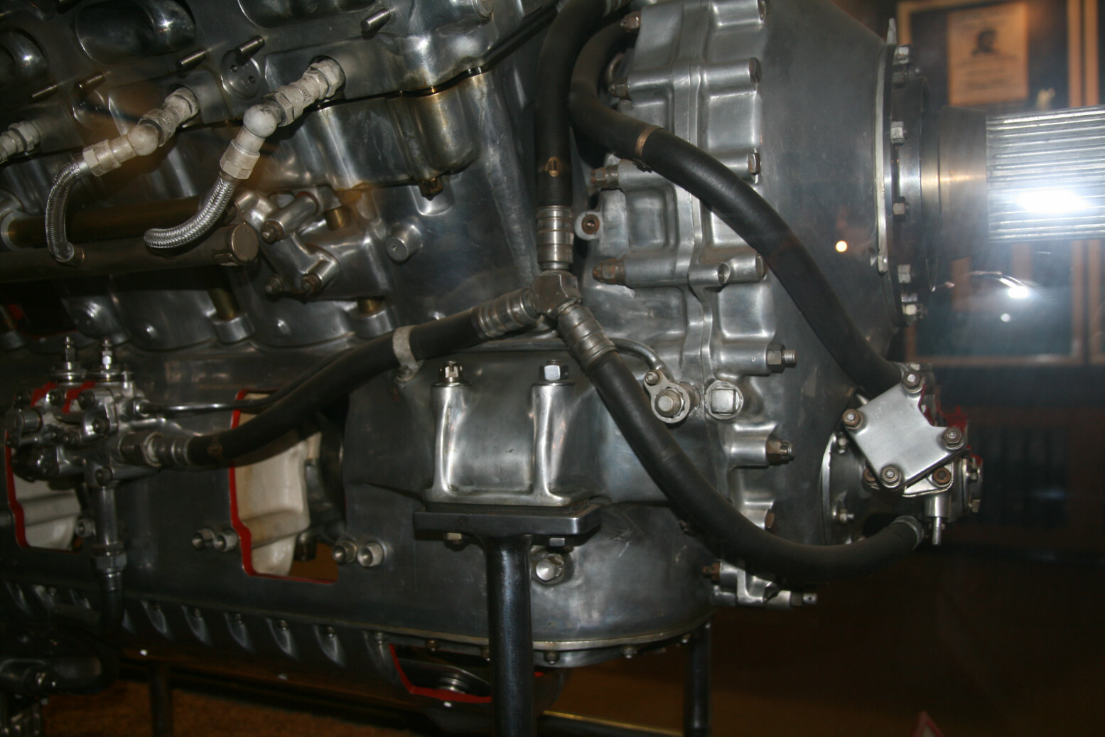
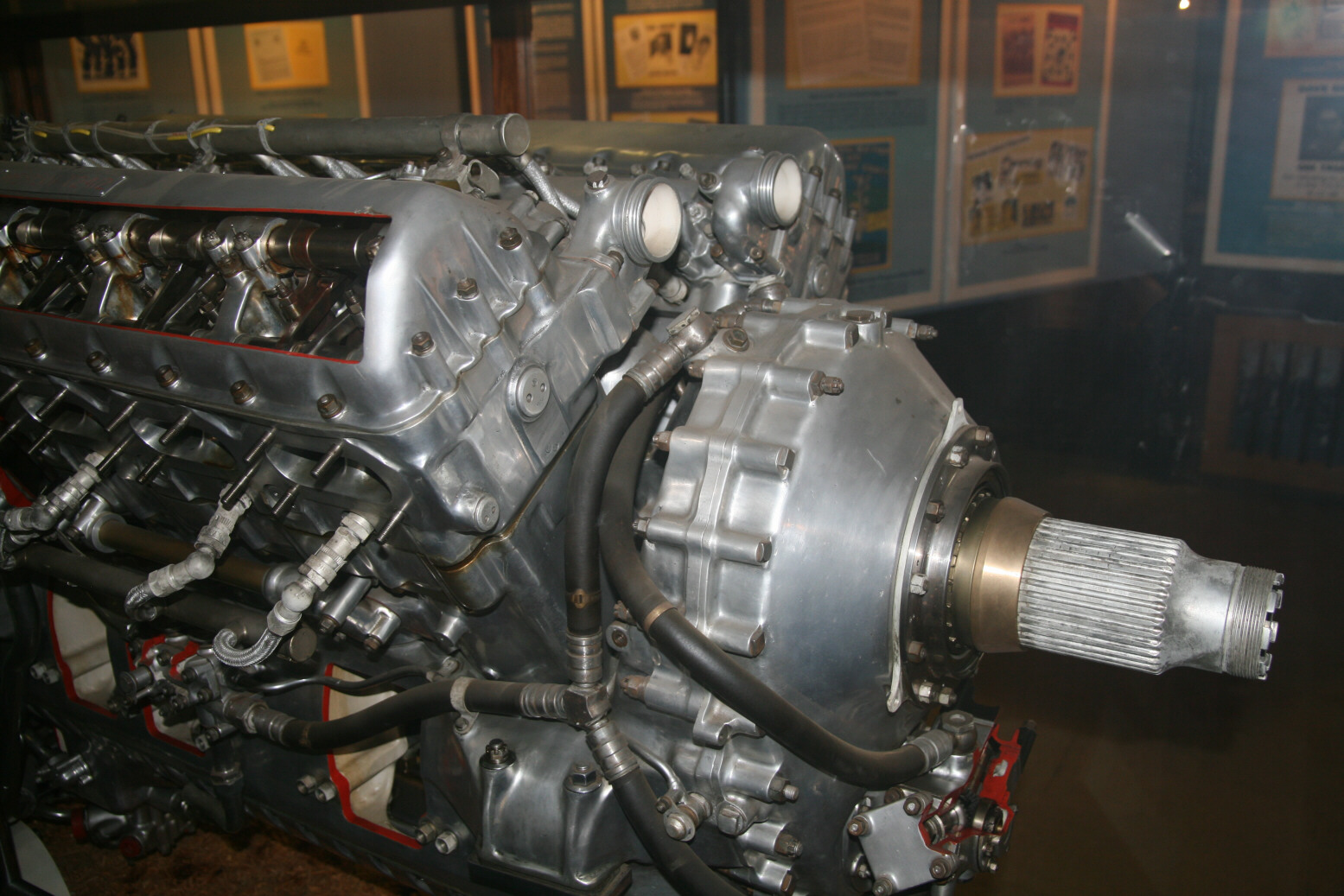
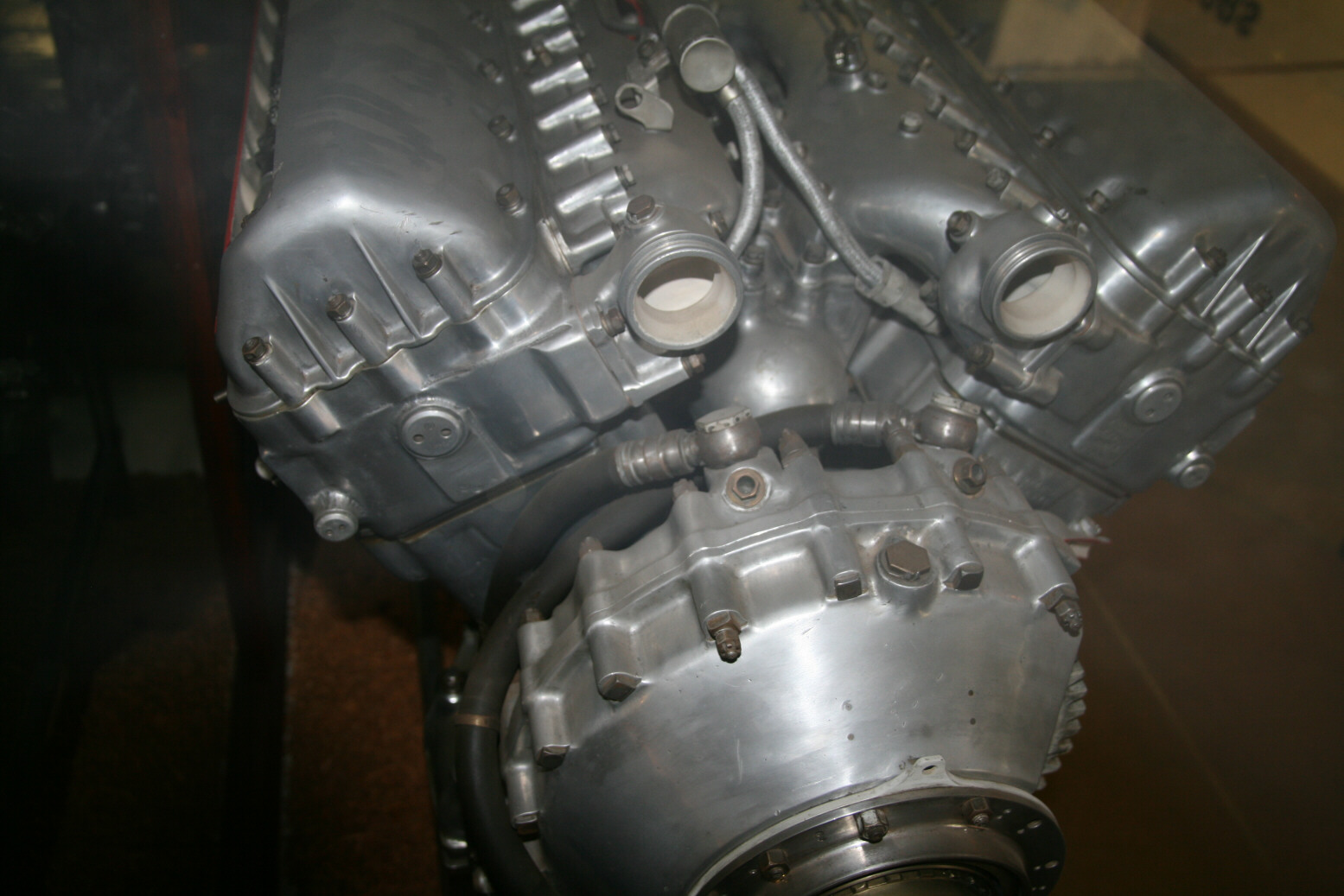
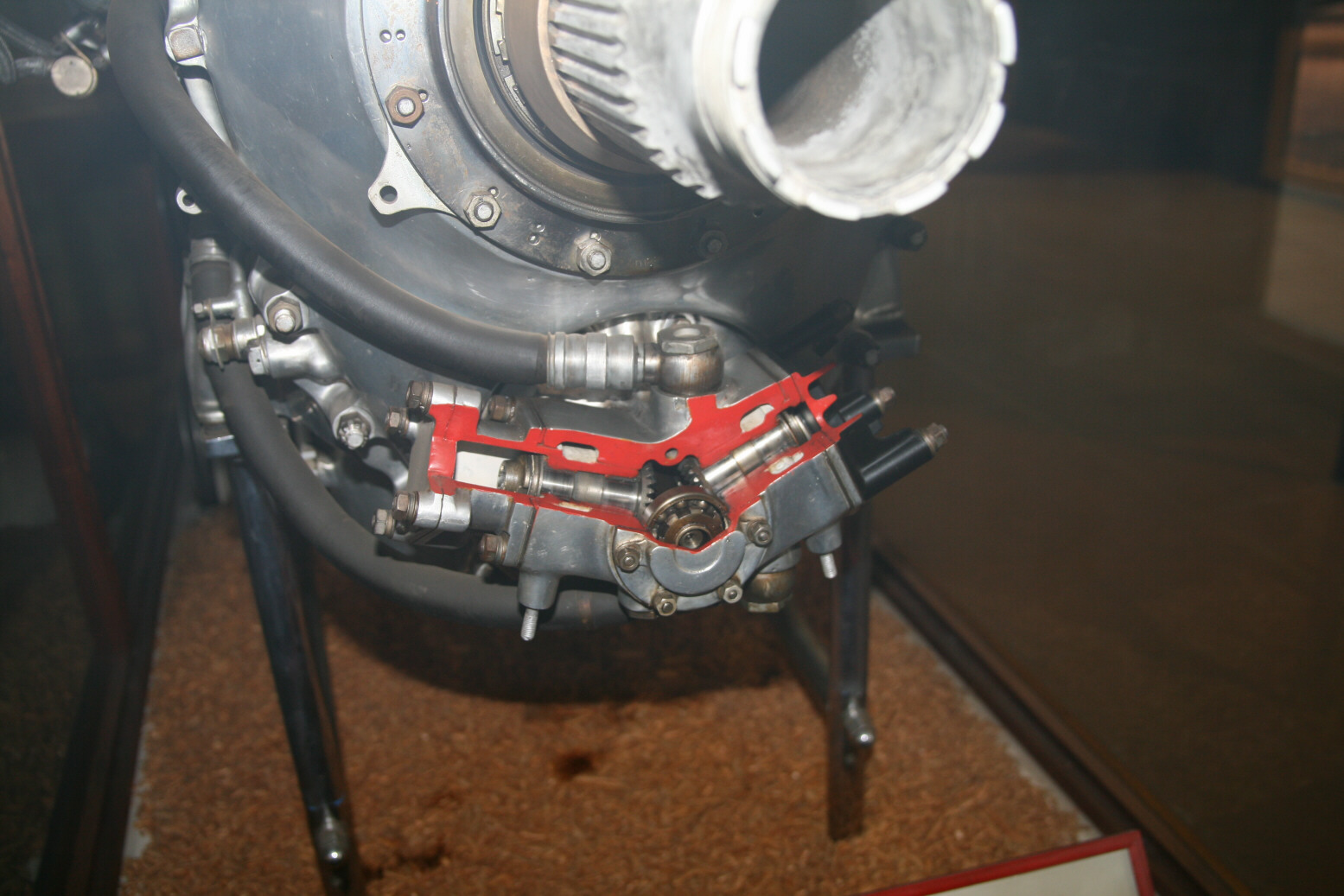
Photo 1 (above) starts of at the starboard front. At the far right (with the flash reflection) is the propeller axis with the grooves. Towards the left follows the reduction gear in front of which run oil pipes that are connected to the oil control unit on the far left and the vacuum pump on the right. The two pipes that go into the vertical direction plug into the reduction gear at the top (photo 2). In photo 2 (above) you see part of the valve cover cut away with the valve rocker shaft visible (more detail later). Photo 3 (above) does not have any cutaway but you see the top front of the engine with the reduction gear up front and above that the two outlet pipes of the cooling system. These pipes would be connected up with the coolant header tank. What you can see very well here is that the parts that are between the rocker covers and between which the ignition cables are running to the spark plugs are not flat plates but thick channels through which the coolant runs from the cylinders. They are bolted onto to the big pipe with a bulbous front in the centre between the cylinder banks (the torpedo-like front is visible behind the connection points of the two oil lines on top of the reduction gear). This pipe is the one that is at the end of the supercharger. The ignition cables (visible for the frontmost spark plugs) come from the pipe of which you can see the flat end above the left exit of the coolant. Photo 4 (above) shows the cutaway vacuum pump with the oil line connection.


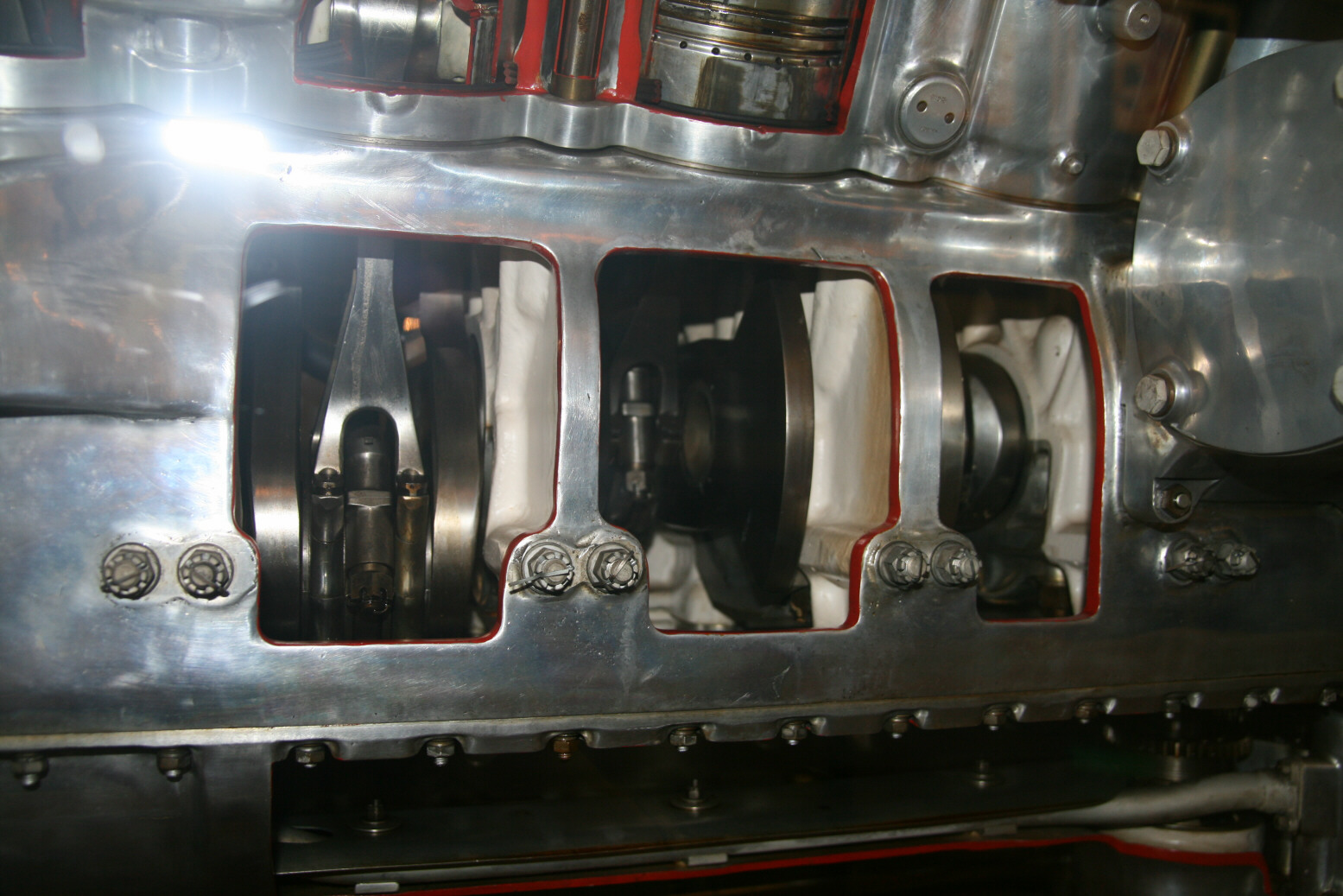
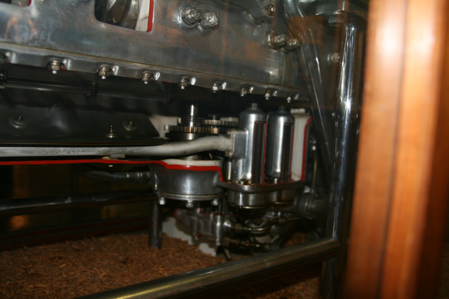
Photo 5 (above) shows the cutaway reduction gear with the large gear-wheel that connects to the propeller axis. There are smaller gear-wheels hidden underneath that connect the large one to the crankshaft. Photo 6 (above) shows the port side of the engine. On top are the exhaust valve springs. The large rod between the cylinders is one of the series that holds the cylinder block top in place. Above the cylinders/pistons you see the exhaust valves (those of the cylinder on the right are open). Photo 7 (above) is further down and shows the crankshaft. You can see that the sets of double bolts on the outside hold the frames that keep the crankshaft in position. Photo 8 (above) shows that about half of the engine bottom has been cut away This is the area where the oil gets collected and pumped to the oil cooler in the wing.
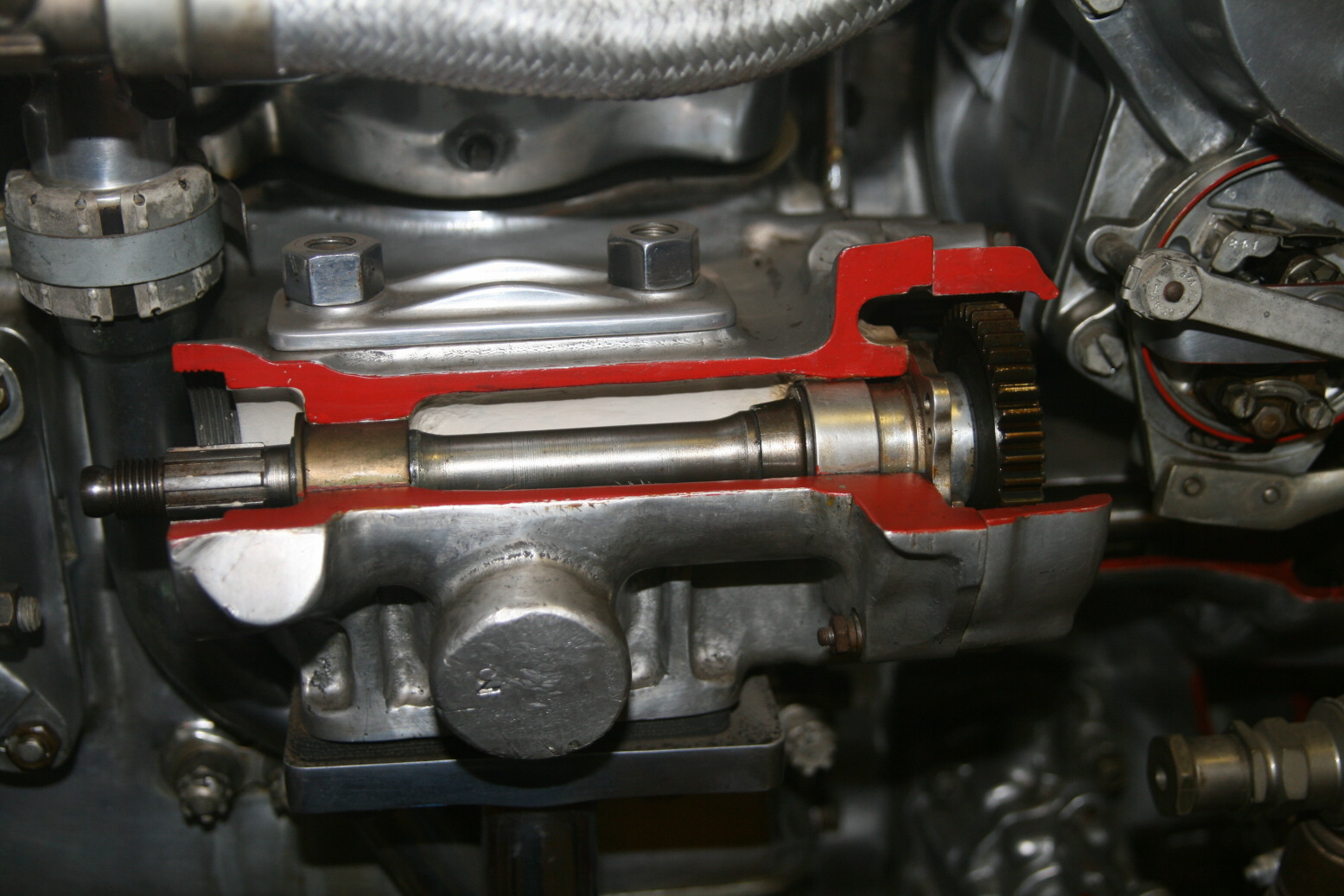
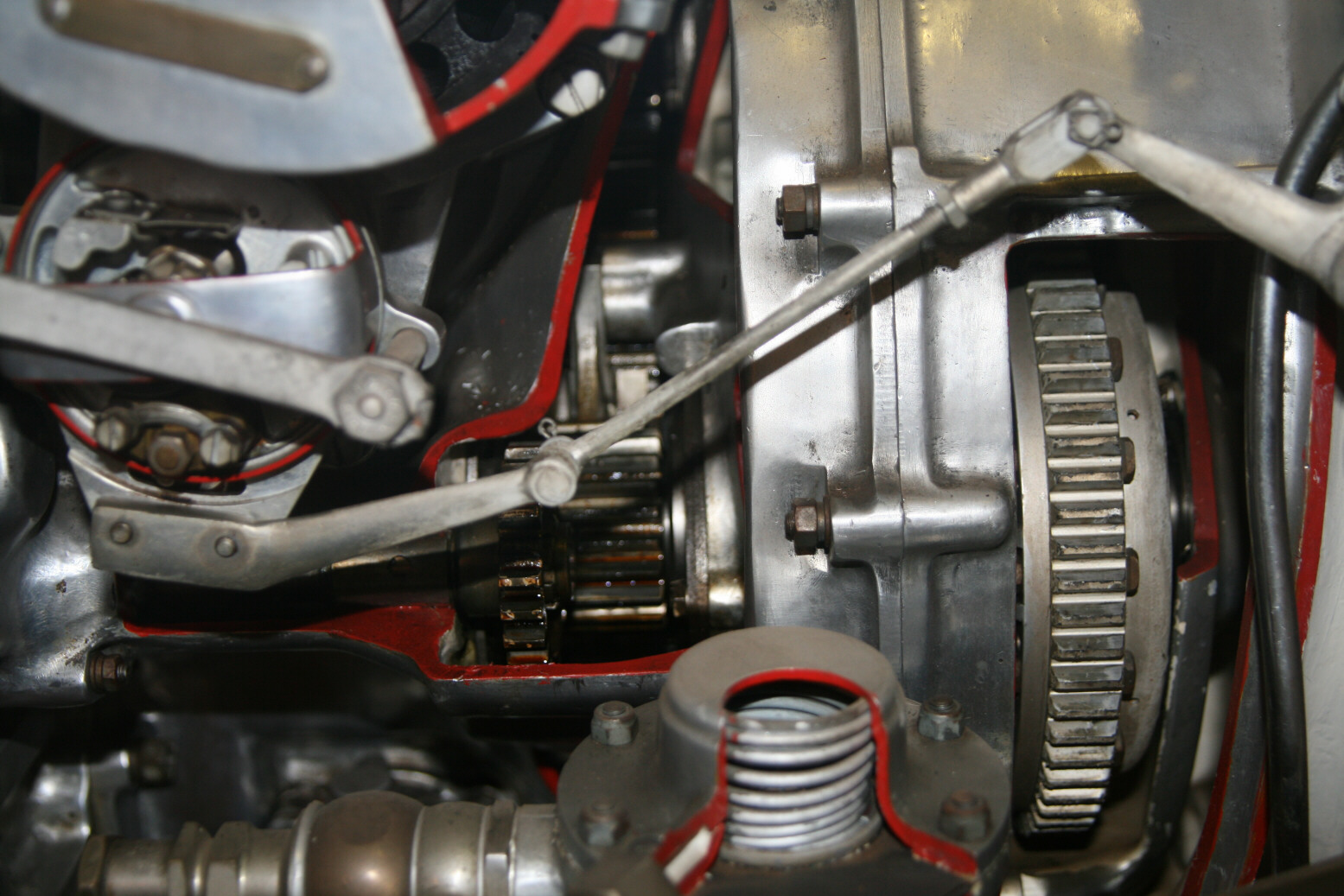
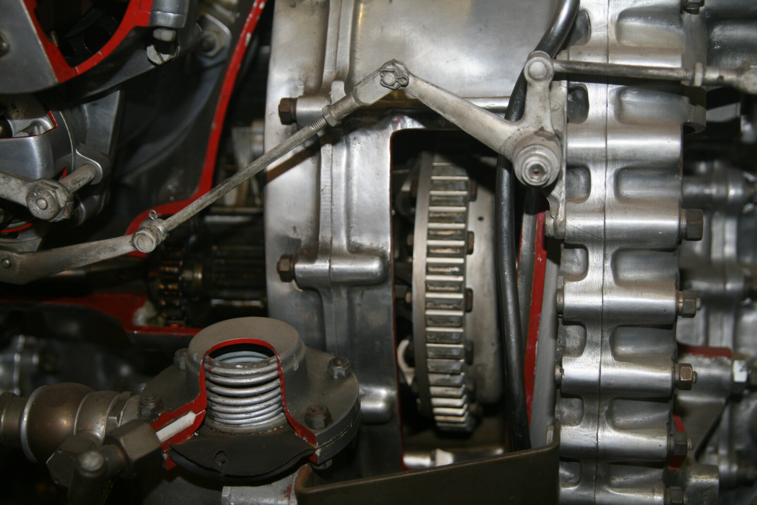
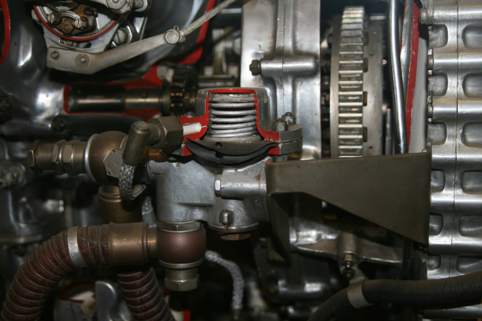
Photo 9 (above) shows the gear for the generator (which itself is absent here). On the right-hand side you see part of the inside of the port magneto. Photo 10 (above) shows the rods of the magneto advance control. Behind that you see in the cutaway part of the gear for driving the supercharger. The spring in the cutaway up front (bottom) is at the top of the fuel pump. Photo 11 (above) shows the same area but from a slightly different angle. Photo 12 (above) shows the fuel pump which is from a type that I haven’t seen before.
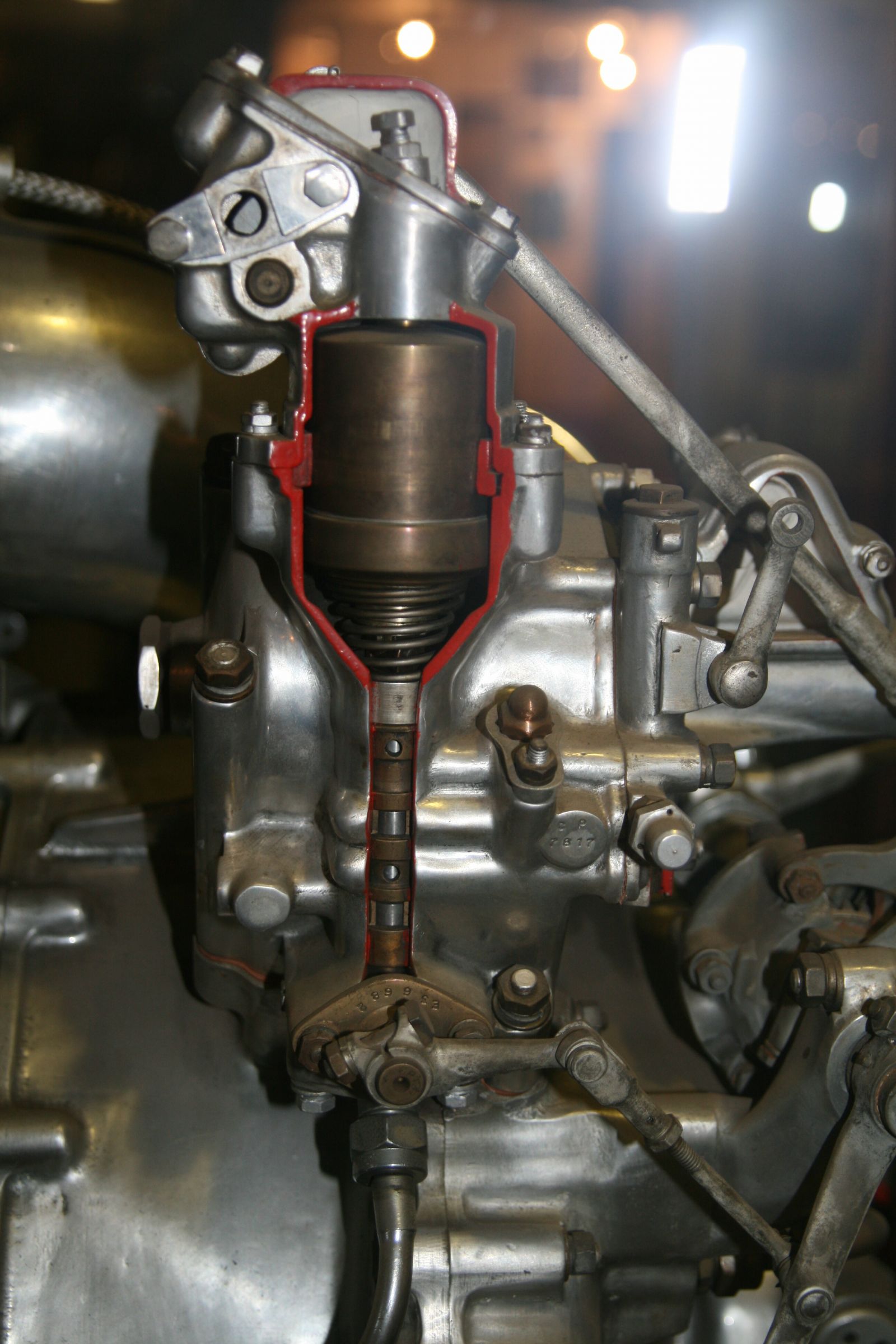
Photo 13 (above) is the boost control unit above the supercharger. This is the manual boost control as the control rod is visible behind it.
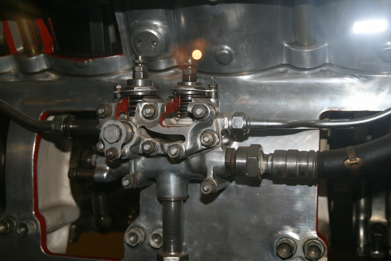
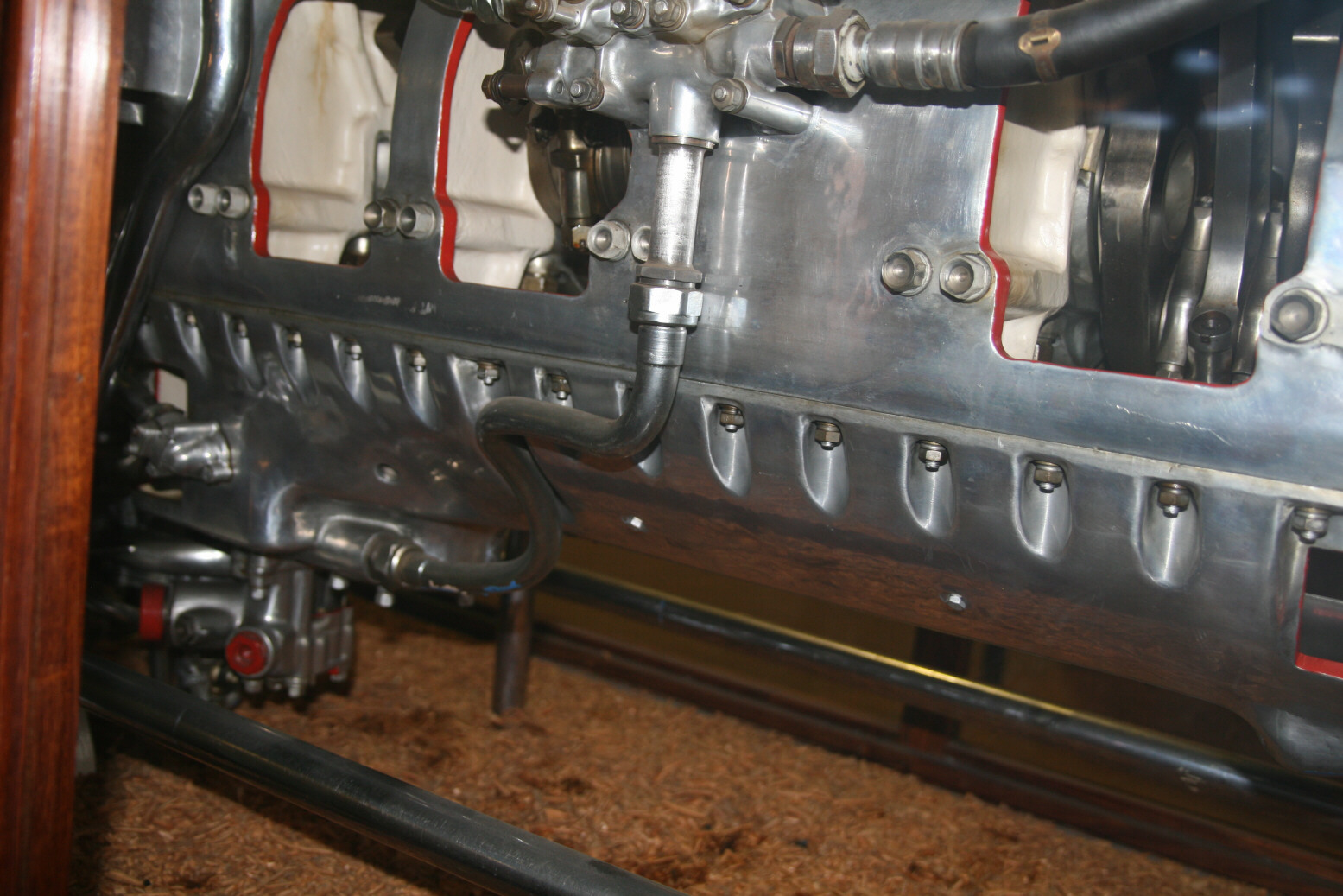
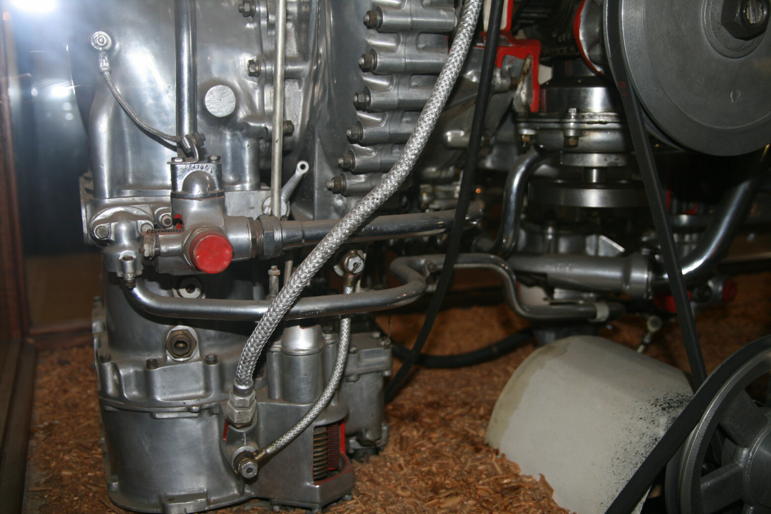
Photo 14 (above) is the oil control unit on the starboard side of the engine. It is located at the bottom of the cylinder row, roughly in the middle along the length of the engine (see also photo 1). Behind it you again see the crankshaft, this time from the other side. Photo 15 (above) shows the pipe that connects the oil control unit to the oil pump at the bottom. Photo 16 (above) shows the bottom of the supercharger air intakes with its coolant connections. The carburetor at the bottom has been cut open. The pulleys and drive belts on the right are not part of the engine. They are located at the point where the starter engine would have been and I guess they were intended to show the engine parts moving in the display.

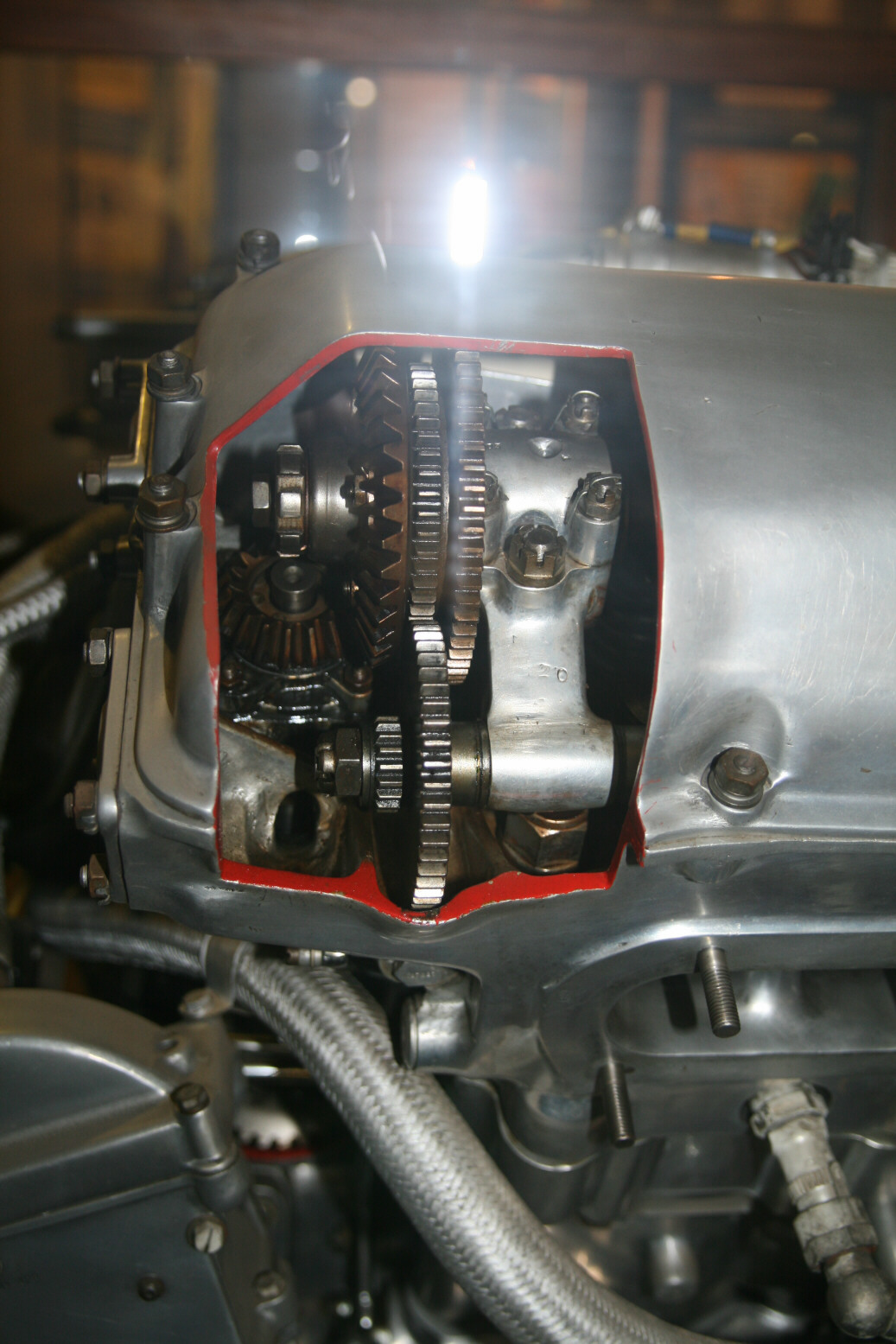
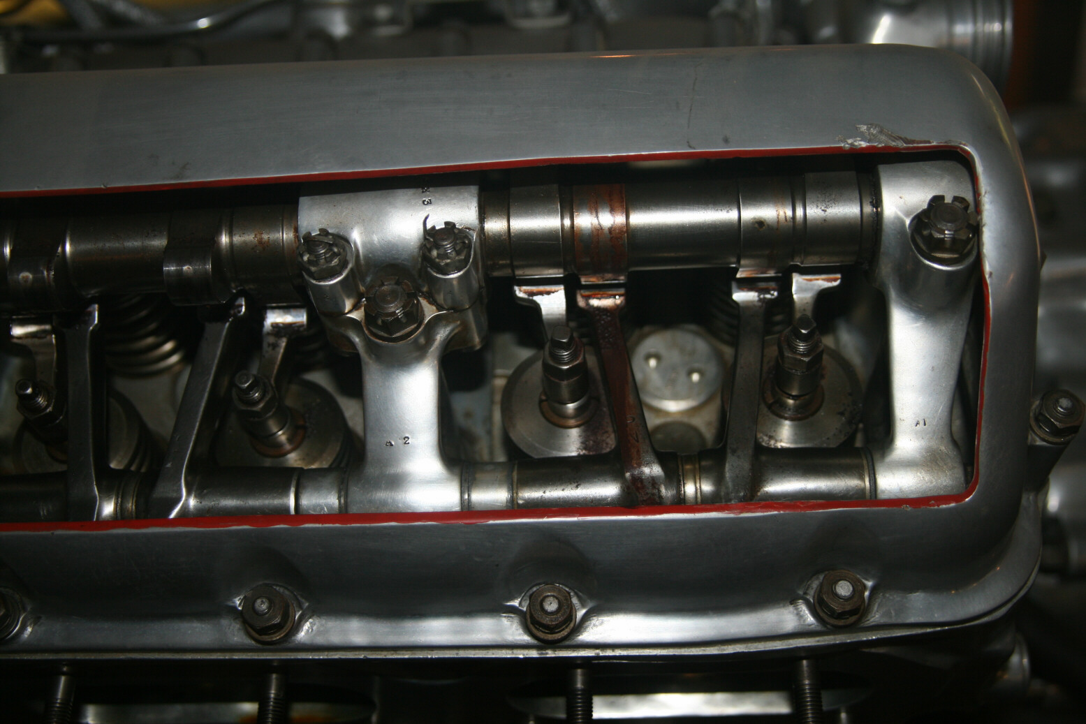
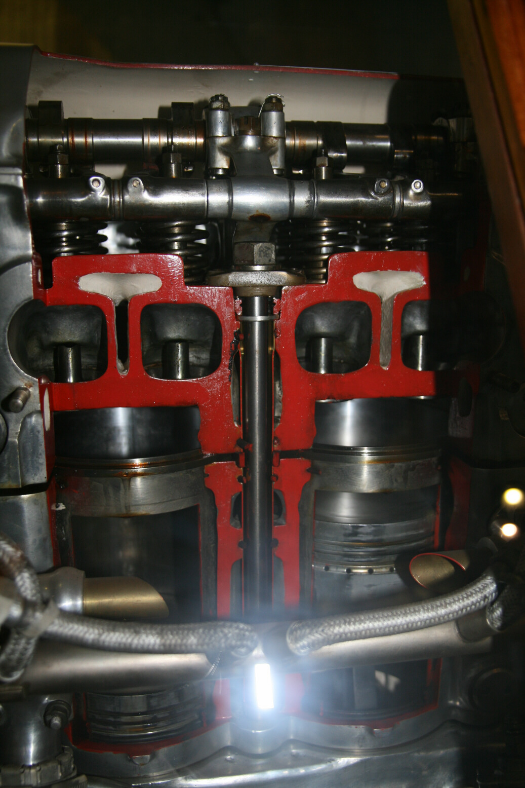
Photo 17 (above) shows the top of the supercharger. Front right is the starboard magneto, with behind it the ignition cable coming from the other side (the starboard magneto feeds the inner spark plugs so it has a single cable that goes up between the cylinder banks, while the port magneto feeds the outer spark plugs and has cables running on either side of the engine, with the one to starboard crossing over underneath the supercharger pipe. Far right you see the gears that drive the valve rockers. These gears in turn are driven by a shaft that comes up parallel to the ‘vertical’ direction of the cylinder bank. You can just see its top popping out behind the port magneto cable (just left of where that is clamped to the starboard magneto). The open slit near its top is a cutaway Photo 18 (above) shows the rocker shafts gears from another angle while photo 19 (above) shows the shafts, rockers and valves from the top. Photo 20 (above) shows two cylinders cut away to half width so the valves you see are the fuel inlet valves more towards the engine centre. The exhaust valves have been cut away here.
© Max Otten 2015
This article created on Wednesday, June 24 2015; Last modified on Thursday, March 31 2016