
Flightpath | Hawker Hunter Display Set
Reviewed by Steve Allen
Consisting of a large etched sheet of brass and a collection of cast leadlike pieces the first thoughts are, what a difficult job this is going to be, why didn't they cast it in resin. The complexity and detail incorporated is excellent but does require a level of complexity such that it is better to improve your skills by starting on the easier pieces first.
So let's begin.
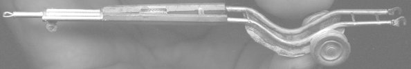
Hunter Tow Bar
Start by cutting and cleaning up the four parts that make the ladder spacer. A sharp knife is important to prevent bending or otherwise damaging the frail brass components. It is very likely that some of the sprue remains after removal so out with a needle file and pair of small pliers. Everyone has their own techniques but I use a combination of the following. For large parts that can be hand held I use the needle file carefully running along the brass rather than across it as this is likely to bend it. Alternatively hold the brass in the pliers so that a minimal amount of required brass protrudes, as well as the area to be removed. Careful slow filing should not cause damage.
Where parts are to be fixed to the flat side of another part the designer has thoughtfully etched a groove so either apply glue to the edge of one part or mate them together and apply glue to the join.
The ladder section requires that fine brass rod be used to create the three required "rungs". Fit overlength pieces of rod into the predrilled holes and adjust the width to match the die cast extension. Then glue and leave to dry. The excess can then be trimmed and filed flush. I found that the ends of the ladder required filing to ensure that when assembled the whole unit is straight. Now glue the "fishtail" section, I found that a bit of twisting and tweaking was required for a fit with the minimum of gaps. You may find it easier to tweak the cast rods before assembling into the ladder. Ample use of thick superglue filled the small gaps left by my construction requiring only a clean up afterwards. The two piece hooks now require folding and gluing. Fixing the other few parts completes the assembly into a nice looking towbar.>
One of the nice things is the choice of colour schemes available, depending on the era. Initially they were painted RAF blue/grey. They were then painted red and ended up green.
It seems from my archive of photographs that several designs were tested including a much simpler version created from a single tube curved like this model and ending in a U section holding the tow hooks. This version had smaller wheels.
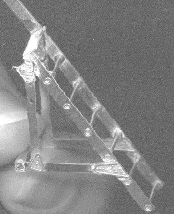
Hunter Access Ladder
This requires the cutting of 6 ladder rungs from the same rod used in the construction of the towbar. Cutting rod to 11.25mm is a bit tricky so instead I cut one over length and filed it down until is matched the length of the top rung now use this one to cut the other five. For easier construction the side pieces are made of two plates glued together to give the required thickness. The inner pieces have holes to locate the rod rungs, making assembly much easier and the outer pieces have the correct detail. The construction diagram has been simplified by only showing the nearside supports. This does require a little bit of thought to get the correct angles and how the pieces fit. Its not too hard but dry run the positioning before hitting the glue. I carefully scrutinised the few photographs that I have showing the real thing and soon decided that at least three designs were prevalent in use. The only real disappointment was that I was unable to line up some of the holes taking one of the rods on the attaching mechanism. (This ladder was mounted into a hole covered by the small oval panel under the left side of the cockpit) If you are intending to fix the ladder to your model, cut this panel out and fix a false cover above the hole. Fix a block of filler on the inside and prepare for drilling the hole taking the fixing rod. The photos I have do not show the detail behind this panel, presumably some kind of locking device on the mounting tube. This is inclined upwards from the aircraft at a slight angle. For extra authenticity build the ladder and leave the supports off. Fix to the drilled mounting hole and position the ladder. Now you can set up the supports for best fit. It's a bit fiddly but the result looks fantastic. A choice of colours is also available for this item, being painted red, blue, yellow or green in later service.
Hunter Gun Pack Trailer
This item is a bit tricky consisting as it does of very small parts with curved edges. Constructed mainly from two cast parts, ensure that they are both square as one of them was twisted in my kit. (Easily corrected with a couple of pairs of pliers) It is also essential to construct the removable bar that fits across the back of the trailer first. This is necessary to ensure that the completed trailer is Square. A certain amount of care is required when building the frame (sides and the folded front part) as there is little mating area for the glue to adhere to. The plans recommend soldering. After re-gluing the joint twice I made up some block to it into the corners. Out of view these stiffen things up nicely. Mounting the wheel hubs but leaving the wheels unglued allows for easier painting later. The pantograph mechanism for the forklift section is probably the fiddliest bit of bending and construction in the whole kit. It is a bit difficult to describe but if you buy the kit all will be obvious. Finding a piece of rod the correct thickness for the item to be curved to and clamp this aligned along the fold mark on the brasswork. Careful bending of the brasswork should then lead to a suitably curved part. Now the ends can be folded and glued. By carefully using some fine rod for hinges the forklift mechanism can be made movable, and stiff enough to be position up or down. Cut the rod to length so that small amount protrudes, install and dab a small amount of glue on the stub. In real life they were probably large bolt ends. Finishing up with the Hydraulic pump, extra detail can be added in the form of pipework and even a cylinder. A very detailed and neat bit of kit allowing several variations in displaying along with the gunpack and cradle.
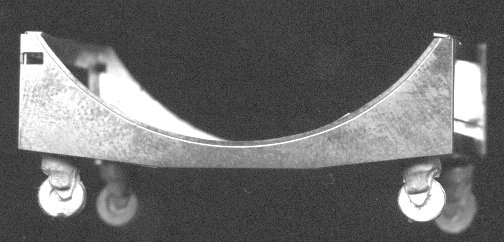
Hunter Gun Pack Cradle
Very little needs to said regarding the construction of this part other than it uses the two parts un-numbered on the sprue from the Trolley section. Also don't glue part one to it, as this is the base of the gun pack itself.
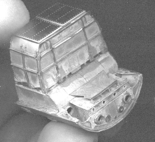
Hunter Gun Pack
The most daunting piece of construction is now upon you. With many complex folds required, careful planning is necessary before you bend your first bit. I started on the Ammo box covers, these two small parts require very fine bending, and I used a pair of very small pliers bending progressively down the edge and back a small amount at each time. Once bent to 35 or so degrees the bent bit can be placed on a hard flat surface and bent to 90 degrees, giving a nice hard edge. Now flatten out any wrinkles with pliers held side on. Construction can be continued leaving all the fine detailed bits off until after the main construction has been completed. The fine detail parts are so fine that they may easily be damaged if fixed before the heavy duty bending is completed. (the lifting rings are so small that they were positioned dry with a pin through the hole and glue added from behind. I added them just prior to fixing the ammo box to the gun housing.) Build into two main parts, the Ammo Box and the Gun housing. When assembled the design leaves a largish gap where you would expect to see the ammunition folded neatly. To fill this space up I constructed a simple rectangular box from plastic card to fit inside and behind the gaps. This will be painted a darker shade once the airbrushing is completed. I also found that part 22 seemed to detract from the overall appearance so was left off. Now for the gun housing, great care must be exercised when folding the main part as the diagrams are simplified and do not entirely clearly represent the finished configuration. Also the bits are very fine and fragile until attached to the outer panel. Piece number 1 should be curved to the radius of the hunter fuselage and unfortunately the manufacturer has etched grooves on the inner surface to make fixing to the inner workings better. I wish they hadn't because as soon as you start to bend the curves these weak points bend into v shapes, aaaaaaarrrrrrggggghhhhhh! Your best bet is to clamp one end to a Tamiya paint jar or similar sized round tube and then bend around it. This will result in a curve very slightly to large. But this makes fine tuning the curve a hand held job, being careful of those grooves. Now after carefully fixing the curved panel to the gun housing and this to the ammo box you can start adding the really fine detailed bits. To create the tube like fixings that represent the attachment collars to the gun barrels and spent case chute first remove all the rings and group them as only one of each size is numbered. Place them over a needle file in order will line them up then remove tightly held between finger and thumb and add a drop of glue, voila they can be added after allowing to dry. This item was bare aluminum as the wheel wells but should be dirtied down a bit as fumes from the guns could stain the unit.
You now have the most finely detailed and beautifully constructed etched metal kit that I have ever had the pleasure of building. Ok so it did test the brainpower and dexterity a bit but you won't be disappointed with the final results.
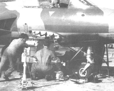
The big decision now awaits you, how to display them with the magnificent Hunter. The Gun pack is probably best mounted on the trolley but it can be fitted into the trailer or positioned separately, with the bar left open. You must also decide wither to cut the panel from the hunter model to leave a gap for the new gun pack, note that the tail end of the hunter was propped up to prevent tail sitting when swapping packs. The link collector blisters were divided into two parts front and rear and were attached to separate panels on the aircraft. The fitting of the Revell ones are slightly too far forward. To remove the gun pack the front half of the blisters were first removed so the pack would fit into the cradle. The back part could be left attached to its panel, which had to be removed to line up the case ejection chutes. These rear panels could be removed as single units or the blister halves could also be separated. ( it is impossible to say from the photographs that I have seen whether the halves of blister were open to each other on the inside or separated by panels. The fact that in some Swiss aircraft equipment was fitted to the back half seem to me that it was merely an aerodynamic fairing, all the links being collected in the front half.) The panels in front of the gun pack also had to be unfastened, sometimes they were removed completely, or left hinged along the outboard edge, dangling from the fuselage. To winch the pack up and down a winching devise was attached to each side of the fuselage over a protective oval fishplate. The device, seen standing in the photograph contained a pulley wheel in the top end where it attached to the mounting on the side of the aircraft. This could be pivoted outwards so that the operator could hold the gearbox and handle at a convenient height. the cable was slung under the unit, the pack sliding down rails. The 8 eyes at the top of the ammo box fastened things in place.
To aid you I have included a rare photo of the installation process. As these gun packs were interchangeable from aircraft to aircraft it was not uncommon for the paintwork to be slightly out of alignment.
So now you can create a very detailed diorama with as much colour as you wish. Red, yellow, blue or green.
© Steve Allen
This review was published on Saturday, July 02 2011; Last modified on Saturday, January 13 2018