
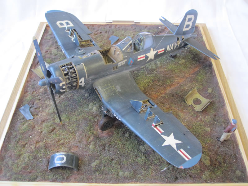
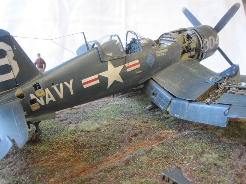
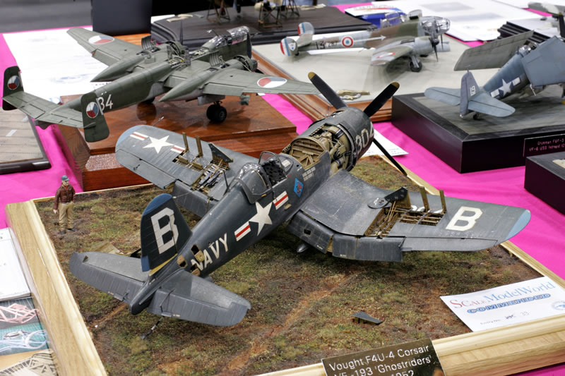
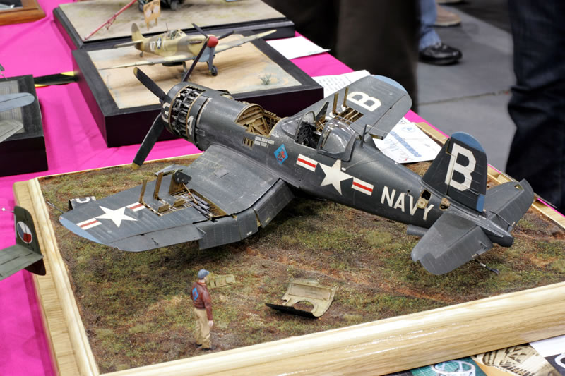
Trumpeter 1/32 F4U-4 Corsair - VF-193 'Ghostriders' Korea 1952
By Rich Carrick
Introduction
After a hiatus of 17 years I made a return to the wonderful world of scale modelling about a year ago whilst recovering from an illness, and the decision as to what to build was taken out of my hands when I received the Trumpeter 1/32 F4U-4 Corsair as a gift - thankfully I have always liked the look of this aircraft.
I started researching and straight away realized that things have moved on significantly in the years I have been away, both in terms of available aftermarket accessories, and the amount of excellent reference material available at the click of a button. I found a particularly good source of images of a Corsair that is being restored in the US, and with the kind help of the project director I was ready to go. I also enlisted the help of several other kind individuals, from modellers to warbird pilots, so a big 'thank you' to them.
About the F4U Corsair
Early in the Pacific War, US Navy and Marine Corps fighter pilots found themselves outclassed by the agile and well-armed Japanese A6M Zero, but even then work was underway to provide them with better aircraft. One of those better aircraft was the Vought "F4U Corsair", a rugged, powerful, and somewhat unforgiving aircraft that featured a distinctive inverted gull wing.
The Corsair proved more than a match for the Zero, and it would also prove to be an excellent fighter-bomber, serving in this role in the Korean War and in the French colonial wars in Indochina and Algeria.
The last major wartime production variant of the Corsair was the "F4U-4", which featured a P&W R-2800-18W Double Wasp with 1,567 kW (2,100 HP) takeoff power and water-methanol injection. The only visible differences from the F4U-1D were an inlet fitted in the lower lip of the cowling, giving the aircraft's nose a slightly different profile, and a four-bladed propeller. All following Corsair variants would retain the four-bladed propeller. Five F4U-1s were modified as "XF4U-4" prototypes, with the first performing its initial flight on 19 April 1944. One of the prototypes was fitted with a prop spinner, but this item was not adopted for production. Initial flight of a production F4U-4 was in September 1944, with initial service deliveries in October. A dozen (some sources claim only two) F4U-4s were built by Goodyear with the designation of "FG-4", but the end of the war led to cancellation of further Corsair orders from Goodyear. However, the Navy was still appreciative enough of the F4U-4 to obtain about 400 more from Vought after the war up to 1947. 2,037 standard F4U-4s were built in all.
During the Korean War, the Corsair was used mostly in the close-support role, and it was a Korean War bird that I finally decided to build, mainly because information was sketchy for WWII 'dash fours', and the Korean era aircraft were much more colourful.
The Project
I decided from the off that I was going to try and build a unique 1/32 Corsair. During the course of my research it became apparent that although several modellers have added significant details to their builds, there were certain areas that had not been attempted 'properly' before, such as the tail wheel well, the gun bays, the engine accessory compartment and the fuel cell bay.
First of all I gathered as much as I could in the way of old fashioned printed reference material, and also detail sets. The kit uses the following aftermarket bits:
- Aires F4U Corsair resin wheel wells
- Aires F4U Corsair resin gun bays
- Grand Phoenix F4U-4 Corsair resin replacement cockpit set
- Jerry Rutman F4U Corsair resin 4 bladed Hamilton Standard prop & hub
- Jerry Rutman F4U Corsair diamond pattern resin wheels
- Vector P&W R2800 C (late model) resin engine
- Mike Grant decals data placards (various scales)
- Custom masks and decals by Ad Astra masks
and the following reference books were used, alongside all of the info I found online:
- F4U Corsair In Action - Squadron Signal Publications
- F4U Corsair Modellers Datafile - SAM Publications
- F4U Corsair In Detail & Scale part 2 - Bert Kinzey
- F4U Corsair Modelmania 9 - Adam Jarski for AJ Press
- F4U Corsair Monograph 11 - Adam Jarski for AJ Press
- F4U Corsair Units of The Korean War - Warren Thompson for Osprey
- Chance Vought F4U Corsair vol II - Andre R. Zbiegniewski for Kagero Press
- Corsair KD-431 The Time Capsule Fighter - David Morris for Fleet Air Arm Museum
The Kit - Fuselage
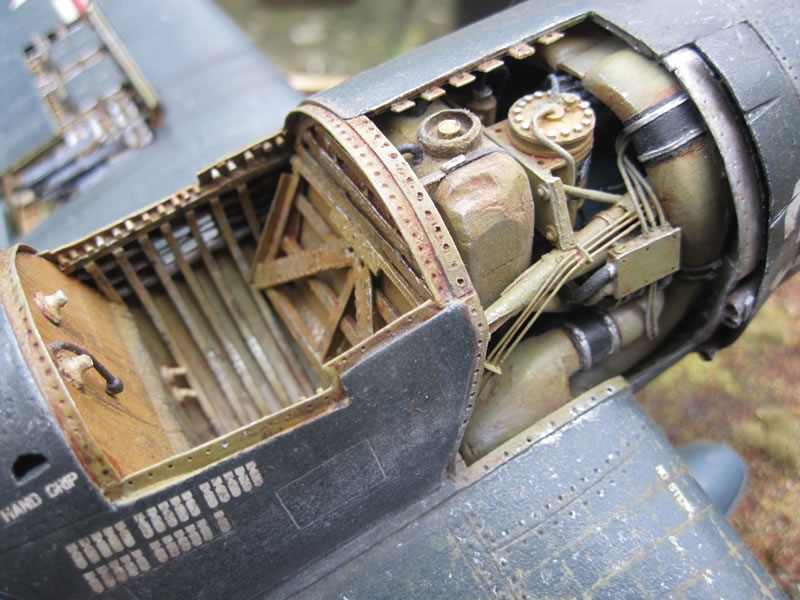
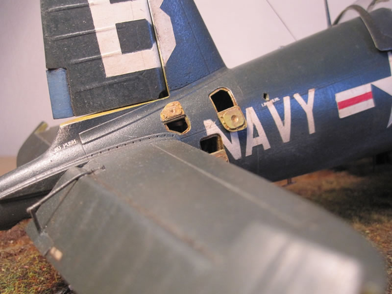
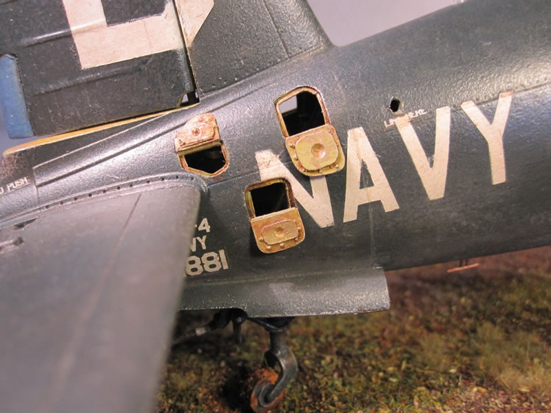
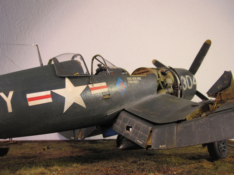
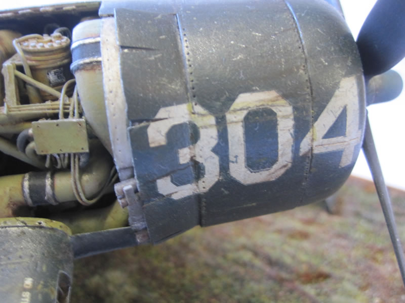
First things first - I had decided to display numerous panels open, so with a new blade and a scriber I carefully removed the fuel cell bay panel, the engine accessory compartment panel and an engine panel (picture 1). In order to retain some fuselage strength I only removed the port side engine panel, and the starboard accessory compartment panel. I also opened up the tail wheel access panels, cut out the starboard pilot's access step and hand grip near the windshield (I had a photo of a machine with it permanently open and figured the spring mechanism must have worn out, so I thought it would be a nice touch). This kit suffers from thick mouldings and dozens of prominent ejector pin marks - I filled them all and sanded everything that would be visible down to scale thickness with a sanding block. One of my abiding memories of this build will be the amount of filling and sanding!
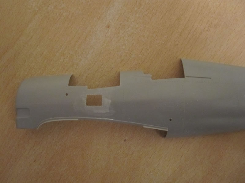
Picture 1
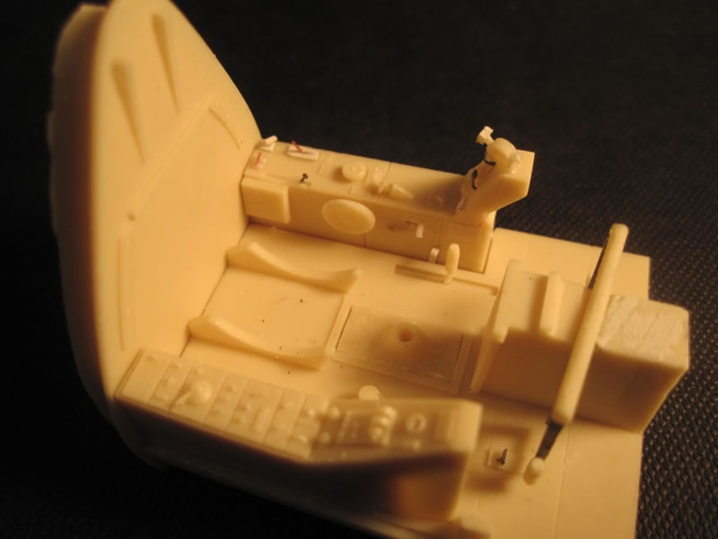
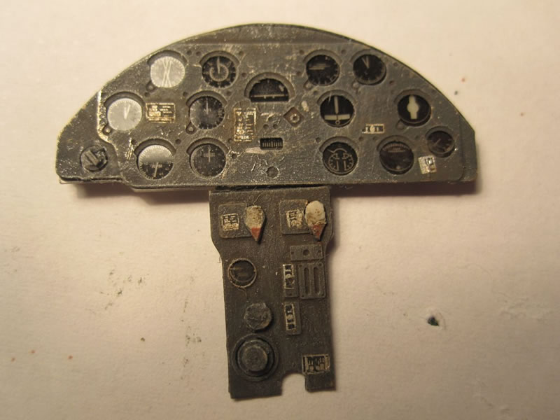
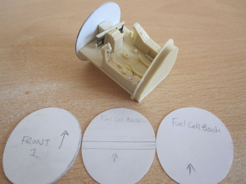
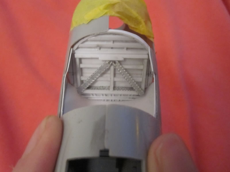
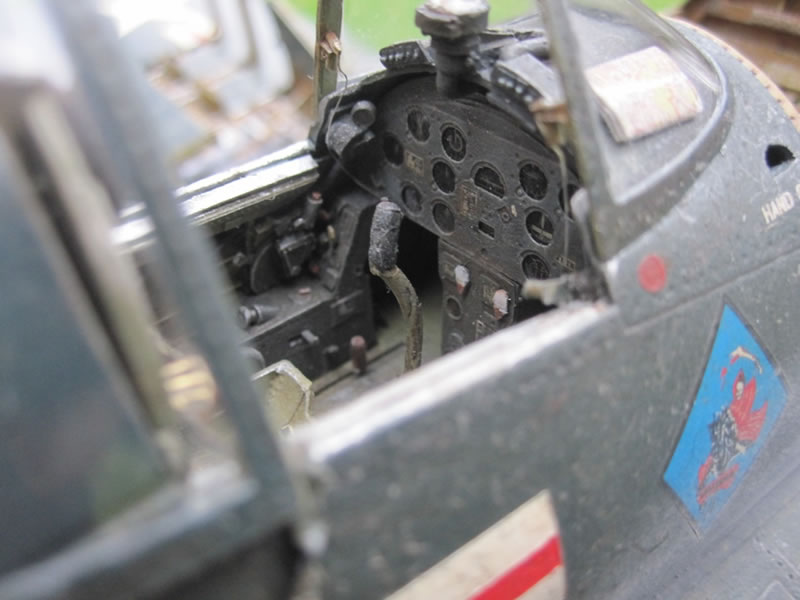
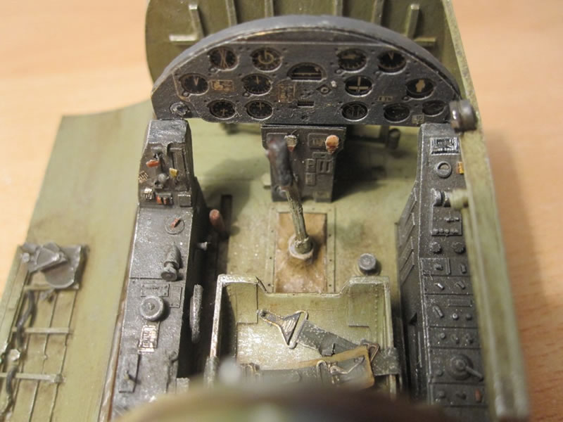
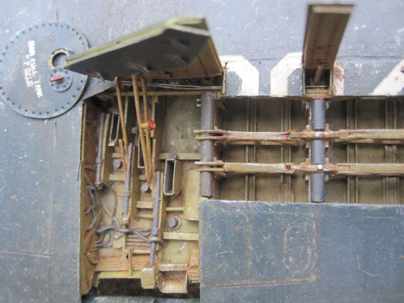
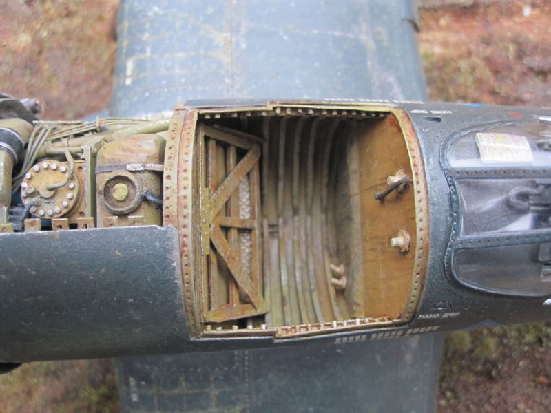
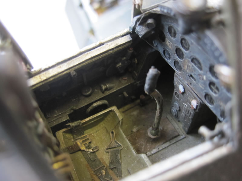
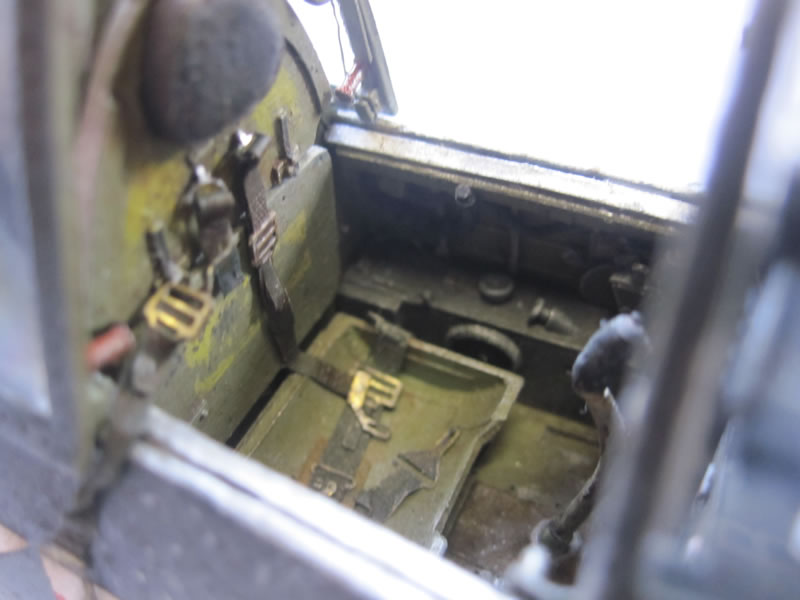
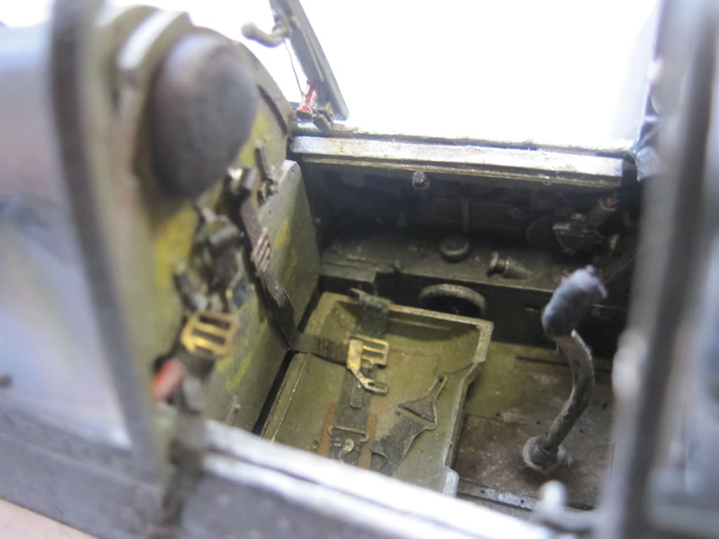
The Grand Phoenix cockpit is a nice set, and about 90% accurate - I added any missing details from plasticard, wire and anything else that came to hand. The instrument panel comes with the Grand Phoenix kit. Data stencils are from Mike Grant Decals. Rather than use the set's front cockpit tub panel, I used it as a template to create a piece that would serve both as the front panel and also the the back panel for the fuel cell bay. I then made a corresponding, slightly larger piece to serve as the fuel tank bay front panel/engine mount panel.
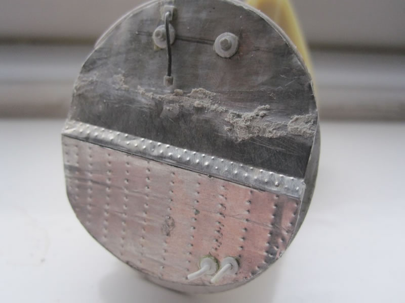
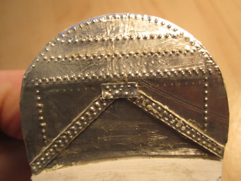
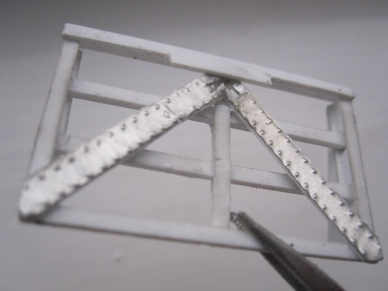
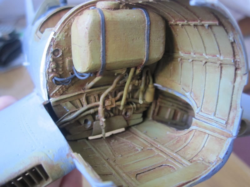
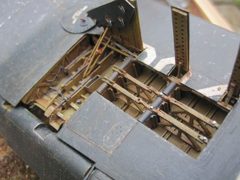
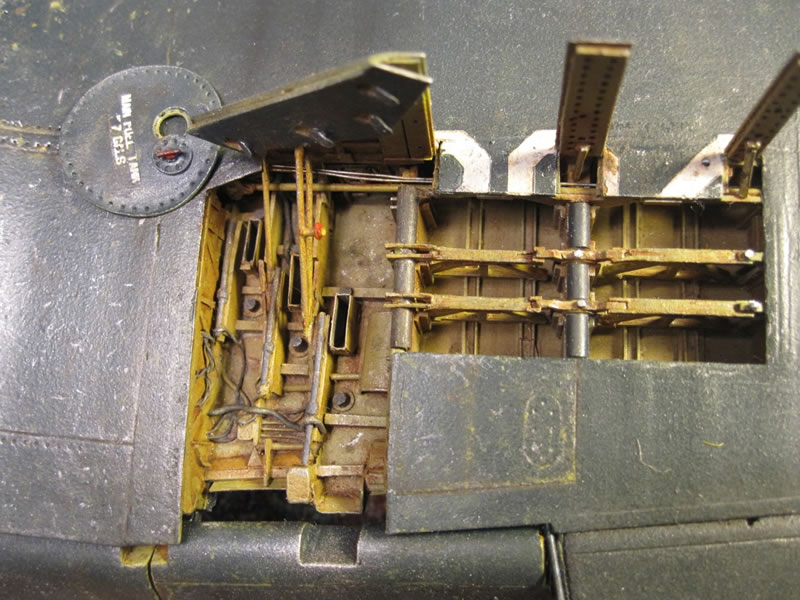
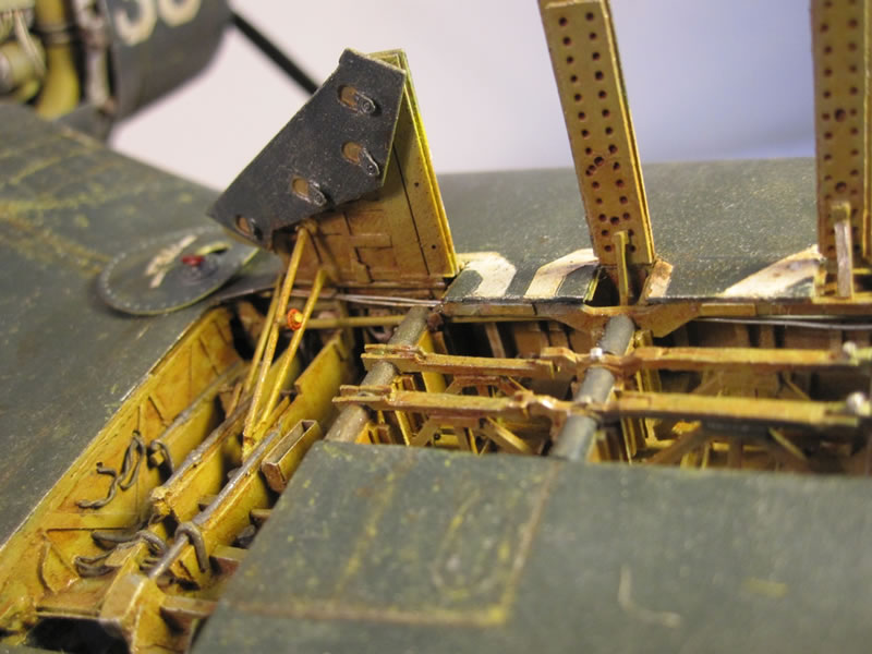
After that it was a case of using my reference pics and a ton of plastic sheet, strip and rod to replicate the fuel tank bay. The real thing shows lots of rivet detail, so for prominent bits I used thin sheets of aluminium from a takeaway carton, and a riveting tool. There is a little artistic licence involved as I used the Mk.1 eyeball, but the end result is about 95% accurate.
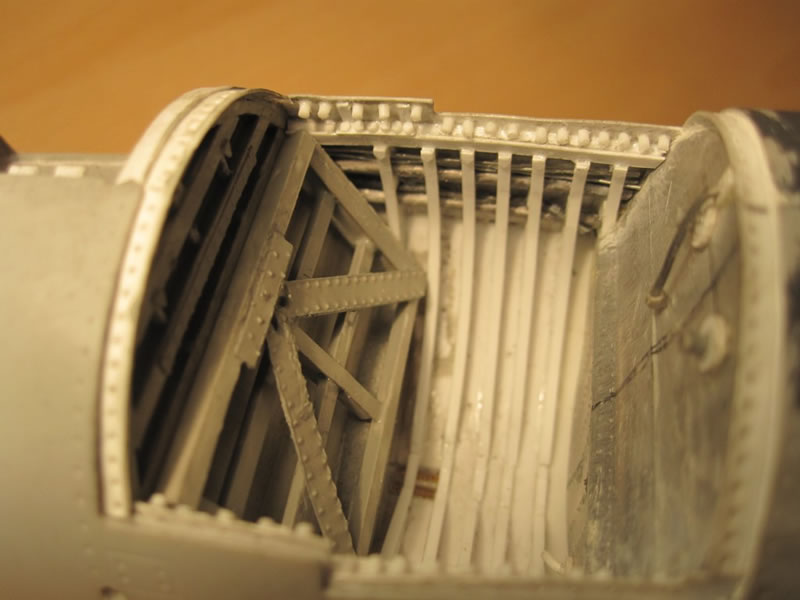
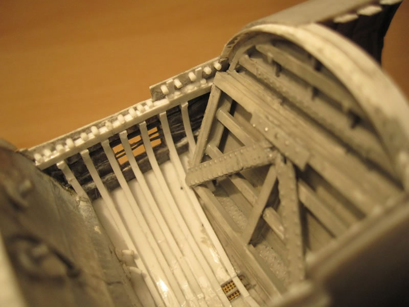
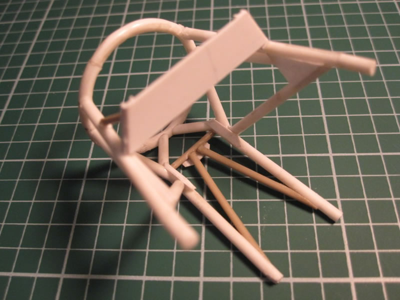
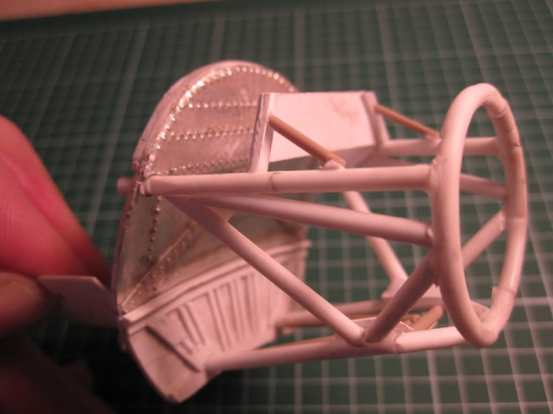
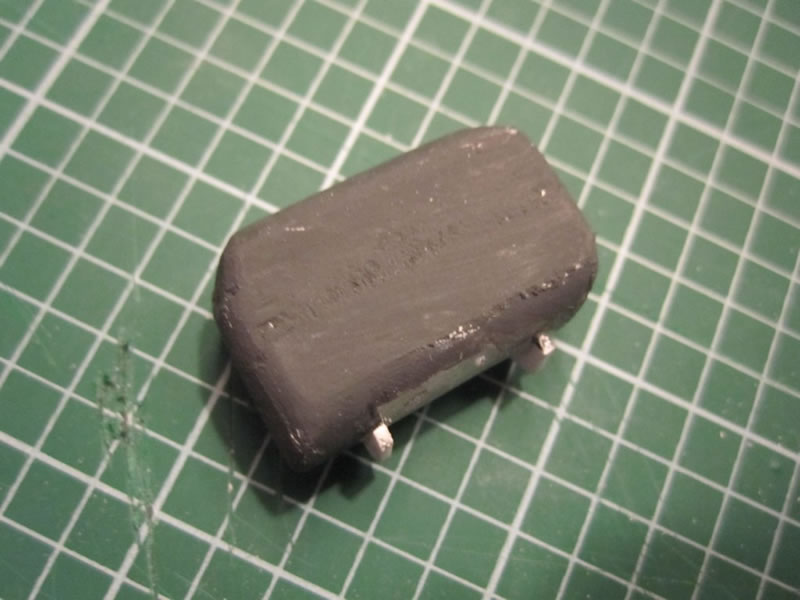
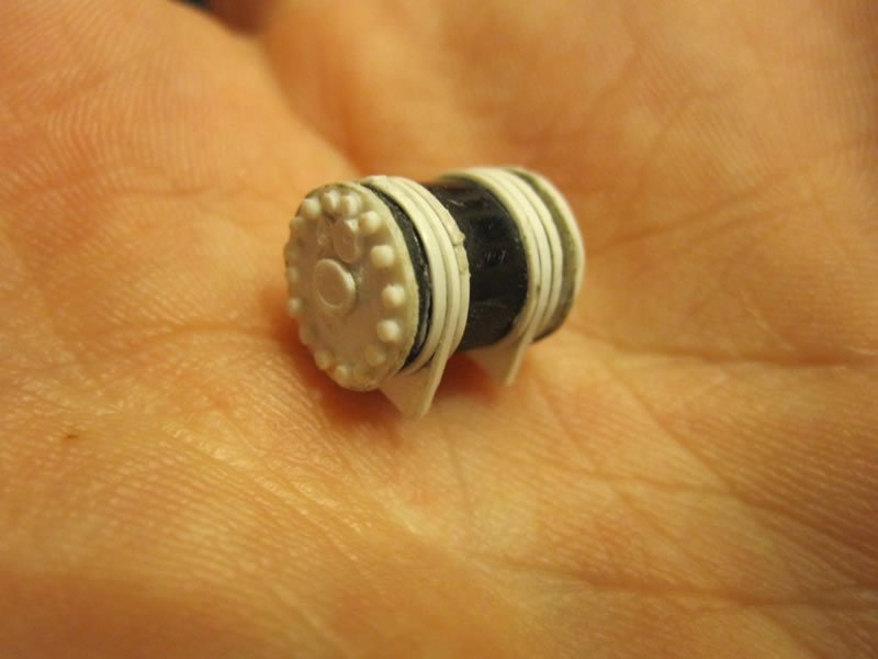
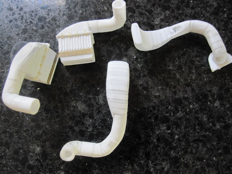
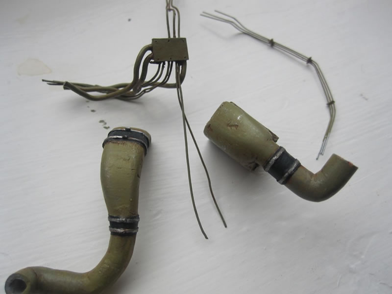
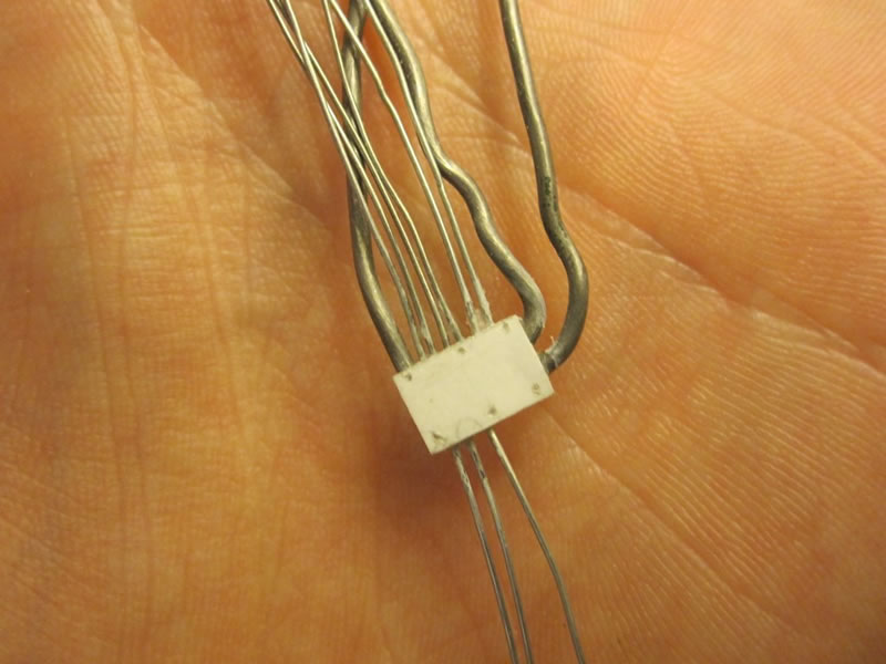
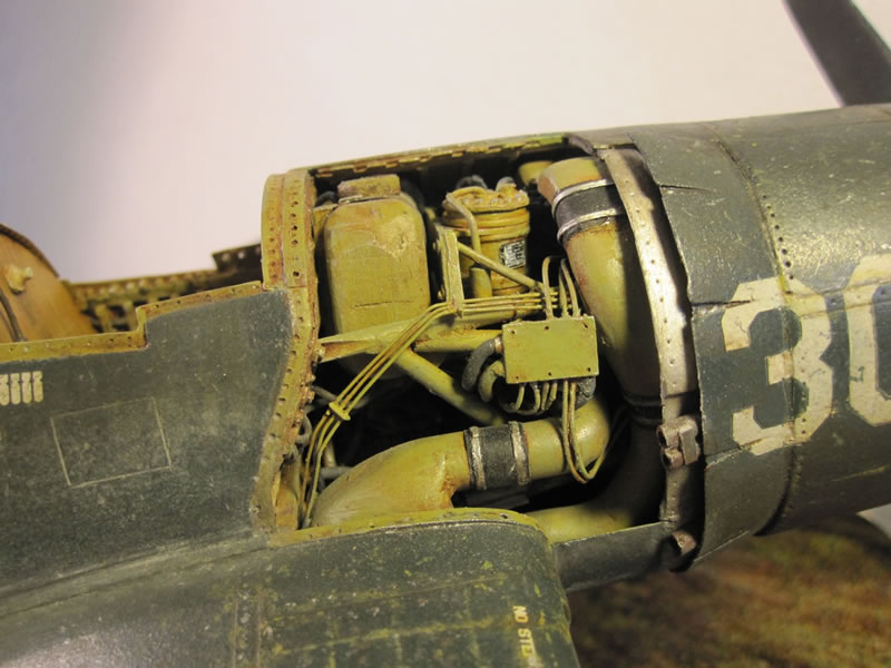
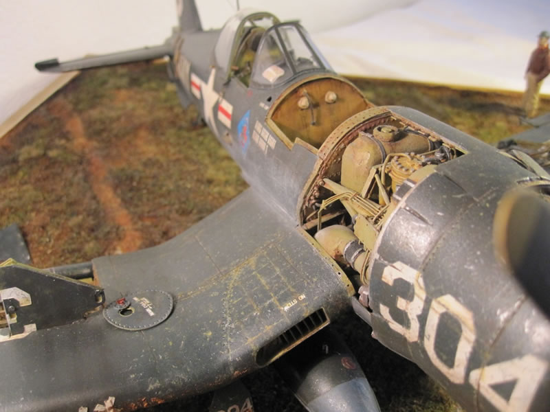
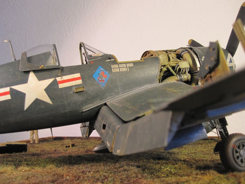
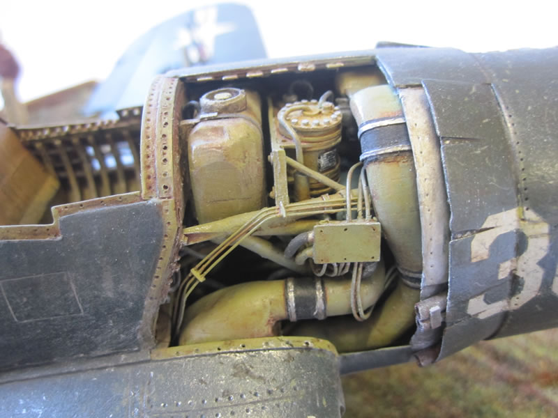
The accessory compartment was next. I built the engine mount through trial and error from appropriately scaled plastic rod. The round 'mount' part was made by gently heating some rod and curving it around the lid from a bottle of Micro-Sol, which was roughly the right diameter. I then sanded the end flat so as to have more of a surface area to attach the engine itself. The oil tank is made from half a dozen pieces of thick plastic sheet sandwiched between an X-acto knife handle, which had the right curves for a basic shape. The extra curves and dimples were made using Squadron green stuff and good old sanding. The hydraulic fluid reservoir started life as a section of the top from a propelling pencil, and various plastic sheet, strip and rod completed it. The pipes for the air cooling system were the most difficult to make - The bottom parts are basically box shapes made of plastic card. Then there is a round tube part. I then added wedges of plastic that gradually increased in size towards the top and curled inwards, and filled and sanded them smooth until the right curves were achieved - the top of the pipes are actually elliptical in shape and have quite a severe notch sanded out of them on the inside so they fit around the frame of the engine mount. To finish off, I added the prominent junction box and wiring from plastic scrap, with a mixture of fuse wire and spare wire I stripped out of some electrical wiring. I had some spare Verlinden 1/35 nuts and bolts which I used to dress things up around the engine mount. Once everything was crammed in it was extremely difficult to glue everything in place, which is why literally hundreds of dry-fits were required as I went along.
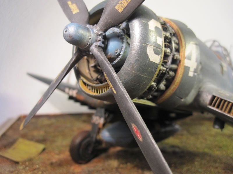
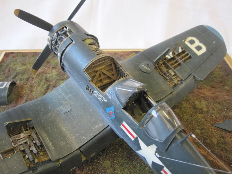
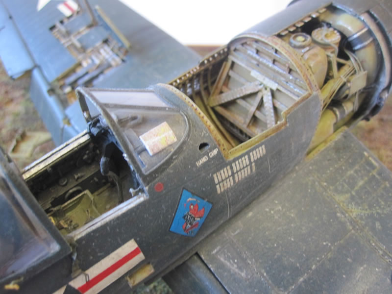
Next was the engine - the kit provided engine has a lot of parts, but it is quite crude, especially compared to the fantastic resin replacement I used from Vector models. In my experience these engines are the best available, and are little kits in themselves. It is very important to paint every part before assembly as it is impossible to do so afterwards. To give added strength, I drilled small holes and added small pieces of guide wire to each part, for example each cylinder to the cylinder block. This also helped with aligning each part and making sure it was exactly in the right place. The ignition wires were made from fuse wire. I added interior rib detail to the cowling panels where I thought it would be visible using thin plastic strip (picture 25).
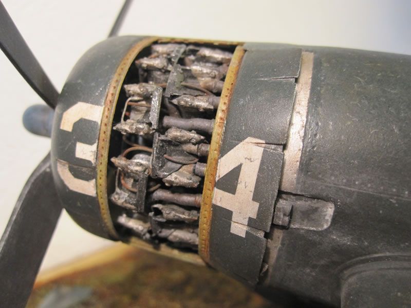
Picture 25
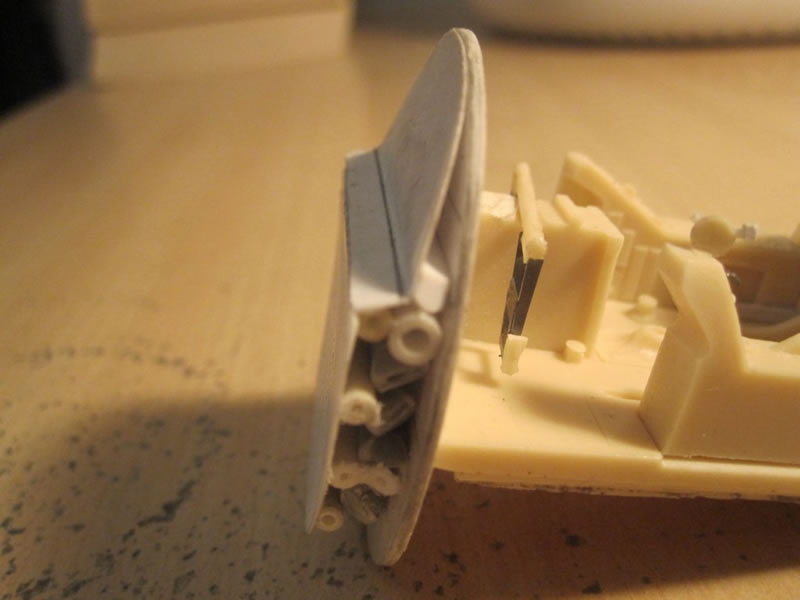
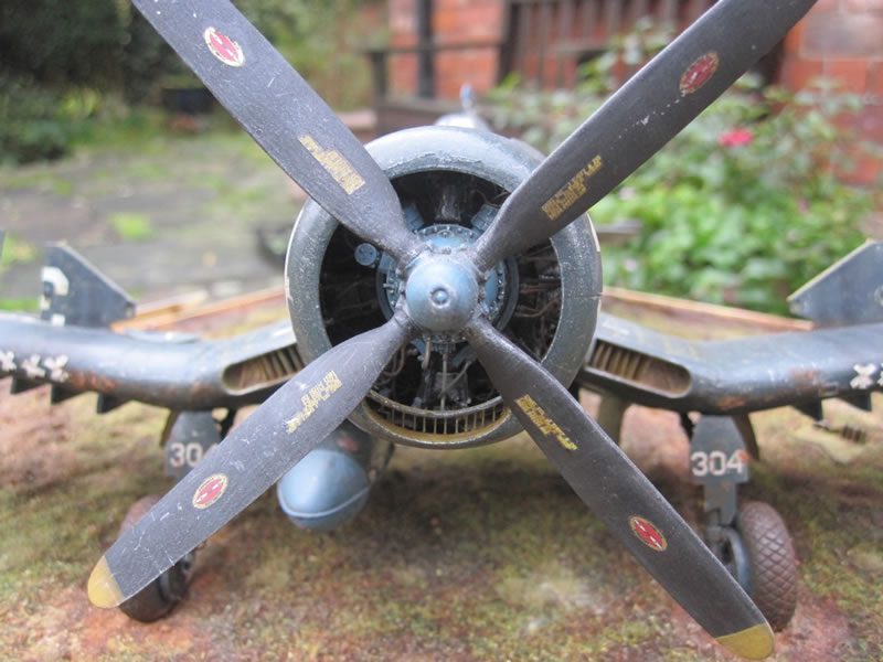
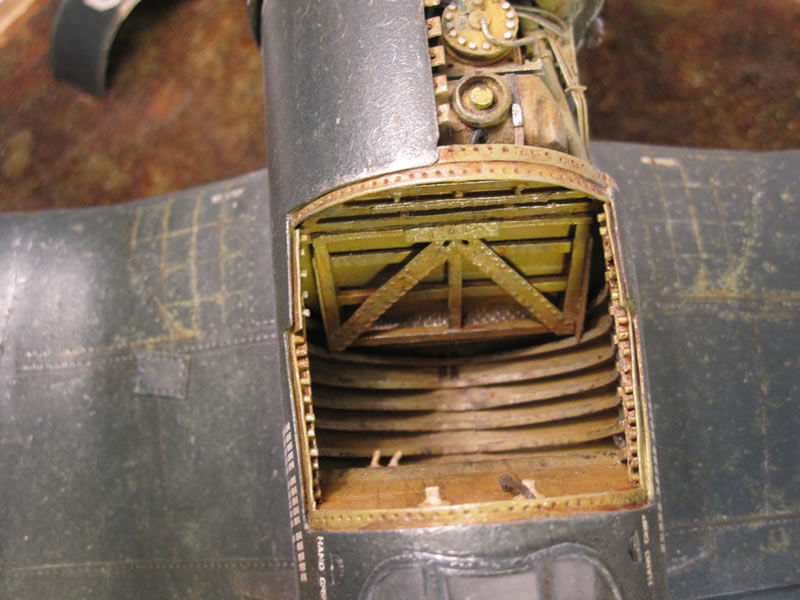
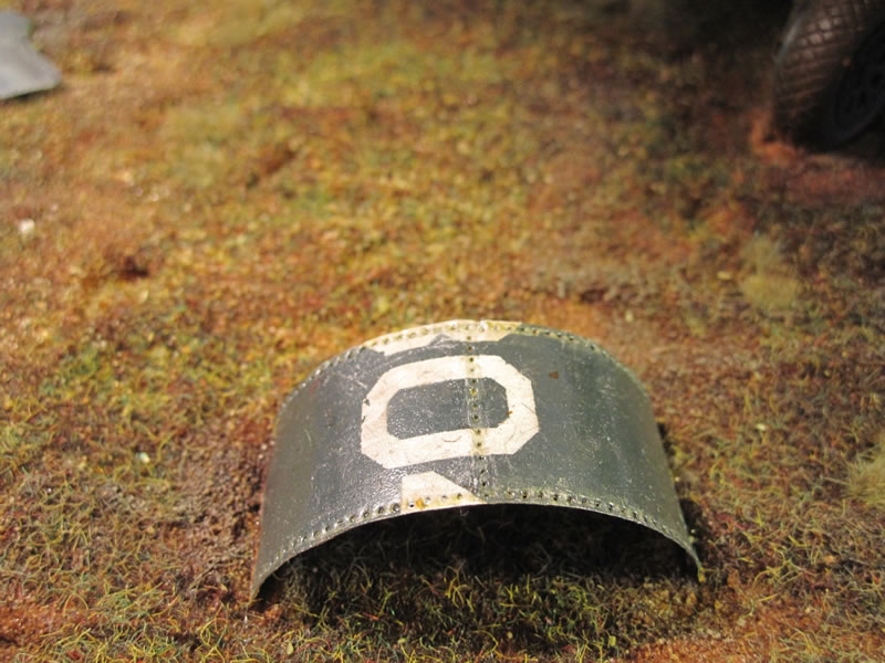
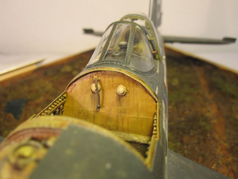
The front cowling in the kit doesn't have any of the interior depth, curve and detail of the real thing. I remedied this by cutting a ping-pong ball in half and gluing it to the inside of the removed cowling. I filled the void between the two parts with plastic scrap and bedded everything in with Milliput. Once dry, I removed the excess and sanded flat. The grill in the air intake 'mouth' was added from small pieces of wire. (picture 26)
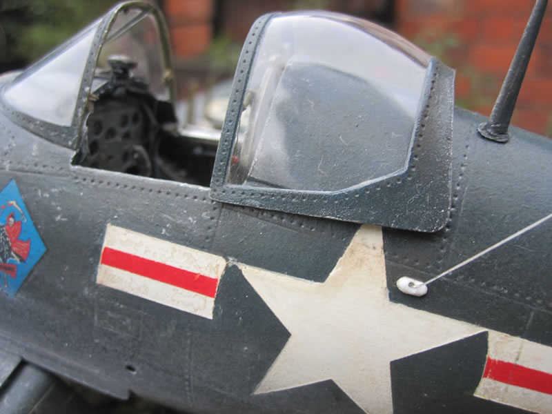
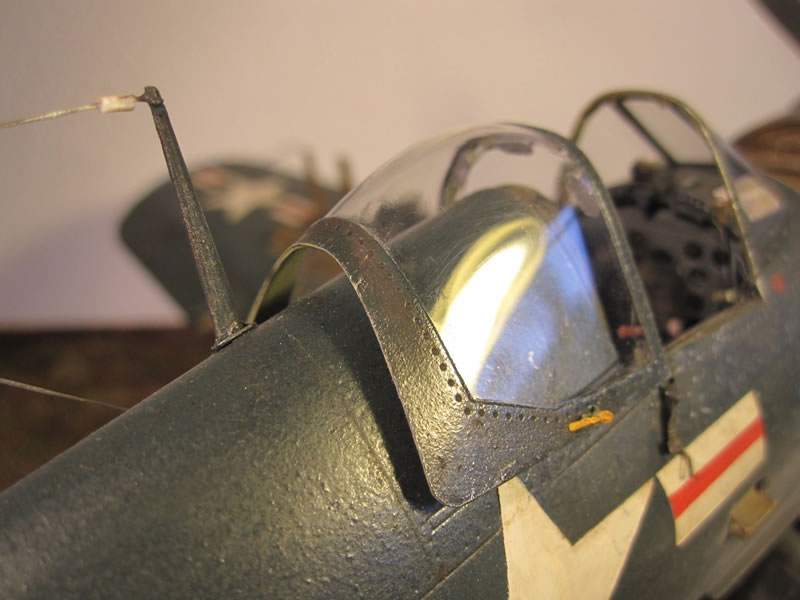
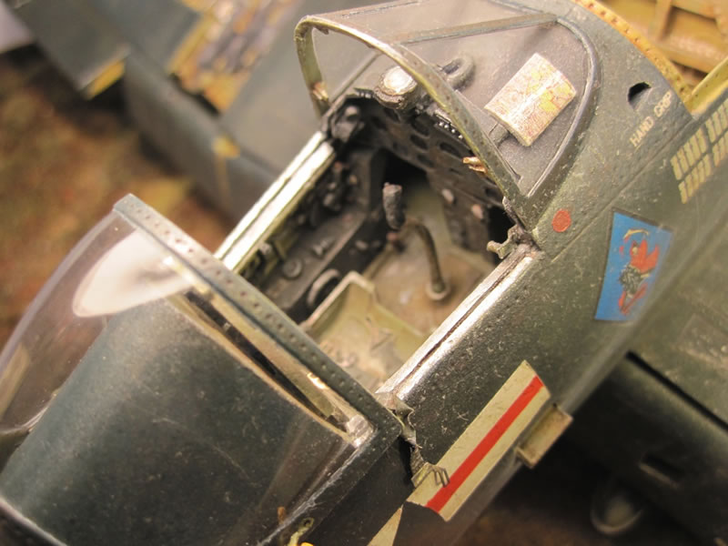
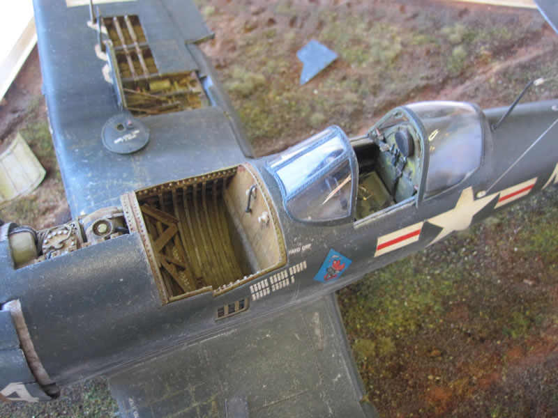
Next up was the canopy - I had some good shots of the framework from the Modeller's Datafile book & off the net, so I had a go at replicating the locking handle, emergency release handles and rear view mirrors from plasticard - I also added the tension / wire system that locks the canopy down once it is closed using thin gauge wire from some electrical cabling (picture 27).
Picture 27
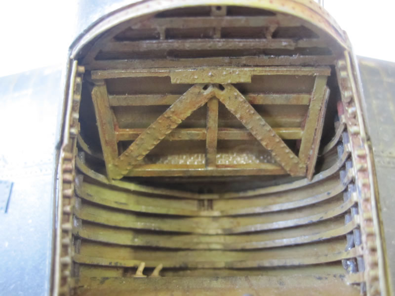
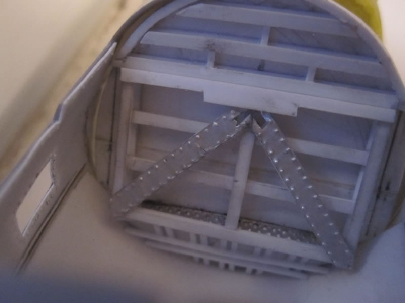
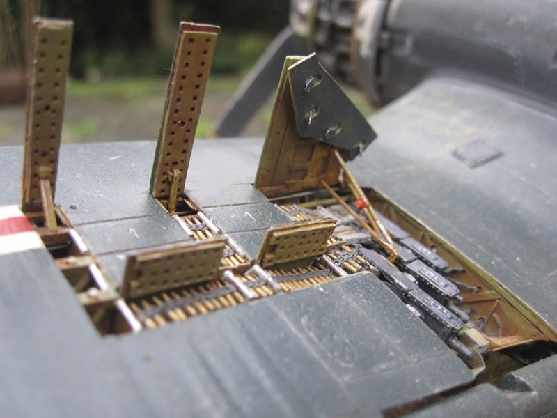
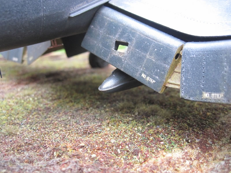
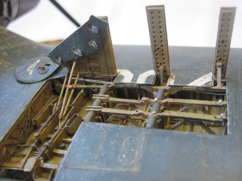
Finally for the fuselage section, I built a complete tail wheel well. Sadly it is mostly hidden on the completed build, but I know it is there. I relied heavily on my online sources for this part and I am confident that I've created the most complete wheel well yet on a Corsair build - shame you can't really see it! I used almost exclusively plastic sheet, strip and rod. The elevator control wires running back to the cockpit are again fuse wire of an appropriate diameter. (pictures 28-33)
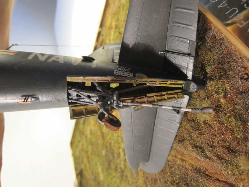
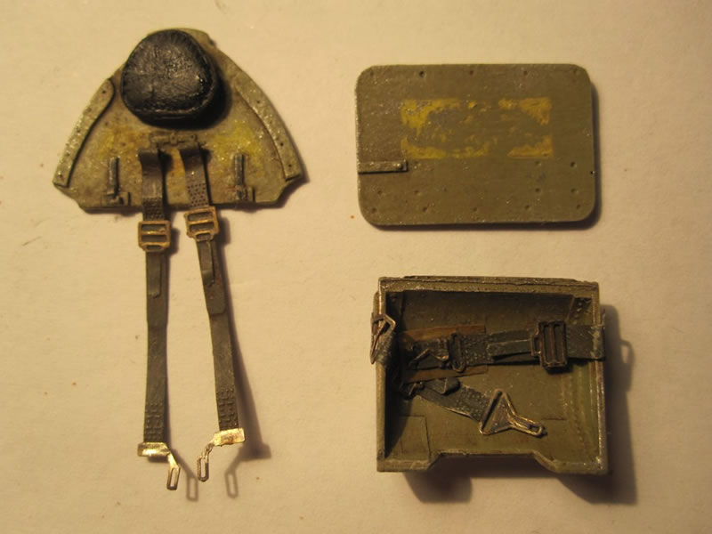
I painted everything inside the fuselage and the cockpit using Humbrol enamels, various washes using oils, and drybrushing and weathering using pigments and enamels. The map inside the windshield is from an old Verlinden set. The seat harness comes with the Grand Phoenix set & is very nicely detailed - I decided to have one strap hanging out of the cockpit as though the pilot had struggled to extricate himself. I've seen this done on other builds and it helps to add life to a model.
Finally I used Jerry Rutman's nice resin Hamilton Standard prop and hub, which are a definite improvement over the kit parts with a more realistic chord and shape.
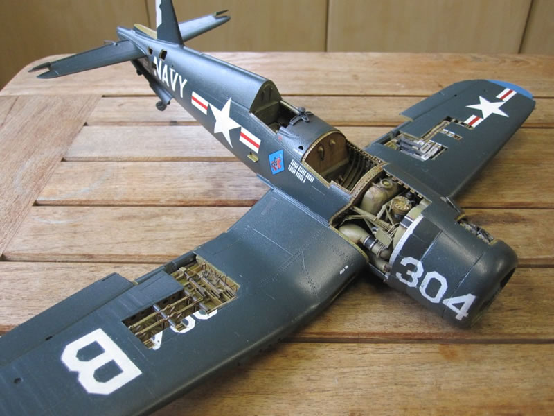
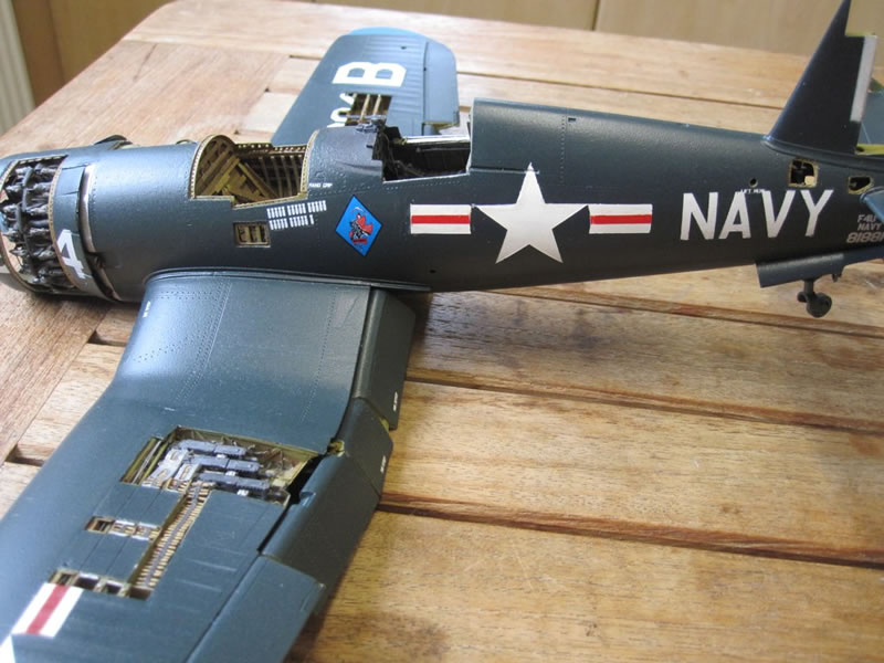
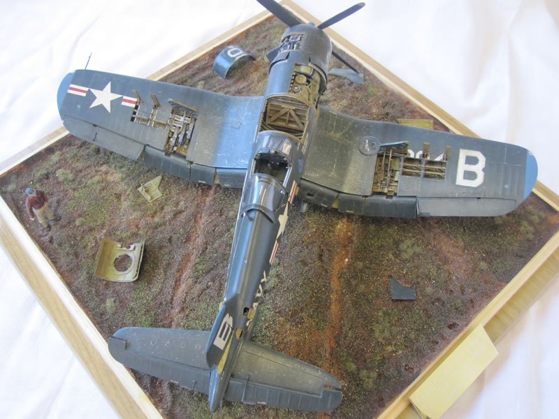
Wings
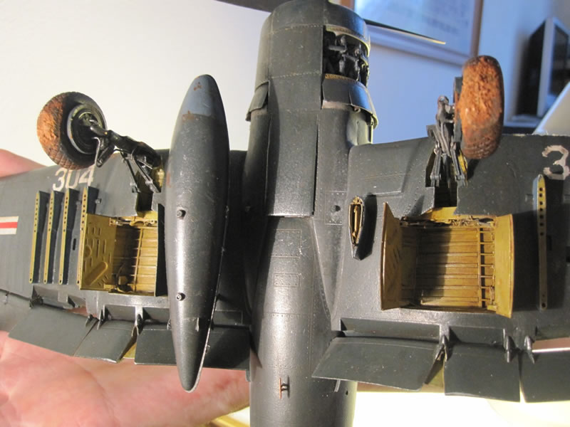
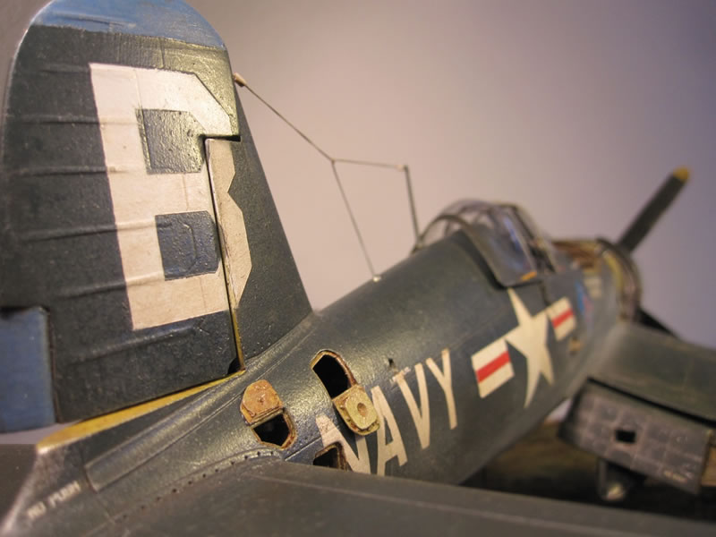
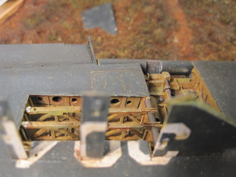
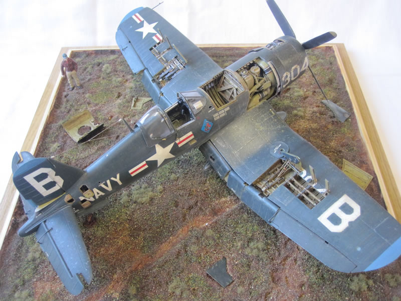
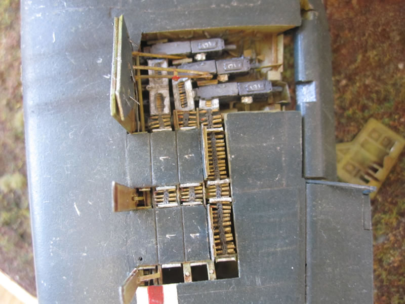
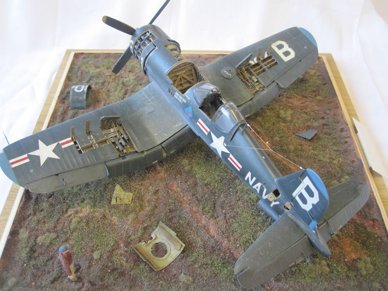
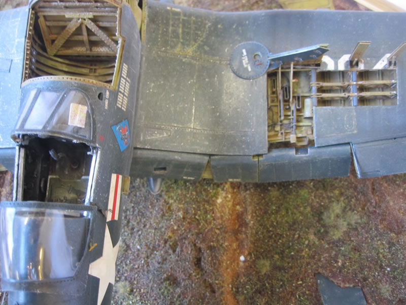
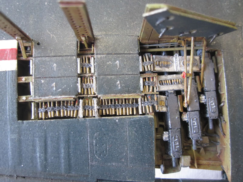
I decided from the off that I wanted to display the gunbays open. Again the kit provides this option, but the detail is crude. I bought the Aires replacement gunbay set and after checking my sources I again realized that there was a whole lot more I could add. The bays themselves are relatively good, but I decided to remove the ammo trays. I scratched the port side ammo boxes/trays/lids from plastic card, completely replacing the Aires parts. I then added individual .50 cal rounds and links from Mission Models, quite possibly the most fiddly thing I have ever done modelling-wise. After 15 hours work, I had some belts of ammo that looked so much better than anything else available, exact replicas of the real thing. The .50 cal gun bodies are from the Aires kit, the barrels are brass replacements from RB Productions. The feed chutes are a composite of Aires parts from both the port and starboard sides. As I didn't use the starboard chutes, I could make some truly 3D versions for the port side.
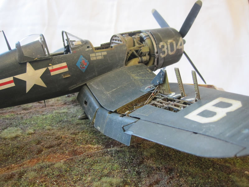
I depicted the starboard bay as empty. After again removing the shell trays with a razor saw I scratchbuilt everything that I could see in my reference pictures using plastic sheet, strip and rod, fuse wire and also thin aluminium sheet, including wing spars, wing fold actuating rod, spent shell chutes, the control arms holding the doors open and control wires.
To finish off, I added numerous details to the 'bay' parts of the Aires set and fitted everything into the wings using a mixture of liquid cement and ca glue. The kit is engineered so that you can display the wings folded. Unfortunately if you don't do this (and bearing in mind I had a load of other stuff crammed in there) the wings are structurally very weak. To add strength, I made some spars out of brass sheet, doubled them up for each wing, and secured them firmly with superglue. A lot of filler and heavy sanding fitted the outer and inner wing pieces together permanently.
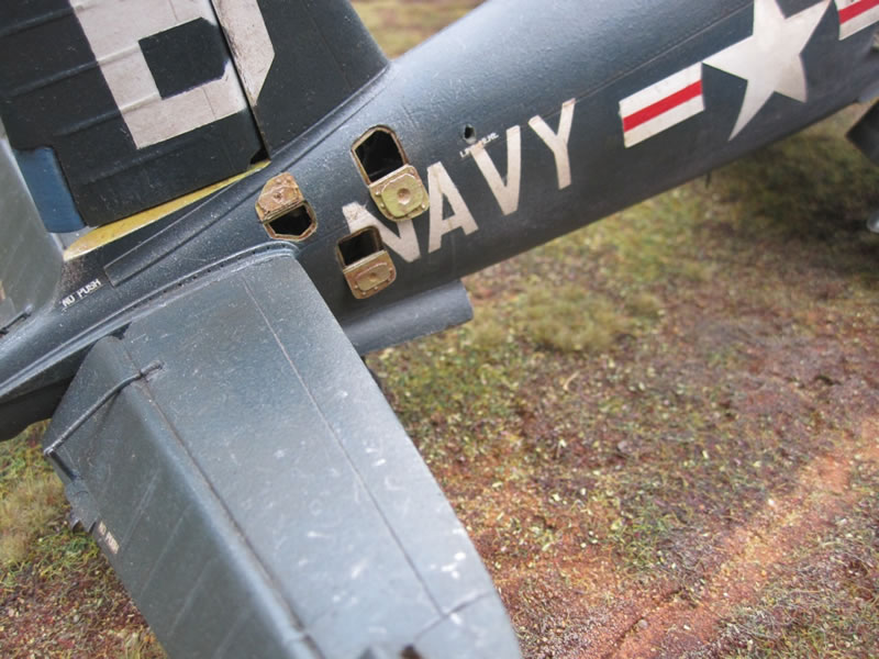
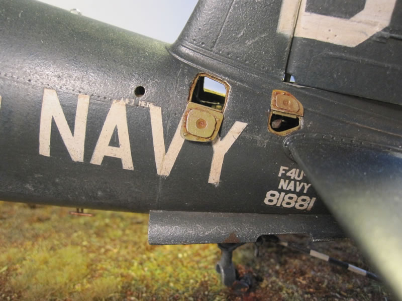
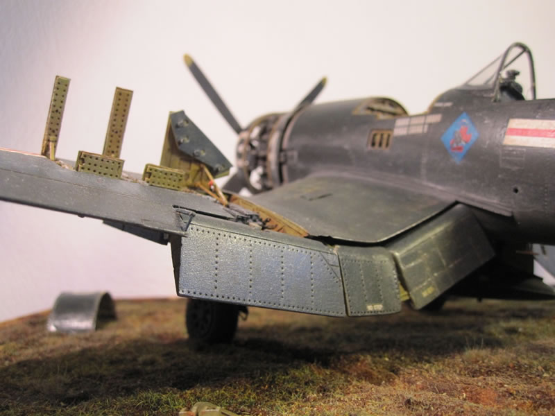
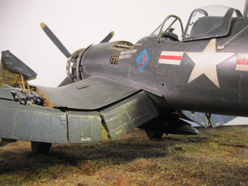
Next up were the oil cooler intakes - the kit parts are crude, so I removed the 'vanes' and replaced them with thin strips of plastic sheet. The oil coolers themselves are sections of a ballpoint pen that was roughly the correct diameter, with etched brass mesh from the spares box (picture 45). I did add some of the piping and wire detail behind them, but it is hardly visible on the finished model.
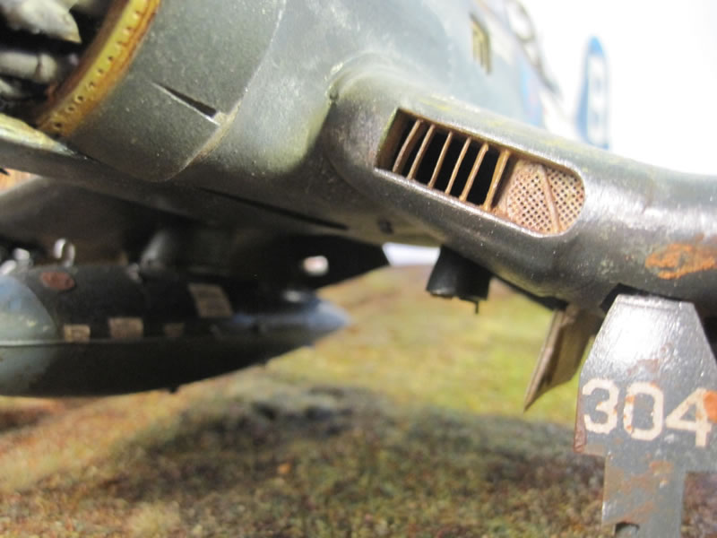
Picture 45
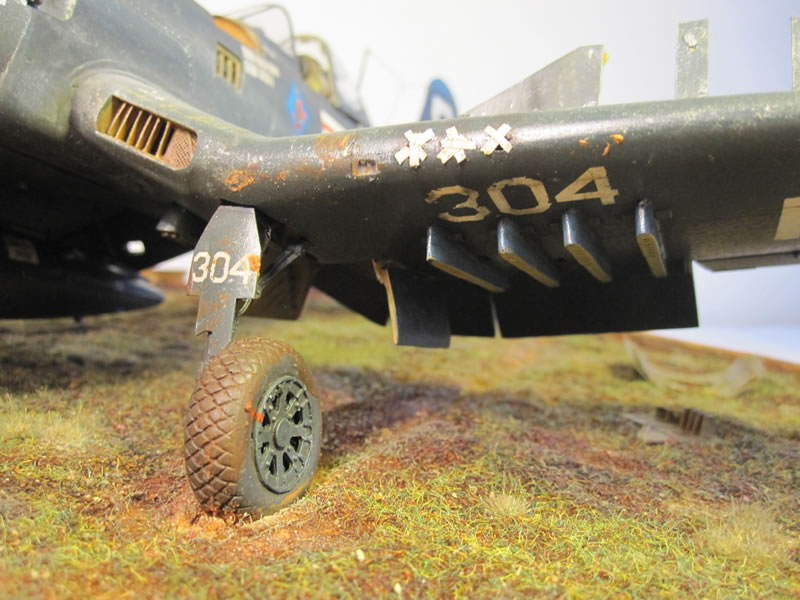
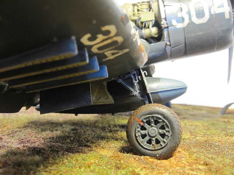
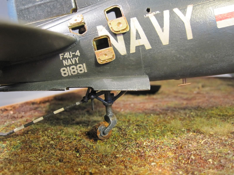
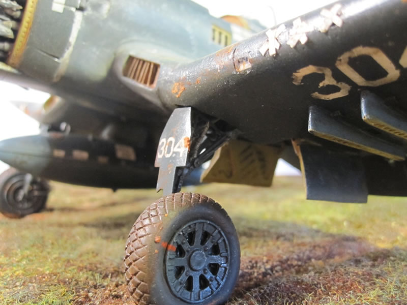
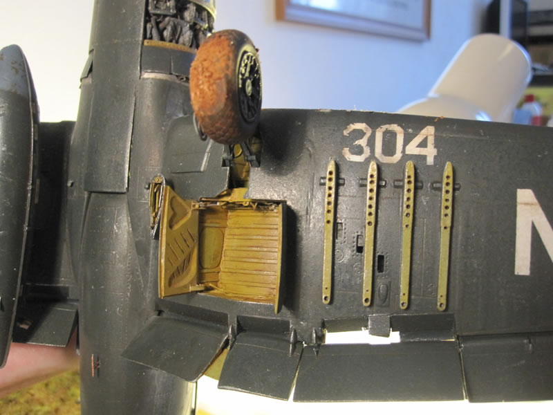
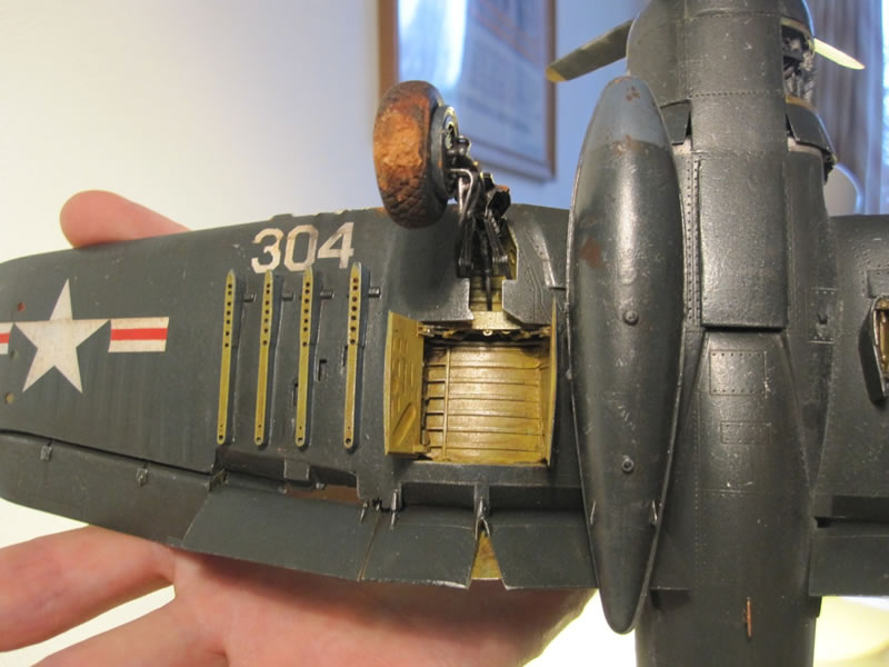
The wheel wells are again from Aires. The fit is very poor, and heavy sanding is required. In the end they just about squeezed in with a ton of superglue. They are about 95% accurate, so I added very little further detail save a few wires. I scratchbuilt the landing gear from plastic tube, strip, rod and some of the photoetched Aires parts. As the tube I used for the main undercarriage legs was hollow, I was able to insert a steel rod in each for added strength. Even so, I managed to snap the port wheel off the finished build! I would recommend anyone building one of these large aircraft to use a replacement undercarriage leg set from a company such as G-Factor or Scale Aircraft Conversions because large, finished models like this are heavy. The tires in the kit are the dubious 'rubber' type that I really dislike - they were replaced with weighted resin ones from Jerry Rutman (picture 46).
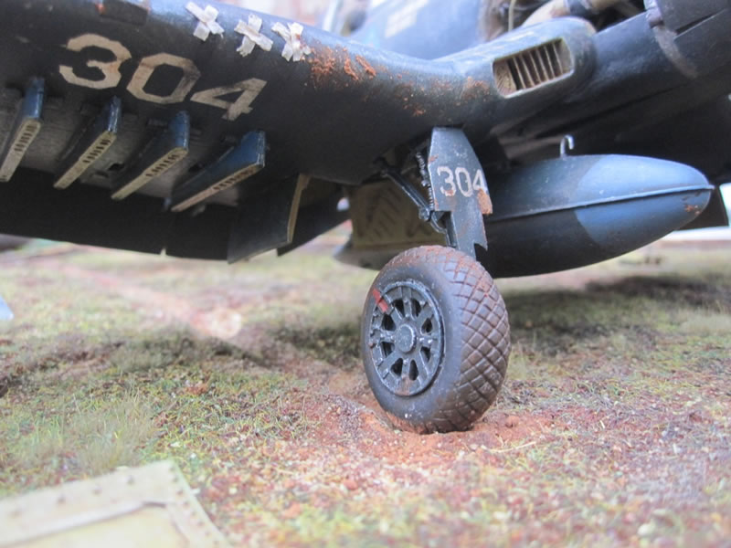
Picture 46
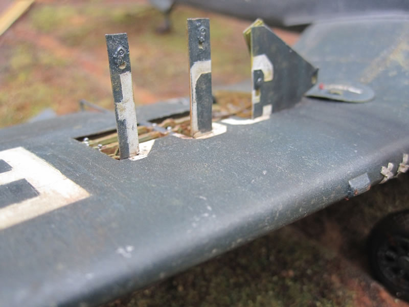
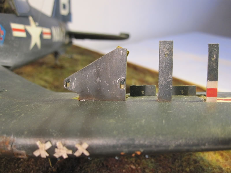
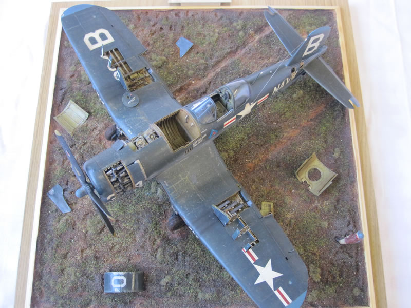
I wasn't happy with the way that Trumpeter did the ribs that show through in the (wood/fabric) tail surfaces and rudder - the effect was far too heavy. I sanded the lot off & started again with thin plastic strip - the trick is to sand away the ends and sides to blend them in. I added some 'movement' to the trim/balance tabs by removing and re-positioning them (picture 47).

Picture 47
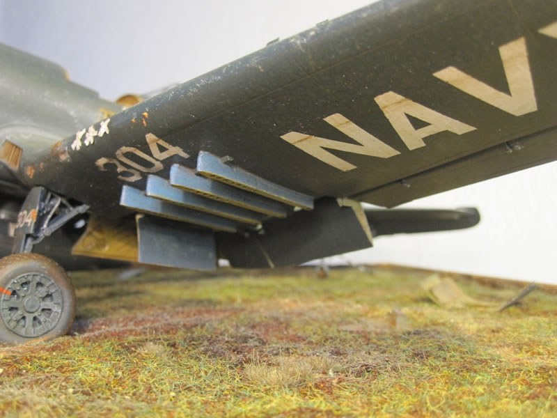
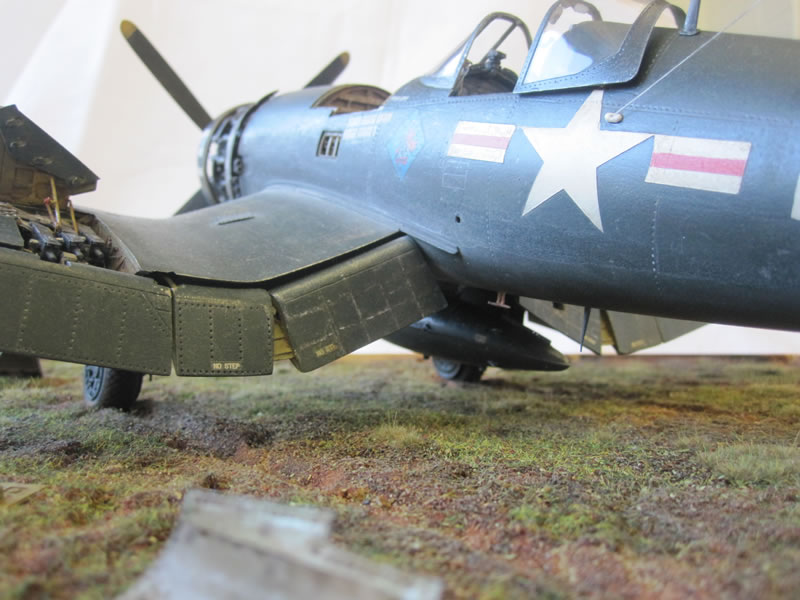
I scratchbuilt the underwing universal weapons pylons. The kit provides only zero length rocket launchers. I planned to show the model without any ordnance, and my reference pics showed that these universal racks were often employed. I used plastic strip and sheet, gradually sanding in the 'curve' I needed to mount them snugly to the underside of the wings.
I decided to just have the one mounted tank. Reference pics show these tanks as having a lot of data stencils - I replicated this by painting the appropriate areas white, then applying old 1/72 data decals from an F4 Phantom data sheet. The whole thing was given a sludge wash of raw umber oils and weathered - I figured out that as the pylons were 'wet' ie plumbed internally, then the funny little thing I could (just) see on my ref pics must be a sway brace. Trumpeter provides one but it is very crude, so I made my own out of oval shaped plastic rod. The other fuel tank mount was hollowed out, and an approximation of the internal structure and fuel line was created with plastic card and more fuse wire.
Final details on the wings were the flaps. The Trumpeter kit is an early release, and consequently suffers from over-engineered parts. I kept the kit's system of metal hinges but just glued everything in place securely with ca glue rather than have the flaps as 'moveable'. I cut out the pilot's step in the starboard inboard flap. It is important to note if you are building a Corsair that this was a post-World War II innovation and appeared on the dash-4 model onwards only! I spiced up the flap ends with extra details, and replaced the kit 'flap gap fillers' on the inboard flaps with thin plastic card detail.
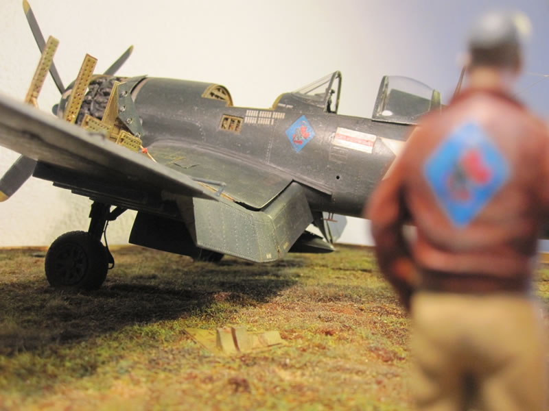
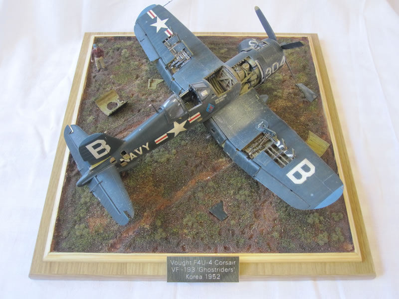
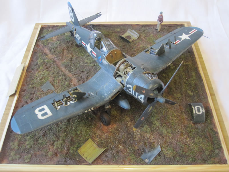
Base
I always intended to display the aircraft in its natural surroundings, so I firstly went down to the local timber yard to get a base (a cupboard door panel) and some edging strip - total cost £2.00! I made a nice border for the groundwork, then gave the whole thing 3 coats of gloss varnish - this seals any gaps and prevents any warpage at a later date. I then used the time-honoured method of creating groundwork - polyfilla. I coloured it with Windsor & Newton burnt umber acrylics, mixing the concoction until it looked like chocolate cake mix. I added fine sand bought at my local pet shop and spread the whole lot on the base. After 72 hours drying time I mixed up some white glue, water and more acrylic paint, painted it on and added Verlinden static grass, and grass clumps from German company Fredericus Rex. Before the groundwork dried I pressed in any items that would require scale weight so they would sit naturally. It's important to remember that groundwork is a scale item too, so weathering is required. I added a wash and drybrushed everything to bring out the highlights.
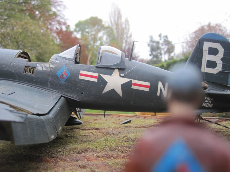
I've seen lots of pictures of aircraft parked up on muddy Korean airfields, so I was happy with the result. In case you are wondering what a Navy machine is doing at an airbase, it was common for them to land at forward bases to be serviced, or simply if the weather was bad, before returning to their home ship.
I wanted to make a pilot or mechanic - I settled on the former. I scrounged various bits from the spares box like a latter day Frankenstein. Legs and left arm are from CMK 'US Truck Crew' set. This figure comes with trousers bloused over boots with gaiters - I needed unbloused trousers and standard boots, so I chopped off the lower legs and replaced them with some from an old Verlinden mechanic figure. The body comes from the Jaguar 'US Flying Tigers Pilot' figure as it has the A2 flying jacket common with aircrew in Korea. The right arm is again from the spares box, beefed up with Milliput. Head is from Hornet, baseball cap again from another spare head. I also added a silk scarf from lead foil. Also added the belt buckle and flies from plastic card. Flesh areas painted with oils, uniform with enamels, leather jacket initially painted a browny colour with enamels then finished with burnt sienna oils. Squadron emblem on back of jacket is again a custom decal from my Ad Astra set.
Final Details
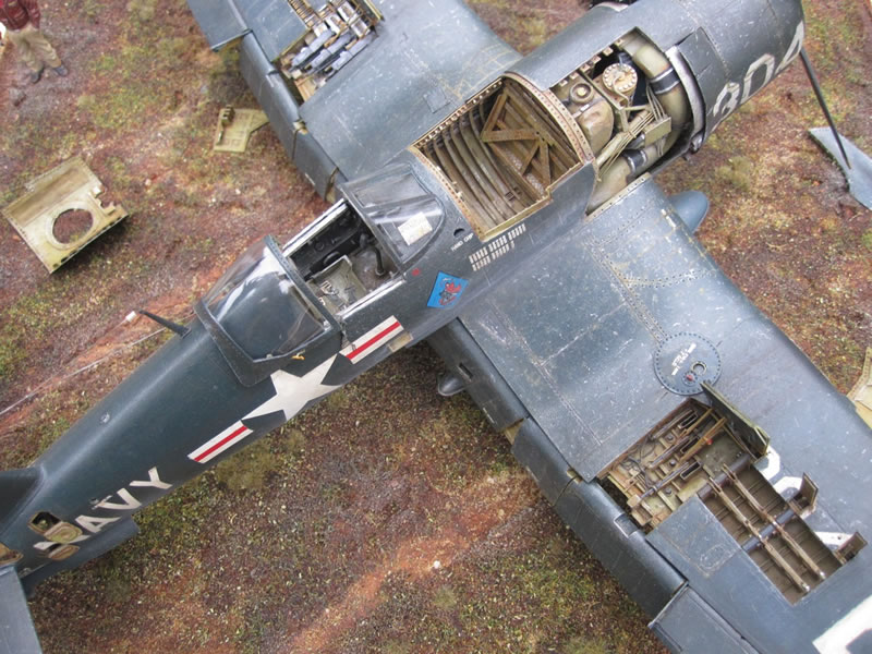
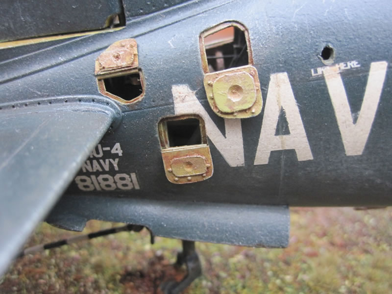
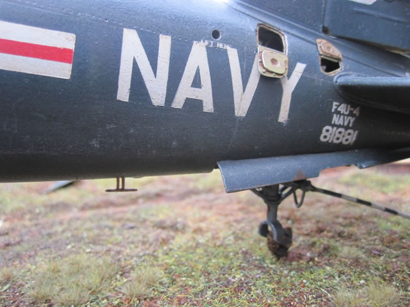
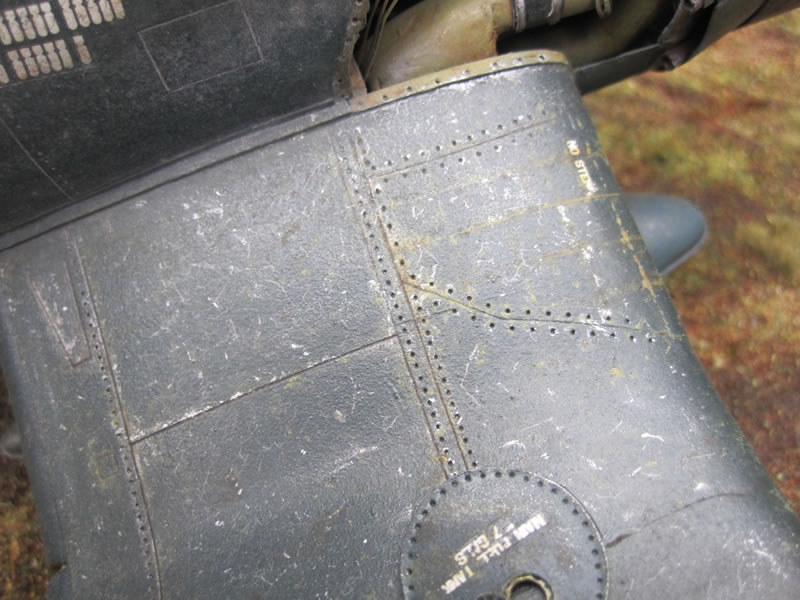
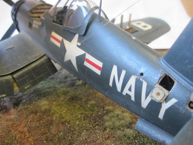
I tried to make this model stand out with little details. The canopy opening handle is a nice splash of colour, made from a tiny piece of plastic card. I carefully drilled out the corresponding recess in the side of the canopy frame. All of the various removed panels were created using thin metal foil from takeaway cartons, with rivet detail added using a riveting tool to mark the rivets out and then a bradawl to punch through. Plastic strip ribbing finished them off. A new pitot tube was made using plastic rod. The actuator arms for all of the flaps and ailerons were made using thin wire or plastic. The pilot's drop down step was added from plastic card, and the little actuator rod from brass wire. I taped over each gunport, as was common practice among ground crews to prevent dirt and debris entering the guns on takeoff - to replicate this, I stuck some Tamiya masking tape to my workbench and painted it white. After drying, I cut it into thin strips and taped over the ports. I roughed up the end of each piece as though it had been roughly torn from a roll of tape. The gun blowback streaks and the engine exhaust stains were created with Mig weathering powders and artists pastels.
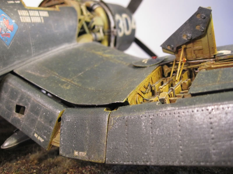
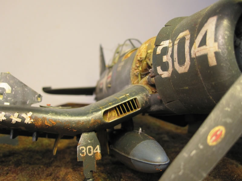
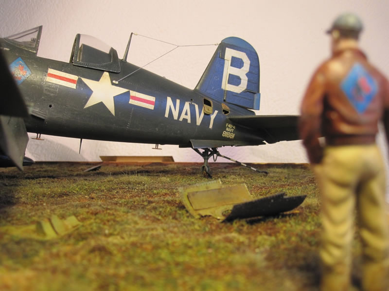
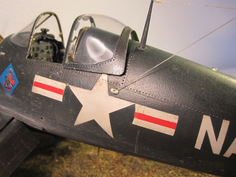
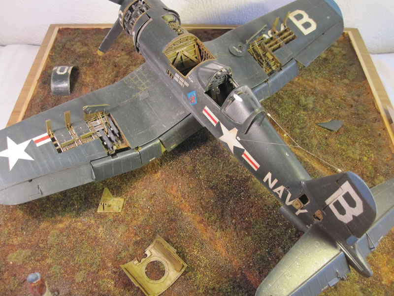
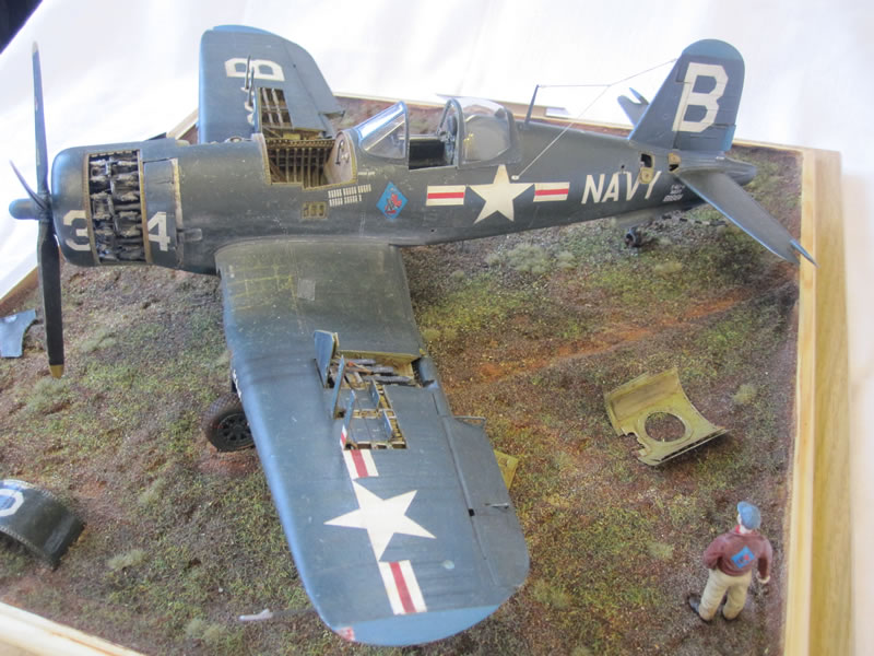
I painted the entire model with my Iwata airbrush and Xtracolour glossy sea blue paint. As I used to be an armour modeller, I weathered using oil washes, pastels, pencil chips, filtering - everything and anything I thought would enhance the finish. Although this kind of finishing on aircraft builds is not to everyone's taste, these Korean War birds got really filthy in combat and I wanted to show this on my model. I based the weathering heavily on images of KD-431, the Fleet Air Arm Museum's Corsair, which has been painstakingly restored and shows the original WWII finish - and weathering patterns.
All markings are custom made by Ad Astra and are a mixture of masks and custom decals to my specifications. Aircraft depicted is from VF-193 'Ghostriders' based on USS Princeton in 1952. This particular machine was lost to AAA fire in late 1952 and the pilot K.I.A.
Conclusions
I hope you've enjoyed my build. I certainly enjoyed researching this distinctive and magnificent plane. There are some areas I'm not 100% happy with. However, overall I feel content that the model is 'finished'. I entered the model in competition at the IPMS UK Championships at Telford last weekend - my first competition entry since 1994. I was lucky enough to get a 'commended' for my efforts, and the recognition made all the hours worthwhile.


© Rich Carrick, November 2011
This article was published on Wednesday, January 25 2012; Last modified on Saturday, May 14 2016