
Airfix 1/24 Fw 190D-9 Part 2
By Rodney Williams
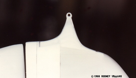
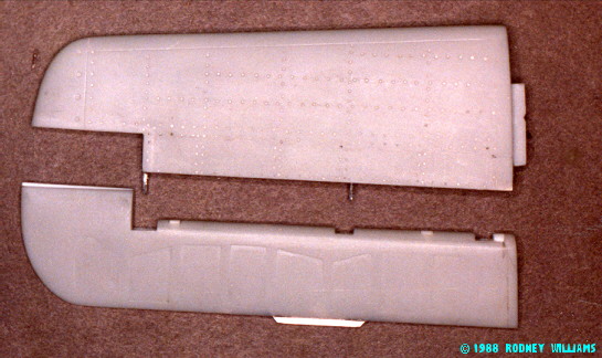
The enclosed four photos show the "tail plane". I had to add an extension to the fin section, using sheet styrene. It's crazy, and I have no idea why I built in the rib section in the tail wheel area. I went further by adding a tail wheel retraction spring. When all the parts were painted and installed, you could not see anything up inside the tail wheel well. Would I do it again? I DON'T THINK SO!!!!
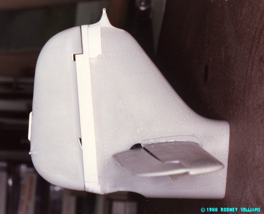
I used .016" thick flat aluminum stock for the "eye" hook for the antenna wire.
I used the old stand by cola/beer can .005" thick aluminum for the trim tab on the rudder. I removed plastic on both sides of the trailing edge of the rudder before I glued the two halves together. After the rudder was finished, I just slipped in the trim tab, and added super glue. The excess glue was sanded off, and presto, we have a trim tab that looks real, which can be bent slightly prior to painting.
There's not much to write about concerning the horizontal stabilizer elevator combination.
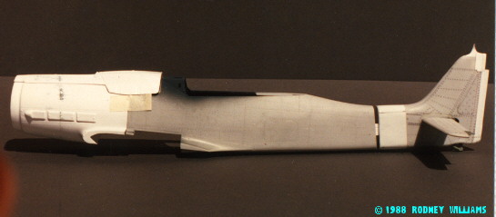
Auggie Hupp supplied a two part "vac-u-formed" fuselage extension for the D9 version. It was rather thin and really didn't mate up too good to the front nor rear section of the fuselage. I built the extension using .060" thick flat styrene. I added a couple of horizontal bars, which let me slip the aft section to the front section of the fuselage. It was tacked to the front with micro dots of super glue. After I finished trimming down the styrene, and sanding it, I just tapped gently on the area, and "pop" goes the super glue, and off it came. This gave me an ideal working solution. I can work on the front fuselage conversion section, without the tail plane attach. When building a model, just put your personal computer to work; (the one that is located behind your eyeballs, just click on "think", then click "enter").
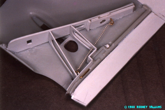
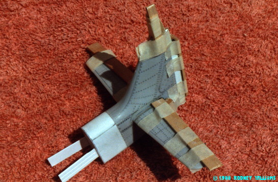
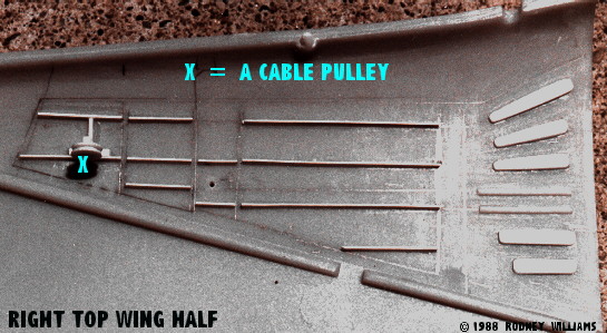
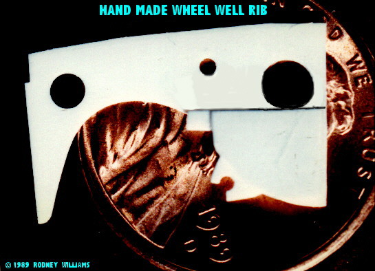
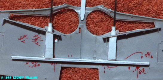
These two photos show how I built in the wheel wells, using a variety of styrene stock. I started using Future Floor Wax to glue on my ribs, etc.; (Look @ the top wing section photo). After it's dry, you can tack it with micro dots of super glue. This eliminates the glue build up along the ribs, and the cumbersome job of scraping and sanding off the glue.
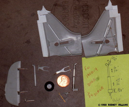
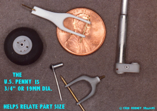
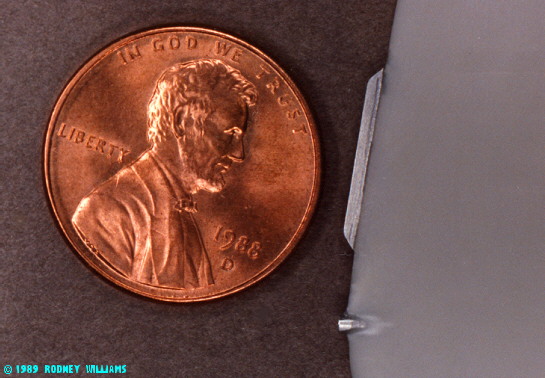
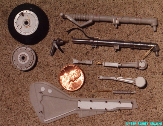
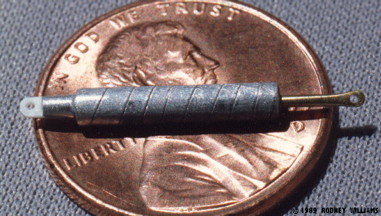
I photographed one on the ribs on the penny, which gives you a relationship for size of parts. Why not build this in 1/72 scale?
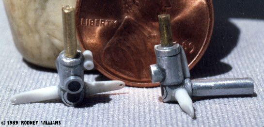
The cannon barrel was made from telescoping stainless steel tubing, and its' housing was hand crafted from round styrene tubing.
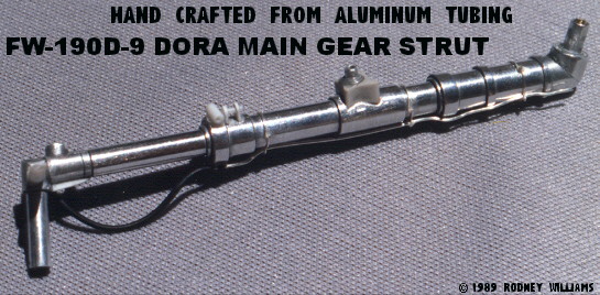
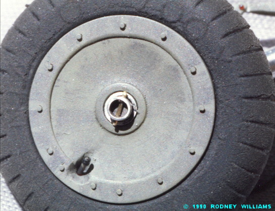
The next set of photos show the main gears, tires, rims, etc. The main strut was crafted by taking measurement from the kit strut, and the 3 view drawing. I used different sizes of aluminum tubing, which were glued together with Future Floor Wax. The wax allows you to adjust each item before it sets in and gets too hard for you to move the parts. If you make a mistake after the wax is hard, just soak the parts in Denatured Alcohol, as they will come apart. You can add micro dots of super glue, once you know you got it right!. Like other parts, the torque links were built, using the "pin-hinge" system of mine.
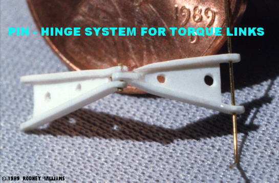
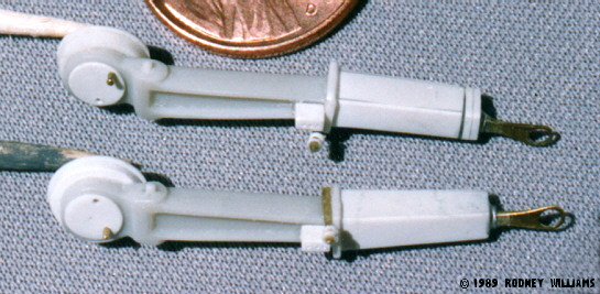
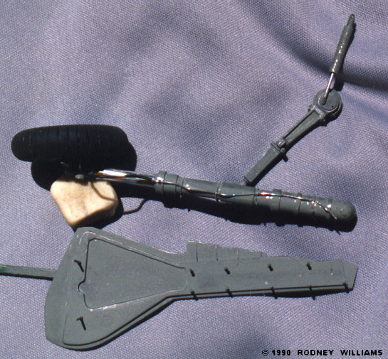
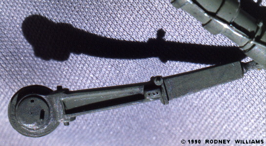
These photos show some parts put together with the little brass pins. On final assembly, these unpainted brass and red rods were cut to length, and inserted into the parts, then painted.
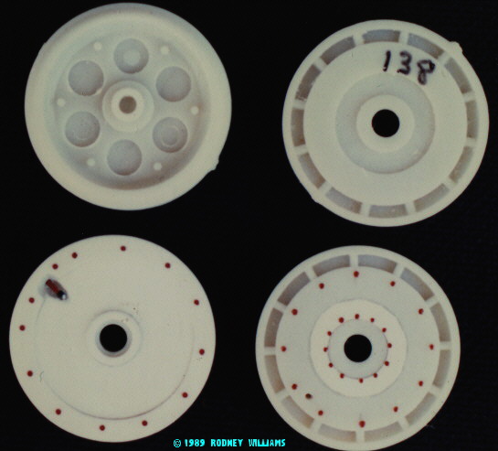
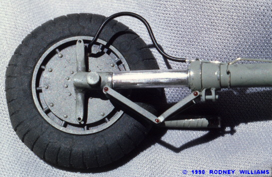
In the close up photo of the tire and rim you will see the valve stem and valve stem cap! It's on the real aircraft, so it has to be on your model. The same goes for any scale. The jokers at my club always ask? Hey Rodney, what happens if you get a flat tire? My reply is always: I use my hand made tire pump and put air back into the tire, after I patch the hand made inner tube!!!
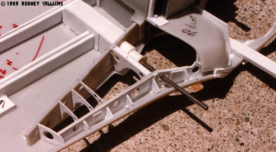
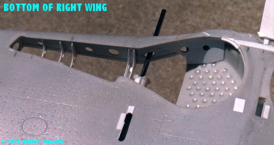
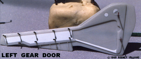
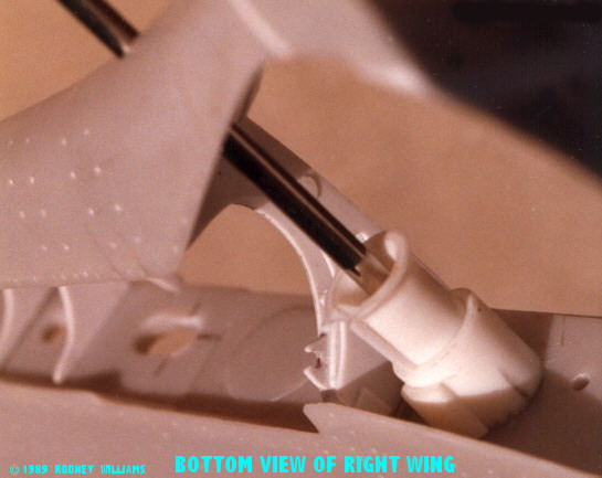
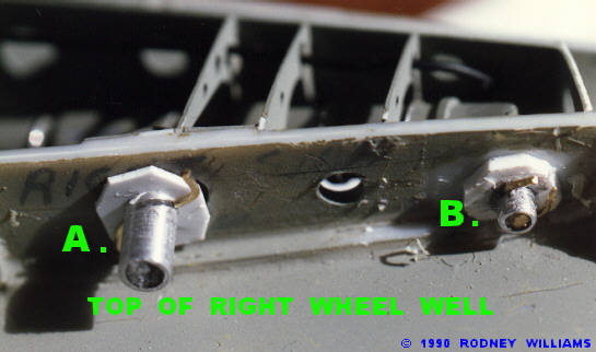
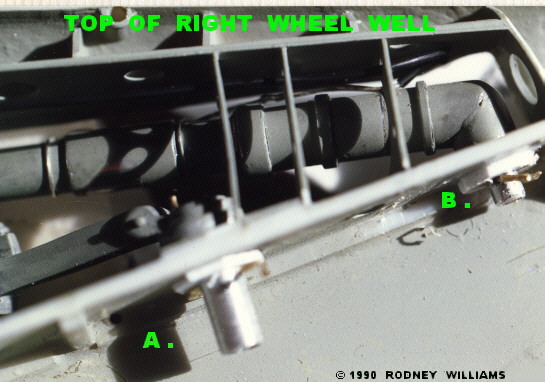
The last three photos in this segment show the main gear attached up inside the wheel well. The item marked with the letter "A" is the pin hinge system for the gear retraction arm, or what ever it's called. Pin "B" is for the main strut. This method let me install these items before I attached the top wing section. When it came time for final assembly, I could pull down the main strut and arm out of the wheel wells and attach the hydraulic actuator unit to its location, and adjust them for proper alignment! This is a must, and is nothing more than "BASIC'S!"
In my next segment you will see the addition of the front conversion section, the hand crafted exhaust stacks, radiator, and the revised cast resin prop supplied by Auggie.
Until next time, they say "happy modeling!"
To go to part 3
© Rodney Williams
This article was published on Wednesday, July 20 2011; Last modified on Saturday, May 14 2016