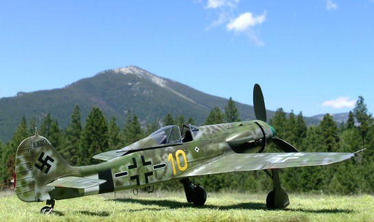
Hasegawa 1/32 Fw 190D-13 “Yellow 10”
By Ian Robertson
Background
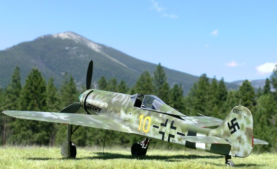
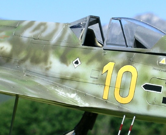
“Yellow 10” is a rare Focke-Wulf Fw 190D-13 that ended its wartime career in Flensburg, Germany, where it was surrendered to the RAF. Prior to its surrender the aircraft was the personal mount of Major Franz Götz, Geschwader Kommodore of JG26. “Yellow 10” has a remarkable history that extends from late war Germany to its current home at the Museum of Flight in Seattle. This aircraft’s journey, at least through its discovery in Germany, recovery in Atlanta, and restoration and display at the Champlin Fighter Museum in Arizona, before relocating to Seattle, is thoroughly documented in the book “Yellow 10: The story of the ultra-rare Fw 190D-13” by Jerry Crandall (2000, Eagle Editions). Excellent wartime and restoration photographs are included in the book, along with superb color artwork by Tom Tullis. The book was an invaluable resource for me while building this model.

The Fw 190D-13
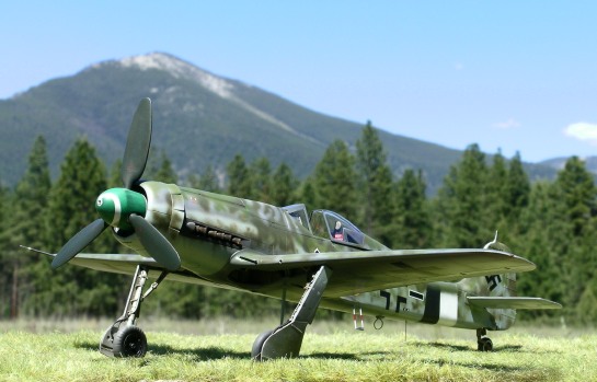
The D-13 variant of the Fw 190D series differed externally from the D-9 variant in the following respects: redesigned upper cowling in front of the windscreen, wider engine cowl with larger supercharger intake, VS 9 paddle-bladed wooden prop, and a single ejection port for the engine-mounted MG 151 20 mm cannon that fired through the spinner. A number of other minor refinements dealing with the position of access panels were also present.
Jerry Rutman (J. Rutman Products) produces a high-quality and well thought out conversion set for Hasegawa’s new-tool 1/32 Fw 190D-9. While the conversion is not for beginners, those with moderate modeling experience and experience working with resin should find it straight forward.
In addition to the Hasegawa D-9 kit and Rutman D-13 conversion, I used the following parts on my model:
- MDC main wheels (treadless) and tail wheel - Superb detail. Brake lines are included for the main undercarriage.
- MDC seat belts and buckles
- Cutting Edge resin seat
- Eagle Parts Fw 190D radiator cowling (#43-32)
- EagleCals decals #32-59- Printed by Microscale, EagleCals are thoroughly researched and among the best aftermarket decals available. The airbrushed profiles by Tom Tullis are superb.
Construction
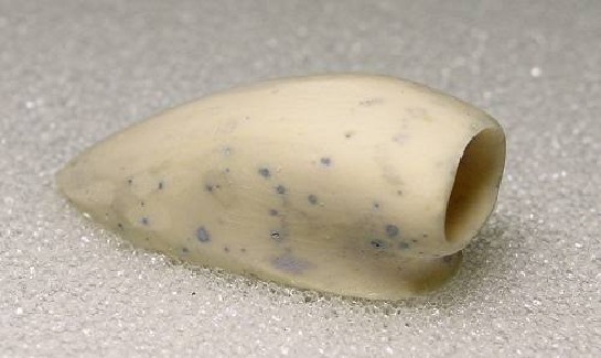
The resin fuselage halves were well cast and needed only a minor amount of cleanup around the wing roots and cockpit. However, the supercharger intake, upper cowl, and prop blades suffered from numerous pock-marks that required filling and sanding. On the supercharger intake I used a dremel tool to hollow it out.
Because the Rutman conversion is designed to replace specific parts of the Hasegawa kit, construction proceeded more-or-less as shown in the Hasegawa instructions. When gluing the fuselage halves together great care is needed to ensure proper fit and alignment of the wings and tail to the forward fuselage. Therefore, I jumped ahead in the Hasegawa instructions and completed the wing assembly so that it could be used in dry fitting to the fuselage.
The wing flaps on my model were closed for pragmatic reasons - according to Jerry Crandall, “Yellow 10’s” flaps were made from wood and therefore the internal ribbing on the kit’s flaps is incorrect for this particular aircraft. Solution – flaps up.
Turning to the cockpit, I replaced the kit seat with one from Cutting Edge, and I added etched brass belts and buckles from MDC. Guide rails on each side of the seat back were made from Evergreen styrene. The cockpit was painted RLM 66 using Polly Scale acrylic.
Proper insertion of the cockpit and engine plug required careful dry fitting and some minor adjustments. Remember that the resin fuselage halves are thicker than the kit’s styrene parts, so some thinning is required for the cockpit and engine plug to fit properly. I opted to thin the width of the cockpit floor rather than the fuselage side walls. The same was true for the engine plug.
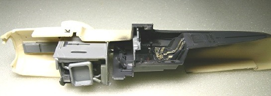
Before gluing the fuselage halves together, don’t forget to add the wells for the exhausts. Note once again that because the resin fuselage is thicker that the kit parts, the exhaust wells sit a little deeper than they should. Reducing the depth of each well before attaching it to the interior of the fuselage is the best option. I learned this lesson the hard way when my MDC exhausts nearly disappeared into the uncorrected wells. However, the kit exhausts fit satisfactorily in the uncorrected wells, so ultimately I used them.
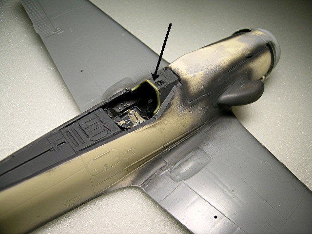
As in the Hasegawa kit, placement of the gun sight is incorrect in the Rutman conversion because it interrupts the padding that extends across the front of the coaming above the instrument panel. Therefore, once the fuselage halves were together, I repositioned the gun sight further forward and added a strip of styrene rod to fill the gap in the padding.
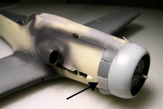
I chose to display the cowl flaps open. One point of interest – one of the cowl flaps on the starboard side of the Hasegawa part is molded shut, consistent with numerous photos of D-9s, including a photo on pg 77 of Jerry Crandall’s book. However, the photos of “Yellow 10” show this flap open. While I’m not certain of the significance of this discrepancy, I chose to modify the kit part so my model would be consistent with the photos of “Yellow 10”.
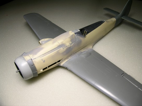
Attaching the tail and wings was easy given the careful dry fitting that preceded. The small insert between the wheel wells fit perfectly as well. At this point main construction was complete and the model was ready for painting.
Painting
Painting of the outer surfaces began by spraying the model with Mr. Surfacer 1000. The wheel wells (RLM 02), cockpit, and engine face were masked prior to the application of the primer. Once the primer was dry I polished the model with a Micromesh sanding cloth. I then painted and masked the JG26 fuselage bands on the rear fuselage. Note that the white and black bands were unequal in width and not parallel.
I preshaded the model with black paint and then polished it again. Alclad II aluminum metalizer was sprayed on the wing roots. The metalizer in this area would later be exposed to simulate scuffed paint.
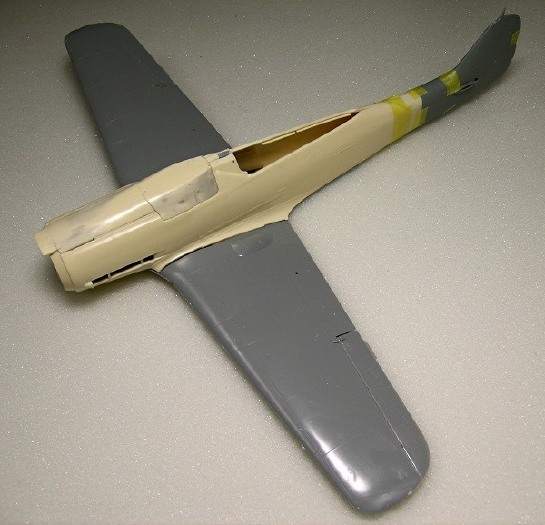
The underside of “Yellow 10’s” wings were natural metal with RLM 75 on the leading edge and RLM 76 on the ailerons. I used Alclad II for the metal surfaces and weathered it slightly with washes of thinned Tamiya black acrylic. The natural metal surfaces were then masked for application for RLM 75 and 76 using Polly Scale acrylics.
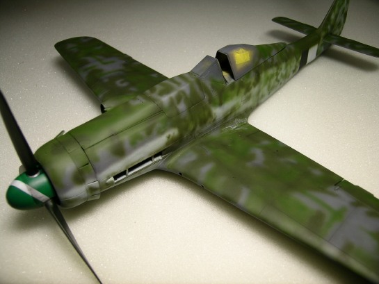
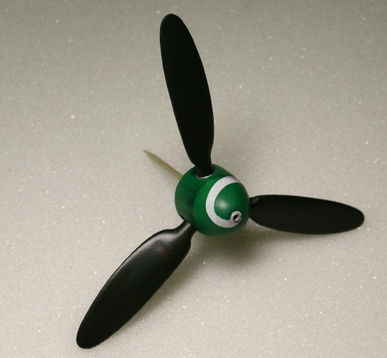
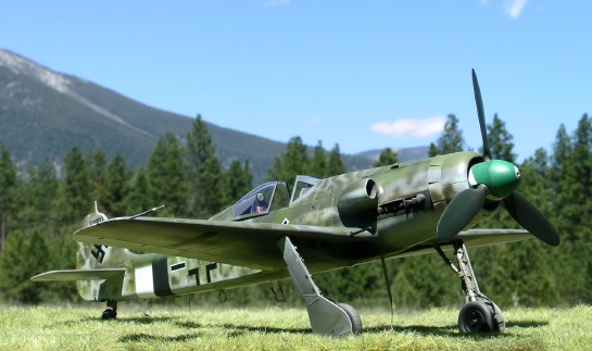
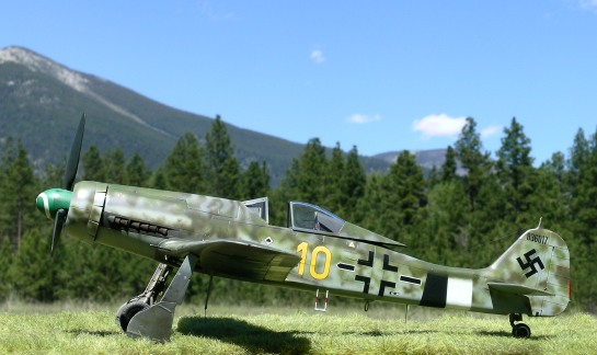
The fuselage was painted RLM 76. Afterward, the upper fuselage and wings were painted RLM 75, as described in the painting guide for “Yellow 10” on the back cover of Jerry Crandall’s book. For the complex pattern of greens I followed Tom Tullis’ artwork as closely as possible. The colors applied to the upper surfaces were my own mixtures to represent RLM 82 and 83. I am not satisfied with most interpretations of RLM 82 (hellgrun) by paint manufacturers since the color is typically formulated shockingly bright. However, White Ensign Models provides formulations of RLM 82 and 83 that were exactly what I was looking for. Therefore, I used the lids of my WEM paints as paint chips for mixing my own RLM 82 and 83 using Polly Scale acrylics. (Why, you may ask, did I not simply use the WEM paints? Honestly, I’ve developed a comfort zone with Polly Scale acrylic and didn’t want to experiment with a lacquer paint I’ve never used before.) My mixture for RLM 83 (dunkelgrun) was 1 part Polly Scale “Pullman Green” (similar to RAF green) and 1 part Polly Scale RLM 81 (brown-violet). This gave a distinctly brownish green appearance to the paint. My mixture for RLM 82 (hellgrun) was 1 part Polly Scale RLM 82 and 1 part Polly Scale RLM 83. The spinner was painted RLM 25 with RLM 70 prop blades. Although the Eaglecals’ decal sheet provided a spiral decal for the spinner, I believe it was designed for the shape of the Hasegawa spinner, not the resin replacement. After several unsuccessful attempts to find a suitable spare decal, I opted to paint the spinner white, mask the spiral using Tamiya tape, and then reapply the RLM 25. Note the stains on the rear half of the spinner – these were caused by fluids leaking through the hole of the propeller hub for the cannon blast tube. To simulate this effect I masked the forward part of the spinner and then sprayed highly thinned back paint across the rear half of the spinner in the direction of air flow. To simulate paint chips at the wing roots, I used fine grain sandpaper to create surface abrasions and expose small amounts of the Alclad II aluminum beneath. The Eaglecals decals performed flawlessly over a gloss coat of Future floor wax. Microset and microsol helped the decals conform to the model’s surfaces. Once the decals were dry I applied a 50/50 mixture of Polly Scale clear satin and clear flat acrylic. To each landing strut I added brake lines made from wire and thin, flexible rubber. The oleos were covered with bare metal foil, and the holes in the oleo scissors were drilled out. I also added some additional wiring to the radius rod hinges. An interesting detail of “Yellow 10” is that the starboard tire had a tread whereas the port tire was smooth. The MDC replacement tires, as well as the kit tires, were suitable only for the port tire. I simulated a tread on the starboard tire by scoring the MDC tire with a knife and then widening the tread with a scribing tool. Note that Eagle Editions makes a perfectly suitable treaded replacement tire. A wooden cutting board was used as the base for the model. Celluclay was used to make the basic ground cover. The celluclay powder was mixed into a paste with water and white glue, tinted with brown acrylic paint, and then spread thinly over the cutting board. Note that the cutting board had previously been treated with several coats of clear lacquer to prevent warping while the celluclay dried. While the celluclay was still wet I added pieces of Heki grass mat (item # 1574 - Wild Grass Savanna), fine sand, and small bits of moss. Heki Grass is now available in the United States from Scenic Express. Images of the completed model were taken with a Nikon Coolpix 5400 digital camera in Montana. The Bitterroot Mountains provide the aesthetic backdrop. © Ian Robertson 2005 This article was published on Wednesday, July 20 2011; Last modified on Friday, June 02 2017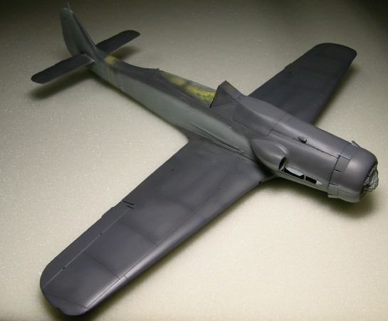
Decals
Adding the Undercarriage
Groundwork
Photographs