
Scratchbuilding the MS-406
By Howard Weaver
The first thing needed to start a project like this is a set of good 3 view drawings. There are several sources for plans, and after obtaining them, they must be enlarged to the correct scale. I used a local self serve copy service for this and made several copies to work with. The copy machine I used will enlarge or shrink drawings by percentages.
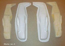
I next transferred these patterns to the wood by simply gluing them directly to the wood surface with school glue. I use basswood for my masters. After the glue had dried, I cut the pieces out with a scroll saw. One thing to remember here is that each piece of the model will need to be made in two halves so they may be vacu-formed in individual halves later. See photo no.1. and 2. I used a dowelling method with the two fuselage halves so that they could be put together for shaping, and could easily be taken apart later for vac-forming. The wings were done in a similar manner, except that they were tack glued together with CA glue for shaping. They were easily separated when finished with a kitchen knife by inserting the blade into the joint and forcing the two halves apart
At this point, I obtained a copy of Le Morane-Saulnier MS 406. published in France by Avions, 336 pages. The text is all in French, but the excellent photos have captions in English and in French. This book has hundreds of photos of the MS 406 with detailed photos of landing gear and cockpit shots. It was an indespensable tool for building the MS 406.
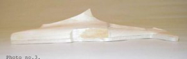
Now each piece needs to be prepared for vacu-forming by gluing a spacer piece to the bottoms of each piece that is to be formed. I used balsa wood for this. This needs to be done to insure that you will get good, full vac pieces. During the vac process there is a radius formed at the junction where the mold meets the vacu-form plate. By spacing the mold up 1/8. to 1/4. you can trim off this part and obtain two good full halves. See photo no.3 and 4. An article on a vac-forming machine can be found elswhere on this site.

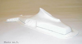
After the pieces were formed, I used a sharpened nail glued to a popsicle stick to act as a scriber. I spaced it up untill the point was exactly the height of the thickness of the balsa spacer and scribed all around each piece. Then this groove was filled with graphite from a pencil. This gaves a good reference line to cut the vac piece to when trimming them out. See photo no. 5.
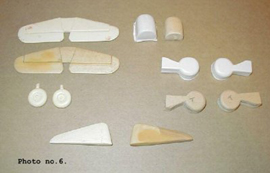
Other pieces that were too small or not suitable for vac forming were cast in resin after making master pieces and the making RTV molds of them. This included wheels, rudder, and tail assembly, See photo no. 6.
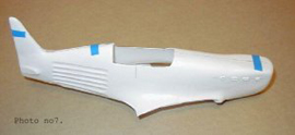
After each vacu-formed piece was trimmed out, they were trial fitted together and matched up. See photo no. 7.
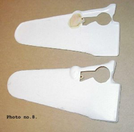
The landing gear has to have a good solid anchor point in each wing,. Photo no. 8 shows the upper of one and the lower views of the other, with basswood blocks epoxy-glued in place in each wing to provide these anchor points.
The rest of the build goes the same from this point as any vacuform model.
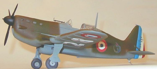
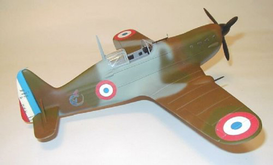
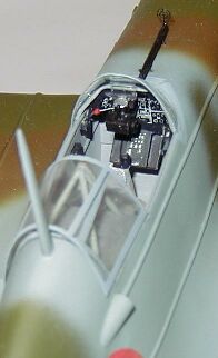
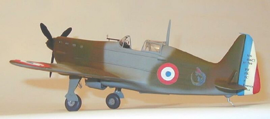
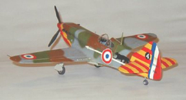
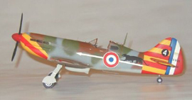
The cockpit, landing gear, and other details have to be scratchbuilt and added to the model. I made all of the markings with my computer and Alps printer...The model depicts an Ms 406 flown in 1939 and 1940 by Capt. George Lacome during the battle for France.
I hope you enjoyed this article. Maybe someday I.ll do a variation of the MS 406 and do a Morko Morane.
Happy modeling!
The other French fighter (also scratchbuilt) by Howard Weaver is the D 520.
© Howard Weaver
This article was published on Wednesday, July 20 2011; Last modified on Saturday, May 14 2016