
Trumpeter 1/32 TBM-3 Avenger Part 1
By Gene Nollmann
Background
In answer to a US Navy request for proposal of a 300-mph, 3000-mile range torpedo bomber to replace the TBD Devastator, Grumman received an order 8 Apr 1940 for 2 prototype XTBF-1s, which were to eventually evolve into the production TBF-1 Avenger. By the close of World War II, nearly 10,000 were to be produced, first by Grumman (2,291-TBFs) and finally by the Eastern Aircraft division of General Motors (7,546 -TBMs). Simultaneously Grumman had produced the TBF-1C and Eastern the TBM-1C. With the installation of the more powerful Wright R-2600-20, the TBM-3 was introduced, the first prototypes flying in October 1943, and produced exclusively by Eastern Aircraft to free-up Grumman's production lines for the F6Fs.
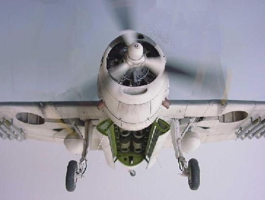
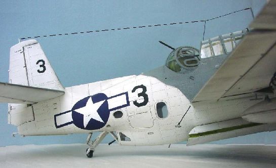
With so many of the type having been produced, the Avenger saw action in every theater of the war. The Avenger in grey and white camouflage particularly caught my eye; the size and coloring reminded me of an Orca, a.k.a. Killer Whale. This was the Atlantic Anti-Submarine Scheme II and was worn by Avengers used in the longest battle of World War II, The Battle of the Atlantic. Assigned to ships originally destined to be merchant vessels but then converted to escort carriers, known as CVEs (Carrier Vessel Escort), the Avenger joined a complex team of technology and personnel to hunt and kill Axis U-boats in the Atlantic.
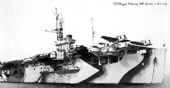
William T Y'Blood's well written account, Hunter-Killer: US Escort Carriers in the Battle of the Atlantic, describes in detail the complex coordination involved. Using HF/DF radio intercepts, Enigma encryption decoding, the CVEs with their destroyer and destroyer escorts directed F4F Wildcats in hunt and fire suppression and Avengers in hunting with a trained eye, radar, sonobuoy sonar, and firing rockets, dropping iron bombs, depth bombs and torpedoes to disrupt U-Boats activity all over the Atlantic. During February 1943, just as the USS Bogue went to sea and the CVE hunter tactics were being formed, 600,000 tons of Allied shipping were lost to the U-Boats in that month alone. By April 1945 of the 1162 U-Boats produced, 785 were lost to enemy action. This is a result of all Allied activity to stop the U-Boat assault, but the Avenger made a significant contribution to the coordinated effort.
Most Sub-hunting Avengers were probably TBF/TBM-1, -1Cs, but by 1944 TBM-3s were coming off Eastern's production line at nearly 10 per day and were making their way to the Atlantic theatre. This model represents one TBM-3 photographed on the foredeck of the USS Bogue February 1945. The USS Bogue being one of the definitive CVEs of type and the highest scoring US Navy Sub-Hunter in the Atlantic.
The Kit
My original intention in opening the Trumpeter TBM-3 kit was to compare it to the Scratchbuilder's TBF/TBM kit that is now out of production, having no actual intention of building the Trump kit right away. Little did I know - there should have been a warning the kit was vacuum-packed -- like a good mystery novel, once the box was opened, it could not be put away! It sucked me right in with one challenging and rewarding sub-assembly after another.
The kit totals 568 parts, 484 injected parts on 17 sprues, 1 PE brass fret of 25 pcs., 1 PE stainless fret of 39 pcs., 15 steel pins, 1 short length of miniature rope, 2 main and 1 tail tire of hard vinyl, 1 film piece with instruments faces, and 1 decal sheet with markings to do one of two aircraft. The finished plane has a wingspan of 20.31-inches (517-mm) (full size 650-inches) and a length of 15.15-inches (384.8-mm) (full size 484.72-inches).
At the risk of boring many gifted modelers (I apologize) and with the understanding that I am not an 'expert' on the Avenger but just a modeler groping my way through this new kit with a desire to share what I've learned about its peculiarities, the following comments are offered to highlight some aspects of this latest kit offering from Trumpeter.
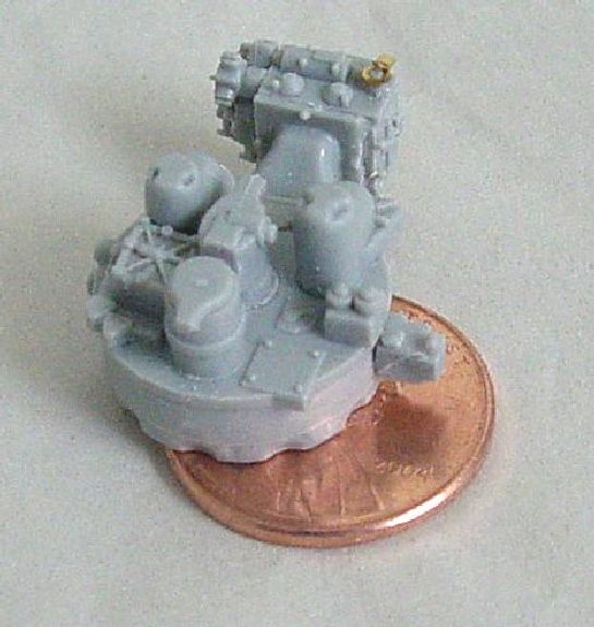
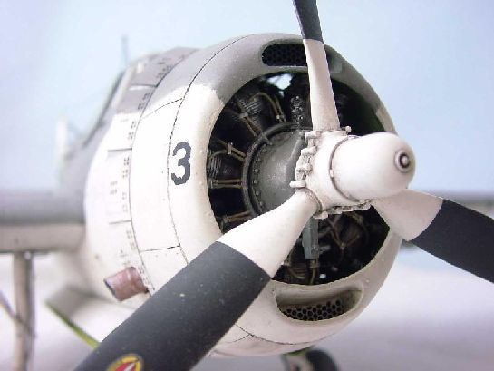
Steps 1-4 - the engine
The introductory assembly is the engine induction and controls case requiring 18 pieces that when all assembled is scarcely larger than a penny. It will be mounted to the back of the firewall and unless you open an inspection hatch, it will never be seen in the final assembled model. But if you want to open a hatch, hold back glueing the firewall piece F17 and the ring structure piece D16; you might find it more convenient to detail this area assembled in a different manner.
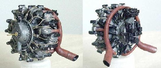
The engine assembly (with a few pieces borrowed from Steps 23 and 58) will give you a 78-piece engine. Just add 28 plug wires and a couple of misc. hoses and you get a pretty nice R-2600-20. Seems the only visible difference between the TBF-1C's -8 and the TBM-3's -20 is a little chin extension. Working space is a very tight but the parts fit is great. Even a wiring ring-harness is provided that allows a proper spacing of the plug wires, if you choose to add plug wires. I cut the nubs on the ring and used the mark for drilling holes for the plug wires. Some detail can be added back in for the plug cable fasteners.
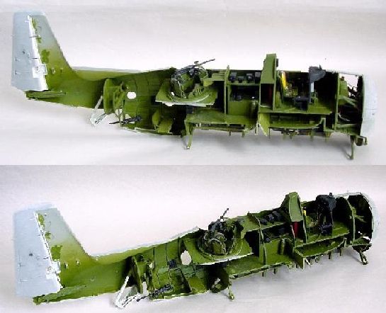
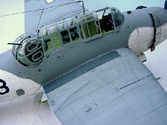
Steps 5-13 - the cockpit and electronics cabin
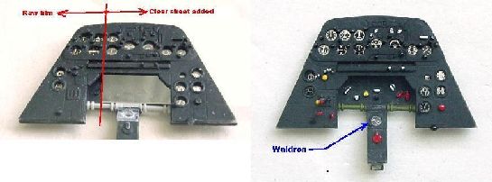
One of the visual differences between the -1C and the -3 is apparent in the instrument panel; the -3 has a flat top and a slightly different cluster of instruments. The kit comes with an instrument 'film' to be placed behind the dial face openings. The film is glossy but doesn't quite give that 'under glass' effect, so I tried putting a .005" acetate between the film and the dial opening. That seems to reflect about the right amount of light. I also sanded the backside of the injected instrument face to minimize the depth of the instrument bezels.
10 pieces make-up the stock kit instrument panel assembly. The center console is missing an instrument dial graphic although a separate glue on dial face opening is provided. Ref indicates the instrument is a 'remote indicating compass', which Waldron does not make, so I substituted with one that comes close in appearance.
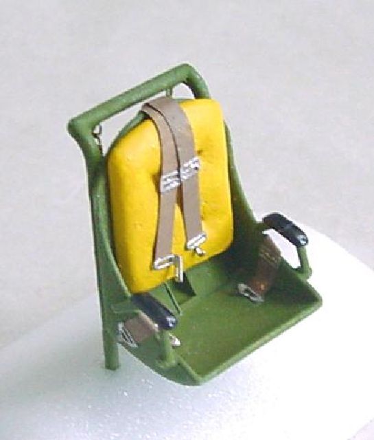
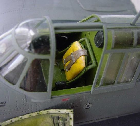
The pilot's seat is just 8 pieces, so I felt obligated to add a few more, first, a seatback cushion out of Milliput, second, a couple of seat suspension springs and hooks. It appears that earlier Avengers used bungee chords and later a change was made to springs. I used the kit supplied PE belt/buckle, but an aftermarket PE belt/buckle would be very worthwhile here.
The cockpit is pretty straightforward assemble and paint. I added the 'map tray' in aluminum but was way too bright, so it was toned down. The cockpit side panels are several steps away. In the electronics cabin I cut the top row of boxes off, set them on small legs and added knobs, switches, and wiring. (Now I know how Flight 19 got lost if they wired their radios like mine!). Once installed the second tier below is nearly impossible to see - so no one will ever know if I hooked them up correctly or not!
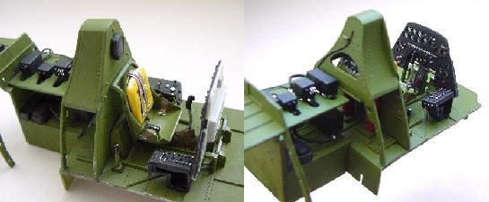
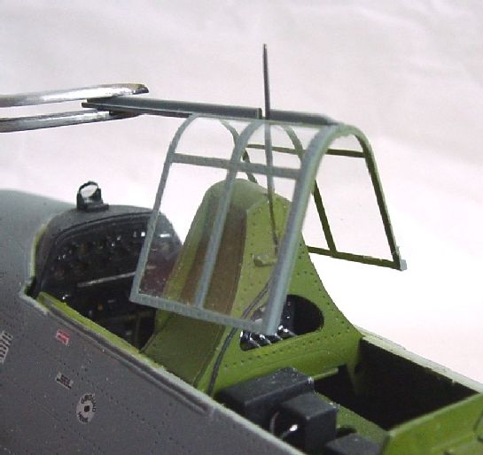
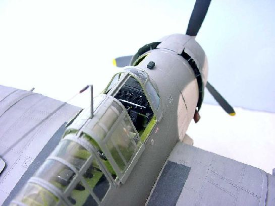
The radio antenna mast was replaced by one fashioned out of brass (scrap from the PE fret and built up with CA and profiled). The mast was made long enough to reach down to the molded in 'wiring'. The bulkhead was routed to receive part of the antenna (for strength). A hole was drilled in the canopy piece and squared off to allow the antenna to pass through.
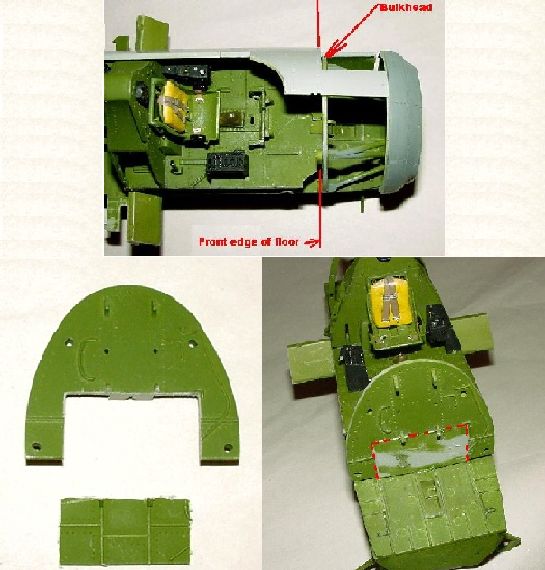
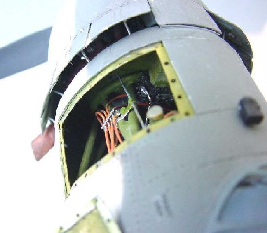
One decision I kept putting off is whether or not to open up the inspection hatch to expose the back of the engine, the support frame and the oil reservoir. Well, step 33, 'the closing of the fuselage', finally forced a decision and I decided to give it a go.
Carefully scoring away the cover and then test fitting the interior bulkhead reveals why Trump may not have provided the kit this way in the first place; the bulkhead winds up too far forward and is exposed by the hatch removal. I hate cutting into 'virgin' painted plastic but cutting the bulkhead to saddle the end of the cockpit floor pushed the bulkhead back far enough to be in a convincing position with the hatch open. Now the bay can be plumbed and displayed open. Note how the bulkhead is 'saddle cut' and flushed to end of cockpit floor:
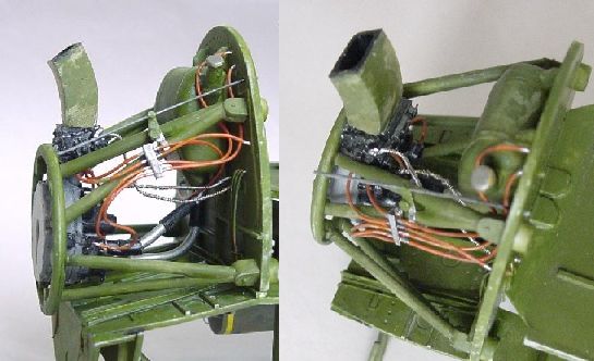
To further ease this process I removed the 'back of the engine' (the very first piece assembled in step 1), which is normally attached to the 'cowl firewall'. I sanded off all the alignment lugs on both the 'firewall' piece and the 'back of the engine' piece and attached it to the 'engine support framing' (with a goop of glue at the point where the carb passes over the circular frame). This was done to allow the clearest access to run plumbing and wires. Also when the cowl firewall is finally attached to the fuselage, I won't have to worry about precise fit (although it is possible, why torture myself anymore than necessary?). In addition to the plumbing and wire, it was necessary to add the duct that picks up and the firewall and runs down to the top of the carb. I don't know how many CFMs this will run, but the measuring units could easily be whole legs and arms!
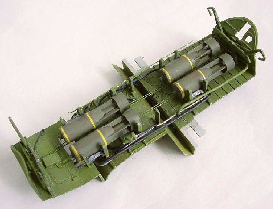
Steps 14-22 - the bomb bay and its load
The Trump kit provides a nicely detailed bomb bay that can look good as a stand-alone. The Trump kit also provides several bomb bay installation options including a 270-gal. fuel tank, a Mk.XIII torpedo, four 100-lb. bombs, and four 500-lb. bombs.
Earlier in the Battle of the Atlantic, Avengers were noted by Y'Blood to be dropping Mk.47 depth bombs and 500 pounders. Occasionally the Mk.24 'FIDO' torpedo was used, which was a sound homing torpedo that was only 7 feet long. Apparently it and a couple of bombs could fit in the bomb bay. Later in the war Y'Blood more frequently mentions the Mk.54 depth bombs and the FIDO as well as Sonobuoys. Coupled with the 5" HVARs and the wing cannons, the Avenger was a pretty lethal weapons platform.
I decided to load my Avenger with Mk.54s and modified the 500 pounders into Mk 54 depth bombs. A little research gives a diameter of 13.5 inches which is what the kit supplied 500 pounders measure, so I started with cutting that and adding bits and pieces to resemble the drawing in Squadron's Avenger In Action (pg. 19).
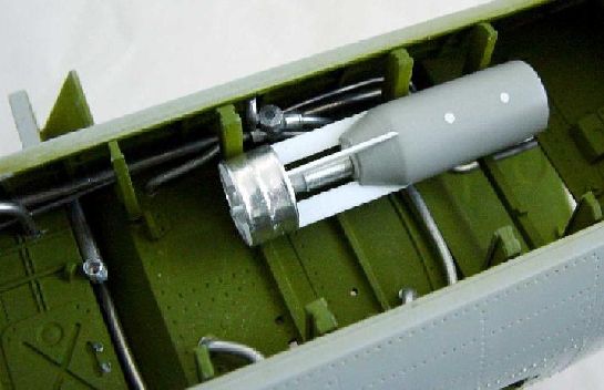
Making one was fun, making 3 more a little tedious, but really not that bad. The bombs were painted with a Testors Acrylic Olive Drab and the yellow bands were cut from a decal sheet of Expert's Choice Chrome Yellow. These colors may not be the correct ones to use, but it seems to sit well in the bomb bay. According to Avenger In Detail & Scale, the mounting racks used by the hundred pounders was also used for the depth bombs. The Trump kit provides nicely detailed representations of the racks, but alas, is very deep in the bay.
Step 23 brings the cockpit, electronics cabin and bomb bay together to form the 'backbone' of the fuselage. One can test fit the fuselage halves here to make sure everything is coming together as expected. The phrase that Ed Kinney of IPMS USA coined for this kit is very appropriate - 'click' fit - one can almost hear the precision fitting of parts!
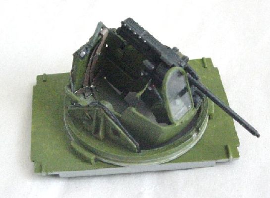
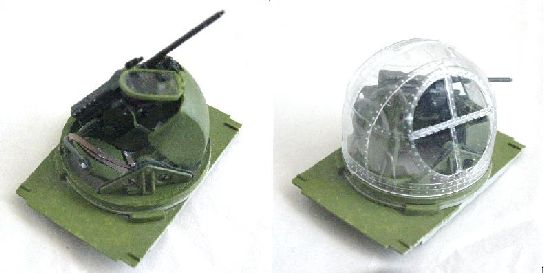
Step 24-27 - ball turret
The kit supplies 37 pieces for the ball turret and I put in a few more cable runs here and there, but when the glazing goes on it all becomes very difficult to appreciate!
In order to allow the gun/seat assembly to easily rotate under the glazing, several surfaces needed to be shaved and the dome raised with a piece of 0.060" Evergreen styrene placed on the mounting ring. The fit in the fuselage is snug, but the turret will now turn and rotate so I can pose it in any reasonable position.
The oxygen regulator was moved to match one of my photo refs and further detailed with a hose, etc. The new location also helps the seat clearance in its rock inside the turret.
Steps 28-33 - closing the fuselage - finally!
Step 28 assembles the bulkhead holding the tail wheel structure and the sub-frame holding the flare tubes and the corrugated top surface is where the round aircraft float lights (not in kit) are stored. The fuselage has a deep recess where the flare tubes would exit. The tail gun is mounted now, but becomes quite a nuisance when painting the fuselage. I mounted mine after painting, but wished I had devised a better way of securing it in the finished model.
Just so the tailwheel could be posed, I cut the unit at the castor swivel point and drilled for a small brass rod so that the tail wheel could be swiveled to a different angle (not out of sorts on a carrier deck were aircraft are shuttled around quite a bit).
There are a few bits and pieces to add to the tail compartment; one could go real nuts here (especially if you have no other models you would like to build over the next 2 or 3 years). The access door can be mounted closed or open and offers a fair view to the opposite sidewall and the numerous portholes allow some light. I just did the basics because I was now eager to get on with the next steps.
When it is finally time to bring the two fuselage halves together, there are 12 or so distinct alignments points waiting to spoil an otherwise fun build. Aside from the little wrinkle I introduced to open the hatch to the engine accessory service bay, the fuselage halves come together with a superb fit (again a "click-fit") much to the credit of Trumpeter's engineers and kit ingenuity. All through the build I was constantly testing the fit as each sub-assembly was finished, just to be sure I wasn't guiding the construction down a disappointing path, but all along I was impressed over and again how this complex kit was coming together.
One building this kit might take notice that the ball-turret framing is a very tight fit into the fuselage and might need to be painted before the fuselage halves come together.
Also, the fit of the instrument panel coaming is not that great and should be resolved before the panel is glued into the cockpit and the fuselage halves are joined (and also observing the assemblies prefit as the fuselage comes together).
In the next two steps, all the small fuselage side windows are added. Being spoiled by the great fit of parts I didn't anticipate any problems here, but problems might be observed in the depth allowed for the window's mounting. Several were too deep; having this to do again, I would fuss with the window mountings till they were more flush with the fuselage before I joined the fuselage halves.
Step 34-35 - adding to the fuselage and the engine cowl
One might wonder why some of the PE detail on the inside of the bomb bay doors was not etched all the way through - when the doors are folded to the fully open position the question becomes why are those pieces PE at all, the detail is well hidden. Anyway, they assembled nicely; I held off mounting them till the very last as they appeared to be a great way to break off parts accidentally.
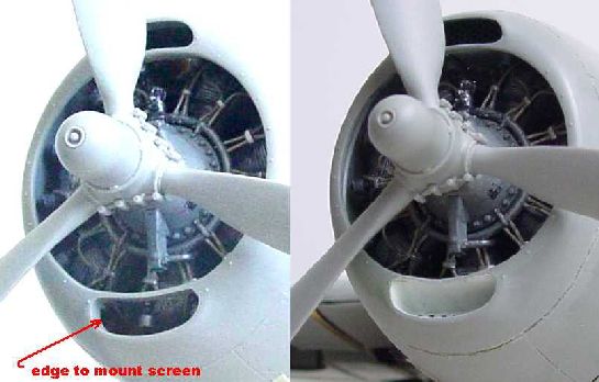
The kit provides two photo-etched screens to back up the front cowl scoops. Their mounting is quite near the front and would block views of the engine (which is good, one should not see the engine through the scoop openings) but would not give the appropriate presentation of ductwork that photo-refs show. So I built the ductwork and added a few interior pieces that might be visible from the front of the cowl opening.
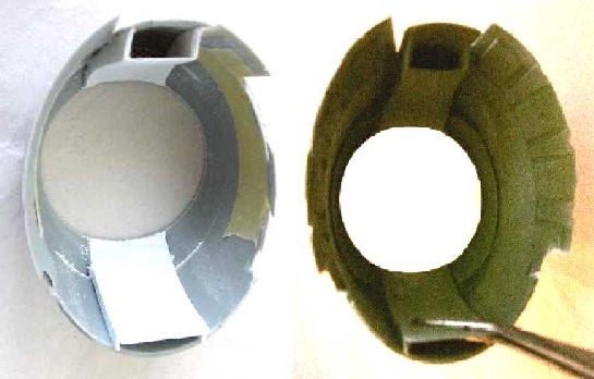
The kit offers two cowl flap position options - open or closed. The closed pieces are nicely detailed (the raised rivets are a bit too high however), but the open pieces lack appropriate detail and in fact show the cowl flaps incorrectly butted edge to edge when they are open (also lacks the 'scalloped-edge' effect of the open flaps). So I cut the 'closed' pieces, carved in the underside shapes, added flap connector plates and finally at a later time, pushrods.
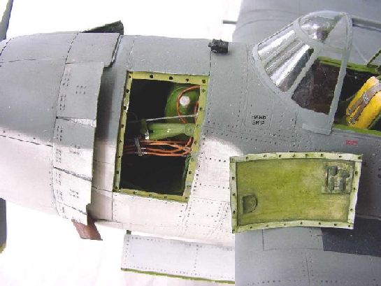
One curiosity is how the top of the cowl meets the fuselage. I ran across a photo of the top of the cowl, which shows a distinct open space very much like the kit (and not a continuous smooth 'clean' surface from cowl to fuselage). However, just below is the intake duct penetrating the firewall, so a little detail can be added there, which also offers a way to secure the top of the cowl to the fuselage. If you decide to run duct work, have caution that the clearance from duct to engine is a lot tighter than one might anticipate. ------to be continued------
© Gene Nollmann 2005
This article was published on Wednesday, July 20 2011; Last modified on Saturday, May 14 2016