
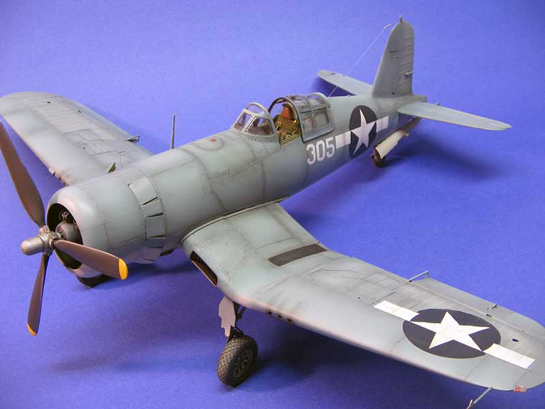
Trumpeter 1/32 F4U-1 Corsair - Backdated Birdcage
By Damian Murphy
There has always been a fascination with US Navy aircraft and model builders.
The appeal of a war torn, hard hitting pacific fighters and there perilous battles in the remote sun baked islands of the Pacific Ocean, have spawned countless scale replica and diorama recreations.
The F4U for me has always held a special attraction having modeled countless kits in many scales and until the release of the Tamiya 1/48th scale corsair birdcage, modelers had only the choice of the 1A or 1D or the -4 versions in 1/32nd scale.
Recently while browsing the multitude of after market resin kits I happened upon a gold mine for the 1/32nd scale F4U, a conversion kit from Mike West of Lone Star Models. A basic kit, that includes a cast resin aft deck and two styles of the framed canopy fashioned in vacuform.
Finally I had the opportunity to build an F4U-1 Birdcage in 32nd scale I decided to use the Trumpeter F4U- 1D as the basis for the design, the Trumpeter kit while being one of the newest kits on the market lacks detail throughout the kit but panel line detail is abundant. As with most Trumpeter kits the cockpit on the F4U kit is extremely inaccurate. While the entire late model Corsairs from the -4 model on had floor boards, the early models such as the -1 to -1D were floorless. I decided early in the planning not to use one of the after market resin cockpits. I wanted to do some serious scratch building in this project, with that in mind I used sheet evergreen to build all the components of the cockpit with the exception of the cockpit seat and control stick.
Cockpit
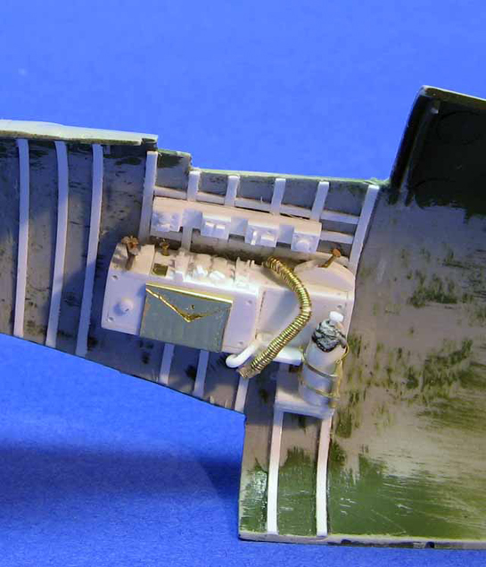
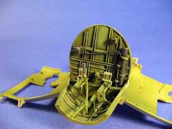
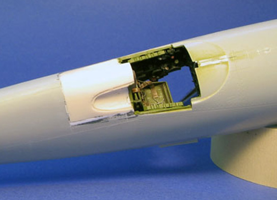
In this picture you can see that the mock up of the cockpit is built in a compartment style build, using the floor of the wing section to form the curvature of the lower floor. I used this sheet evergreen plastic with stiffeners constructed out of evergreen strips along the edge. The forward section bulkhead is a double wall construction to add support to the forward curvature, and then I lay in detail strips to simulate the framing of the aircraft. Normal Testors tube glue works fine with evergreen plastic and melds rather quickly. The foot kick plates are constructed out of ¼ inch tubing cut in half and sanded down to the proper proportion.
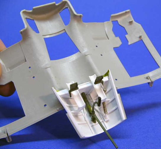
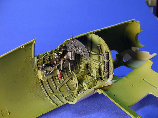
When I started the construction of the cockpit walls I again used evergreen plastic strips to create the frame work. I use .040X.060 and .010X.060 strip styrene. When building the side control panels I constructed a box then added various switches a dials, made from brass rod, and plastic rod. Brass sheeting was used to make such things as map pockets and oxygen hoses were made of thin brass rod wound and coiled to simulate the flexible hose. Be creative here accuracy is nice but sometimes you just have to use Sheppard Paigne’s idea of gizmology.
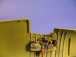
The other side of the cockpit was constructed much in the same way as the first side, but with the addition of the throttle quadrant this side was a bit harder to construct. After everything was allowed to dry I then started on the aft bulk head and seat construction.
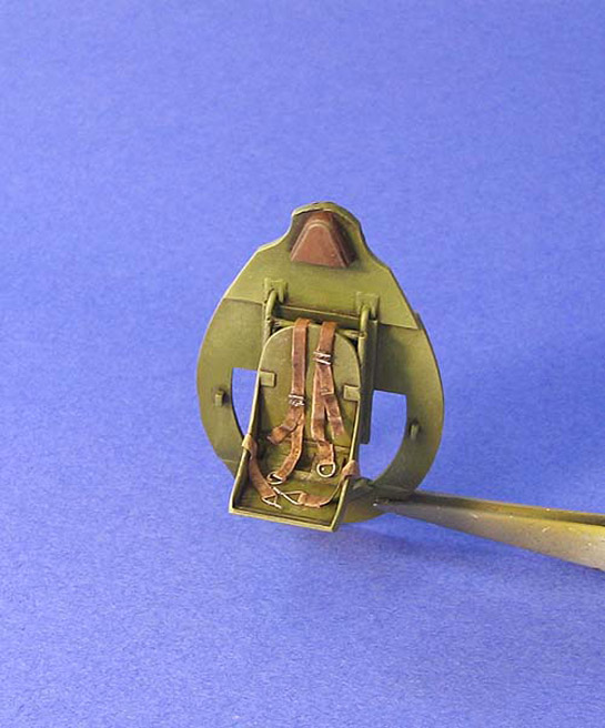
Seat Construction was basic I had decide to use the kit seat, and I modified the kit rear bulkhead. Construction of a complete new seat rail and the addition of plastic were used to build up the area of the lower bulkhead to compensate for the removal of the kit floorboard, inaccurate to the F4U-1. Seat harness was cut from thin sheet brass, and buckles were made from wire and brass rod. Be careful when cutting out the top of the rear bulkhead for the conversion I matched up the rear resin aft deck to the aft bulkhead marked the area to be cut and then using a Dremel and sanding drum carefully removed The material for the “D” windows.
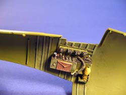
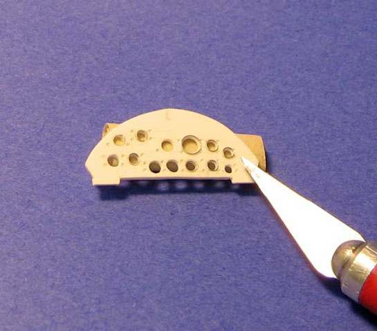
The final aspect of constructing the cockpit was the instrument panel my intent was to use the kit instrument panel but the total lack of detail and inaccuracy of the panel itself keep me from doing so. I decided to construct my own to at least resemble the basic true shape. After laying out all the gauges and drilling the appropriate size holes I created the gauge bezels from thin metal wire, wound around a tube cut and glued to the panel itself.
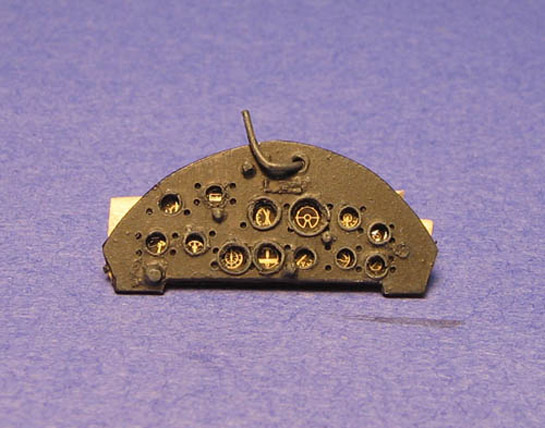
To represent the gauges instruments themselves I used the kit film backing this up by a thin sheet of brass to highlight the gauges with a thin sheet of plastic behind the brass to hold it all together. Then everything was painted a matt black.
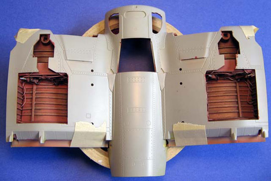
With the conclusion of the cockpit everything was assembled inside the fuselage halves glued and left to dry. The bottom half of the wing section that holds the floor would be assemble along with the center wing section and then mated to the fuselage later in the construction. Just make sure you continually test fit everything as you go along, you can always make any adjustment as needed. So with that I was heading into the center wing section, wheel wells and mating of the wing section parts.
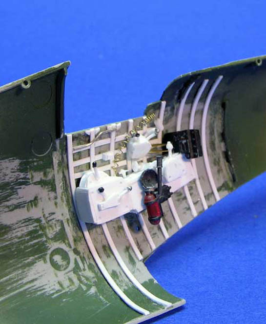
Wing and Center Section
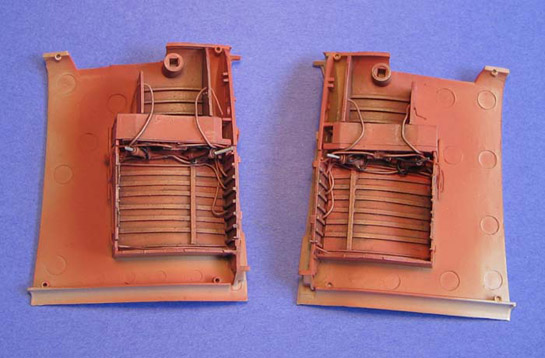
The kit wheel wells have some minor flaws, the mold injector marks are everywhere on the floor of the wheel wells. Using thin sheet plastic I constructed new floors for the wheel wells, and added the framing. I fabricated the hydraulic lines from .20 wires.
Paintings of the old F4U-1’s wheel wells are a bit different from the later model Corsair’s. A salmon color zinc primer was used; I mixed this color with red, white, zinc chromate, rust and yellow.
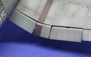
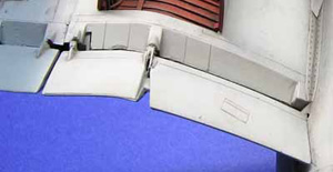
After the wheel wells were complete I moved on to the construction of the Flaps, it is required because of how the PE hinges are mounted between the top and bottom sides of the inner wing section. This area was a bit of a bad design on the Trumpeter kit. First, I don’t like moving parts, never have. And second, the alignment and fit of the flaps with the PE hinges are just way off leaving way too large of a gap at the top edge of the wing section. I compensated for this by not dropping the flap full down.
Also one note the copper wire hinge material is ok, but I did do one made out of plastic rod. I believe that this one was much easier, not as strong but it did hold just as well. Remember to melt flatten the ends of the plastic rod. If you test fit and use the plastic rod to can add the flaps at the end of the build
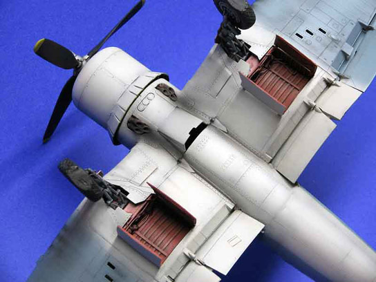
Engine and Cowl Flaps
The Engine is fairly straight forward I decided to use the Contact Resin Pratt And Whitney kit, with the -8 distributors and Magneto the only added detail to this was the inclusion of wiring detail and push rods to the front jugs. The kit It is very detailed, and included in the odd 57 piece set, there is enough to built three different versions of the P&W R-2800.
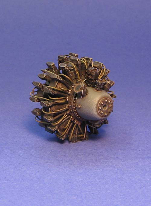
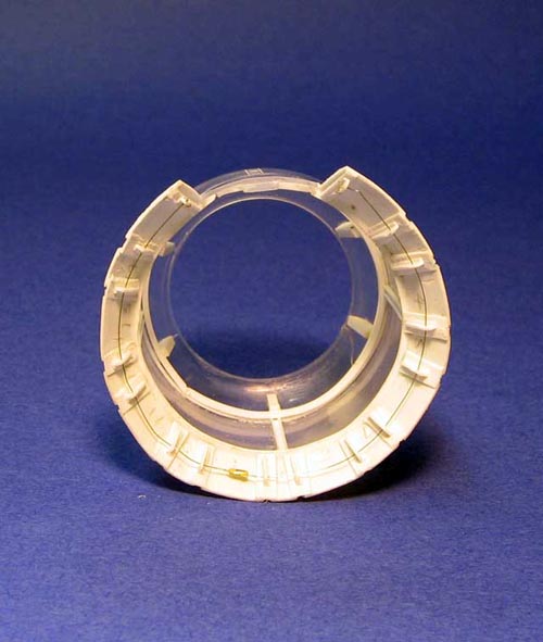
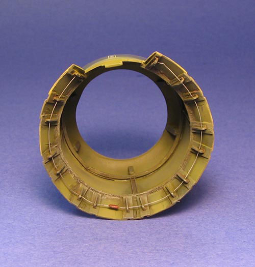
The cowling on the other hand was a complete mistake upon Trumpeter design team. With the kit cowling excessive gaps between cowling flaps it made it impossible to even use, I decide to scrap the kit cowling and fabricate a new one from Evergreen plastic. Making alternating large and small flaps with interconnections between them I followed from a previous design from Brian Cauchi and Chris Kirchhoff, with a twist of my own design added. I added 0.20 Wire as the flap control cable and tubing as the turnbuckle.
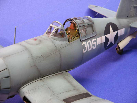
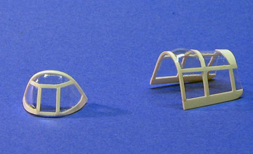
Canopy and Aft Fuselage Mod
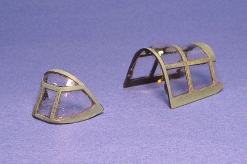
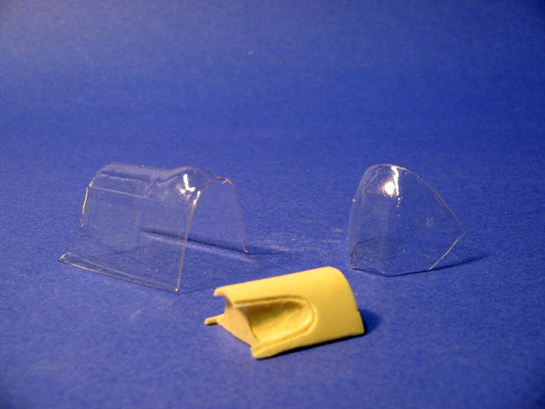
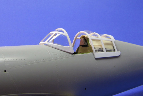
This part of the build I have to say was the most difficult section of the whole complete build. Lone star models are kind enough to supply both versions of the birdcage canopy, but the detail in the framing is a bit to shallow. Also the canopy will need light sanding and polishing before framing starts. I framed the canopy with .010X.060 strip evergreen plastic, inside and outside of the canopy, be careful with this step of the process I used the spare canopy to practice with.
I also tried a variety of glues and for me medium CA glue worked best. After the framing was dried I used a pin vice to add the details of the framing screws. Painting of the framing with flat black on the inside and Polly Scale USN blue gray outside was hand brushed on. Do your self a favor here just go ahead and mask the canopy inside and out and spray it I really thinks I took the hard road with hand painting the framing. But hey use your own judgment.
In addition to the canopy since we are really talking about the conversion here Lets go ahead and discuss the aft fuselage mod. The conversion set from Lone Star comes in a set and with the Vacuform canopy you will receive a cast resin aft fuselage deck plug. The resin plug is well made, but it does require some sanding to smooth out the resin this can be a bit tricky when trying to get inside the small “D” shaped aft window area. Just take your time and this will look great. A note on this when making your cut of the fuselage be careful the instructions show a line and shaded area to remove that is a bit low for the mod, cut shallow here test fit ,sand , and fit. Go slow and your result will be much better. I on the other hand cut a bit deep and had to add sheet plastic back in to build up the area.
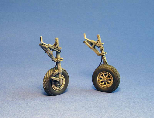
Landing Gear
The landing gear on this kit build was straight forward, I didn’t want to use the kit wheels while detailed they are a bit too thin. I decided to use a set of resin wheels and tires from Contact Resin; these were diamond tread for land based aircraft in World War Two, well worth the money. The only other thing that I decided to add to the landing gear was the inclusion of hydraulic lines and brake lines; these were constructed from .20 solder wire.
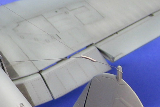
Antenna
The antenna wire detail was the standard Models By Murph addition of stretched sprue, the only difference with this one is that I added a wire spring made from very light gauge wire coiled into a spring.
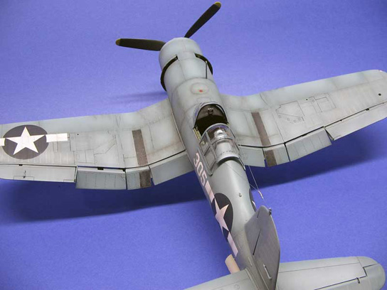
Painting
Paints used: Polly Scale USN blue gray, USN light ghost gray, flat black, flat white.
Painting of the Corsair followed my tried and true method; after all the final assembly was complete I polished all the seams and exterior areas that required buffing. I then primed the kit with gray primer tinted with Polly Scale USN blue gray. This allowed me to see any imperfections in the sanding, after re-sanding and buffing the areas that required attention I primed again.
I sprayed a base coat of light ghost gray to the bottom; added black to the base color shadowed the panel lines, added white to the base coat and highlighted the interior panels. The Top coat follows the lower painting much in the same way with excessive shades of highlight color touching up on the shadows as I go along.
A coat of future floor wax was applied, and then decals were added after the paint was dry.
A wash of black and rust enamels followed the acrylic painting, allowed to dry 24 hours and cleaned in a shrieking direction of the airflow.
Weathering was applied with pastel oils, and then the entire model was coated in Polly Scale clear flat.
In all I really enjoyed this conversion I really hope you enjoyed the article, so run right out there grab an F4U kit, then call Mike West at Lone Star Models and Go to town on this build. You’ll never regret it for a minute.
Thanks and have a great build.

© Damian Murphy 2007
This article was published on Wednesday, July 20 2011; Last modified on Saturday, May 14 2016