
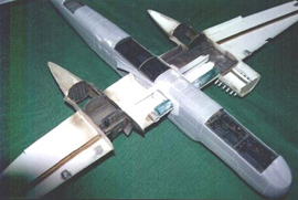
I.D. Models 1/32 Heinkel He 219
By Brian Cauchi
Introduction
Below is a description of some of the work involved in building the vacformed I.D. Models, Heinkel 219. It took me roughly 3 years to complete this model which was a sort of experimental build for the following reasons:
- It is my first vacform kit
- I tried out a new process whereas all the kit was constructed without painting any part beforehand.
I had obtained this kit from Doug Feeney himself (the big man behind ID Models, now retired). He had visited Malta a number of years ago and had written to me asking whether I wanted any model from his range. I had chosen the 219 since I thought it would be nice to have in my collection. It is also the kind of aircraft which is not normally built in 32nd scale.
As a first vacform, I don’t think it was a wise choice since the kit is hopeless and requires major reworking of all parts except for the fuselage which I found to be acceptably accurate. It is also a very difficult and large subject. (I am still trying to find a place at home where to display it.) Last consideration is the limited literature and details pertaining to this aircraft especially during the first two years of construction. This is no longer true because ever since Tamiya released their 1/48th model, a multitude of aftermarket stuff followed. A factor which outweighs all this heavily is the sheer beauty of the finished model.
Since I knew that it would be a long time before the model would be complete, I decided not to paint any part or section before constructing as much of the kit as possible. The whole model was therefore completed to a high degree including all minor details. I dry fitted the whole thing so that I assembled the whole model with tape before touching any paint or glue. What usually happens when I complete a section such as the cockpit and paint it is that by the time the model is complete, this would have been handled so often that it requires a repaint. I tried hard to avoid this and managed successfully.
As a guide, due to the relative scarcity of literature and the fact that line drawings from one publication do not tally with another, I bought a 72nd scale Dragon model. This I found to be very accurate except for the keeled ventral tray which needs flattening and rounding off. Some time after the Tamiya kit was issued, I borrowed it together with all the aftermarket products which were released by Verlinden, CMK and Aires. I braced myself for a shock since I had by now completed all detailed areas including interior, wheel bays, dinghy compartment, fuel cells and engine bay. To my relief I found out that all my detailing was correct to a T and tallied with the Aires detail set which is brilliantly accurate and the only one worth buying.
The only aftermarket set for the 32nd scale 219 is a detail set by Marine Air Products which is a mixture of sponge like resin and molten masses of white metal. I don’t know whether mine was a sample or the normal production set but boy was it bad. Although pretty extensive, the set required as much work as the basic kit and was a headache. The resin is very bad and highly porous, the white metal castings are beyond use and do not resemble anything they are meant to reproduce and to top it all, most parts are highly inaccurate. A number of the parts supplied were also broken.
The set included:
- A cockpit of sorts including sides, navigator’s instruments, seats, gun sight, front armored panel and joystick. Most of the items were modified and used. The side consoles were heavily warped and were greatly modified to an acceptable level. The seats were mostly scratch built and I only retained their basic shape. The joystick was broken and the top part was used.
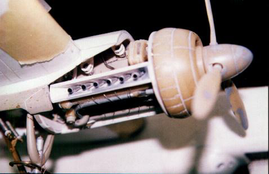
- Engine cowlings. These were retained, rescribed and hollowed out since they were solid masses of resin. The result was a couple of cowlings each made up of two separate parts. These were modeled on the Tamiya cowls which are highly accurate.
- Propeller spinners and blades. The blades had to be reshaped. However, these items were used.
- Wheel bays were highly inaccurate and discarded.
- A complete set of wheels were about the best thing provided and these were used after the multiple blowholes were filled in. With this set, this was a never ending process because as soon as you try to sand the filler, you unearth a multitude of new holes and so on.
- Undercarriage legs were masses of bent and distorted white metal which were immediately discarded.
- Also included were the supports for the radar antennae on the aircraft nose which were of the wrong shape for my particular model and were therefore not used.
Starting out
Being my first vacform, I tried to follow all the advice I’d heard from various sources. I traced around all the parts with a black marker and cut these out making sure that the marker remains visible. A length of sandpaper roll was pinned onto a flat strip of wood at least 1m long. All the parts were then held lightly and run over the sanding strip till the black mark just disappeared, making sure that even pressure was applied to the various parts being sanded. The different parts were tried together and sanded in particular areas as required.
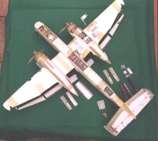
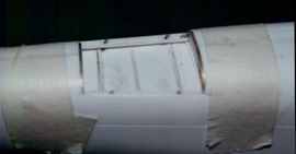
I then transferred all the panel lines from the dragon 72nd scale model onto mine following careful measurement and using a pen. The position of the cockpit opening and front wheel bay were marked only after all the panel lines were positioned correctly. I then went through the literature I had available and decided on which areas to expose. My choice fell on the dinghy compartment, the electrical equipment bay on the rear underside of the aircraft and the fuel cells top. The aircraft has three cells but I only had information showing the rear two and so decided to expose these.
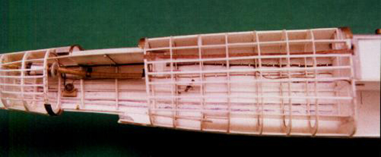
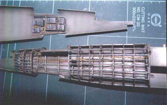
The relative panels were removed resulting in a very flimsy fuselage with gaping holes. I decided against fitting bulkheads till the individual detailed areas were complete. Most of these provided bulkheads and supports which would once again consolidate the fuselage. An edge made from scrap plastic card was created all around the fuselage perimeter on the inside so as to have a support when both sides are mated together.
Cockpit and Front wheel well
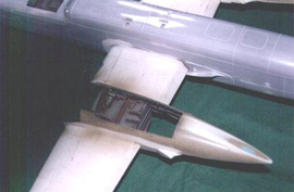
This was the first area to be tackled. The cockpit floor was made from plastic card. The underside of this is in fact the front wheel bay. This was fixed to one side of the fuselage.
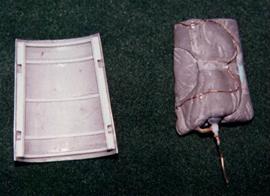
A resin bulge which formed part of the detail set was used and fitted inside the plastic card. This provided space for the wheel leg when the wheel was retracted. The sides of the wheel bay were then detailed. Details include the compressed air cylinders for the ejection seats and various pipes and wires including a couple of pressure gauges on the cylinder tops. One side of the bay would be impossible to paint following installation so that this was made separate and modeled to fit exactly in place once painted.

This aircraft poses an immediate problem. It has a nose wheel and no front beyond the cockpit. The cockpit floor is the front wheel well top and where does this all lead to? No room where to put weights for the aircraft to sit on its front wheel instead of its tail. So as not to waste precious space, I filled the very short limited nose space in front with lead shot. A large compartment was constructed immediately behind the radio operator’s position and this was also filled with lead shot. The first impression is that this is overdoing things and the kit weighs a ton. But in the end, it ensued that this weight was not enough and I even had to resort to fixing more lead weight under the seat. The resin sides were corrected for the various mistakes and omissions but at least they fitted in the allocated space.
The rear panel with a mass of equipment was also detailed and plastic added to its sides so that it would fit snugly into the fuselage. The instrument panel was scratchbuilt using plastic card and bezels. A mixture of 32nd and 48th bezels is normally required. The rudder pedals were mounted on their shaft and the joystick made up from the resin top part and aluminum tubing.
Next came the seats. The resin seats were modified and accurized. Some of the resin was replaced with plastic card. Head and foot rests were scratch built and the whole assemblies mounted on a scratchbuilt dividing frame which includes the rails onto which the seats slide since these were ejection seats.
Seat belts were made of masking tape and photo-etched buckles. This completed the cockpit. The weight compartment also provided support to the first third of the fuselage so that no additional bulkheads were necessary.
Dinghy compartment
This was constructed from thick plastic sheet. (extra plastic from the same kit) Incidentally, one really good point in ID models is the plastic used. It is thick and allows for easy scribing. You can also have a decent butt joint a good area for glue which will not come off easily. During the course of construction, this proved invaluable in many instances. What I can say is that all the extra plastic surrounding the parts has been used. The dinghy was made from Milliput. The compartment cover was made out of aluminum sheet. The compartment itself and cover were detailed with frames and the release mechanism. When the pilot pulled a lever in the cockpit, the compartment cover was released and at the same time, a compressed air cylinder activated. This automatically inflated the dinghy and pushed the cover away from the aircraft.
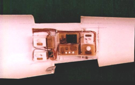
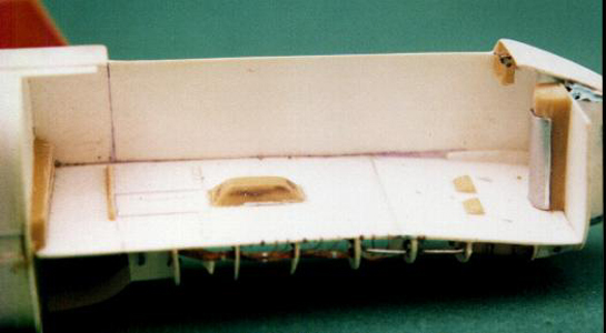
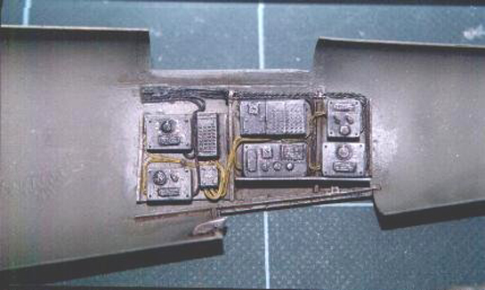
Rear Electrical Equipment Compartment
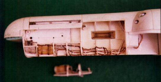
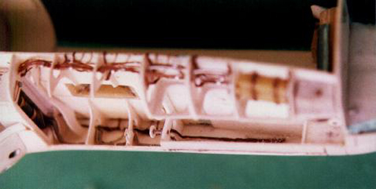
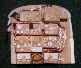
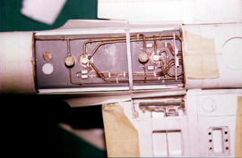
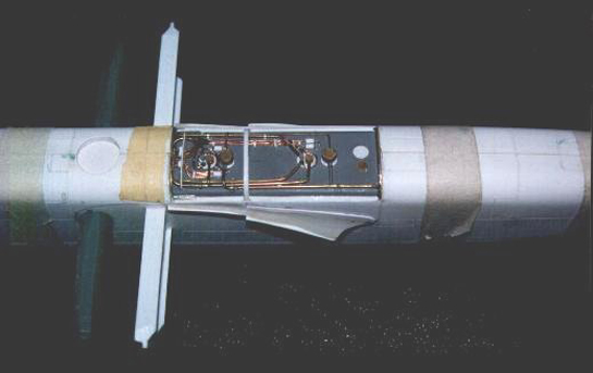
Here is one area which I over-detailed. Starting out from the rear electrical equipment bay, the whole internal structure up to the fuel cells was constructed. The initial idea was to open up a side panel. This I in fact did but it immediately became apparent that the fuselage would become too flimsy since the side panels are huge and run for most of the fuselage length aft of the wings. The panel was once again reinstated and in the end, only the bottom access hatch is opened offering a view of the electrical equipment and the fuselage heating unit. All internal structures were made of plastic sheet, plastic rod and aluminum tubes.
Fuel Cells
The fuselage sides were at this point taped together and the wing supports tacked. Due to the envisaged weight of the finished model and also due to the fact that the model’s weight would be supported by the wings, a strong support was required. An I section plastic beam was used together with a circular section thick rod. The rod was located at the wing leading edge and apart from offering support would also serve as a gluing surface for the part of the wing leading edge. The I-beam is located at the thickest part of the wing section and serves the same purpose. It was intended to run this beam to the main landing gear wells so that it would bear the weight but this was not possible following detailing of the wings and wheel wells.
Since I did not know what happened in the DF circular aerial section, I opted to uncover the two rear fuel cell tops and these were detailed using brass and aluminium tubing and wiring. The cell top was made from very thick plastic which allowed me to give it its rounded edge shape and also served as a support between the fuselage sides. The fuselage cover was made from aluminum sheet.
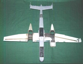
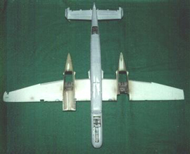
Wings
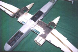
The shape of the wings as supplied with the kit are completely wrong and these had to be re-cut. One technique I used often in the course of building the model was to scan the 72nd or 48th part, enlarge it to bring it to 32nd scale and then print it. I found this to be very helpful with obtaining accurate outlines for parts. I used this in particular for the wings, tailplane and tail fins. The Ailerons and flaps were obviously cut out since these would be repositioned, the flaps in the lowered position. One wing was chosen to be detailed and this would have an exposed engine, and oil tank compartment, a cannon and the ammunition bays.
The wings are horizontal till the engine nacelles. The outer portion then has a dihedral. This was obtained by gluing a square section hollow copper bar which was given the desired angle. Thus, both wings had the same angle. It also served as a support. The engine nacelles supplied were of the wrong shape and these were built up with Milliput till the correct shape was obtained.
 The wheel bays were built up using plastic card and then detailed. Plumbing and wiring was installed and provision made for the eventual fitting of the undercarriage legs and supports. The engine bay was also detailed. I had to cheat somewhat here and create a thicker bulkhead than actually required to keep the wing together since this fell apart when I finished cutting up all the areas to be exposed. The gun and ammo bays were also built up from plastic card and detailed as required. The visible part of the cannon was scratchbuilt. Ammo chutes were made from sheet alumimium and the cannon shells were made from brass rod, turned on a mini-drill and sandpaper and cut off at equal lengths. These are then mounted on a think strip of masking tape which can be painted to represent the shell links. An actual ammo belt is formed in this way. The oil tanks were made from plastic blocks. All covers and wheel well doors were made from sheet aluminium.
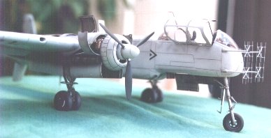
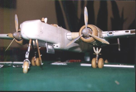
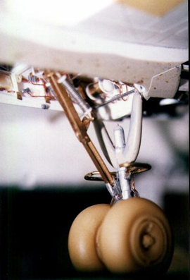
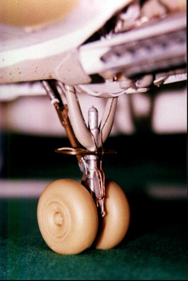
Main Undercarriage
The main undercarriage was completely scratchbuilt except for the wheels which were resin and formed part of the detail set from Marine Air Products. Since the total weight of the model would rest on these points, I decided to have them built completely from brass rod. I also got this bright idea of making the undercarriage work and so did not use any glue. All components were pinned together but his worked so well that it kept folding inwards so I finally had to fix the whole assembly by tightly pressing on the various pins. The main legs were then given a coating of Milliput and sanded down to obtain their unique tapered shape. The main supports were made from a brass u section and I section which as in the actual aircraft, fit into each other when folded. I was lucky in this respect to find components of the desired dimensions.
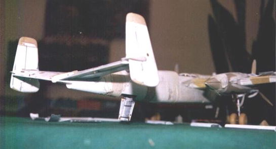
Tail Section
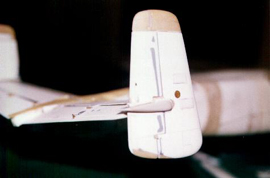
The kit part for the horizontal section of the tail was used. As in the case of the wings, however, this was cut to the correct shape, scribed and the elevators removed. I was lucky with the wings and tail section because the parts supplied were larger than required and so reshaping entailed cutting off extra pieces. Adding on plastic would have been another story. This assembly also has a dihedral and as in the case of the wings, square hollow copper section was glued to the lower part to obtain the correct and accurate angle. The upper faces where then separately glued in place. The vertical fins were very badly shaped. These were rebuilt using excess resin and the rudders cut off.
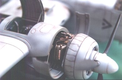
Engine
The engine was built around the Verlinden DB 601 engine. This was very generously donated by Saso (and originated from the Verlinden set for the Bf 109E). Extensive surgery was carried out on this resin product and after a few amputations and numerous additions, a beautiful DB 603 emerged, unfortunately to be mostly hidden by the engine bay when mounted inside the aircraft. This was mated to the heavily modified resin cowl supplied with the detail set. Additions include scratchbuilt supercharger, liquid coolant containers on both sides of the engine and lots of pipes and wires all over.
Canopy
The canopy supplied with the kit was suitable for an A5 or A7 model. This is markedly different to the A0 which I built. I therefore constructed a plastic master and had it vacformed by a friend of mine. Although not 100% perfect, it had to make do. The front and rear portions are very good and after lots of polishing are highly acceptable. The middle portion, however is not so smooth and this shows a bit.
Wheel Doors
The 219 main undercarriage doors are thick and include such details as a guide rail for opening. These were made from sheet aluminium coated with a layer of Milliput. This allowed for detailing and provided the required thick section.
Control Surfaces
All control surfaces were removed and rebuilt. Most were made from solid plastic and resin.
Painting
The aircraft modeled is He 219A-0, G9 + FB flown by Major Werner Streib on the night of June 11/12 1943. After destroying five RAF bombers, the aircraft was involved in a landing accident and was completely destroyed. Luckily, Streib survived the crash when the cockpit section of the aircraft was detached from the rest. Unfortunately, the quality of the photos is very bad and the camouflage is not clearly shown. Some sources even show the aircraft in an overall RLM76 scheme without mottle. However, after studying many photos of night fighters with similar schemes, I felt that there was RLM75 mottle present but this is not heavily applied and would not show in bad light or in a bad quality photograph. Much practice was carried out to obtain the required effect and after spraying most plastic items in the house, I was satisfied.
Since this particular aircraft was not flown on many missions before being written off, I did not go overboard with weathering this time. Due to the complexity of the camouflage scheme, I could not follow my usual painting pattern to fade the paint and enhance panel lines and so I opted for pre-shading. I did not fade any paint since this would call for extreme weathering so I just used black and pre shaded all panel lines.
Testors and Humbrol paints were used throughout. Metallizer paints were used on the exhaust shrouds, the engine and all hydraulic actuators on the undercarriage. I sealed in the metallizer paint with Revell gloss varnish. Please note that this works beautifully and does not diminish the quality of the finish. The metallizer sprayed parts will remain very much like true metal parts. If you use the Testors sealer, this effect is ruined.
Insignia
Decals were used for the swastikas on the tail fins, G9 codes, commander’s chevrons and the letter B in the code. All other markings are sprayed on including the black outlined green Fs.
The above is intended to give an idea of the work involved in completing the model. When one considers that it took three years for me to complete, I have not even started explaining what the work involved. However, I’ll be happy to help anyone with particular queries.
© Brian Cauchi
This article was published on Wednesday, July 20 2011; Last modified on Saturday, May 14 2016