
3D Printed 1/18 P-51B-10A "Cripes a' Mighty"
By Jay Wheaton
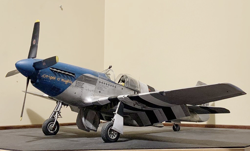
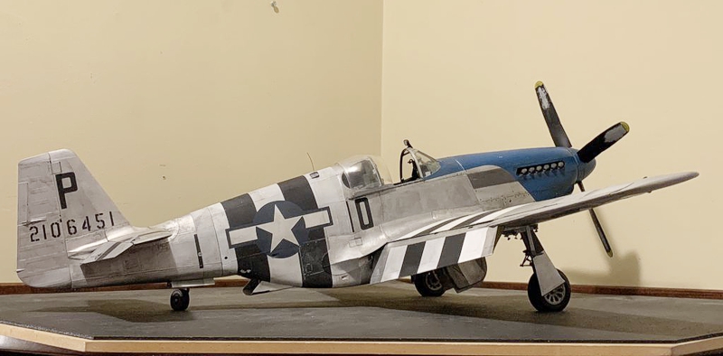
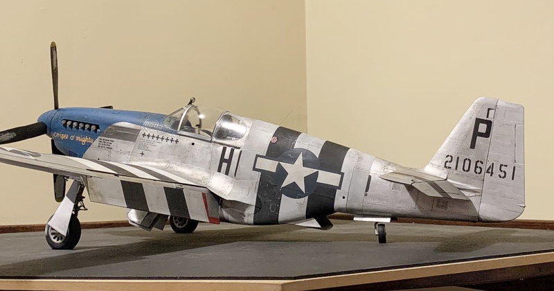
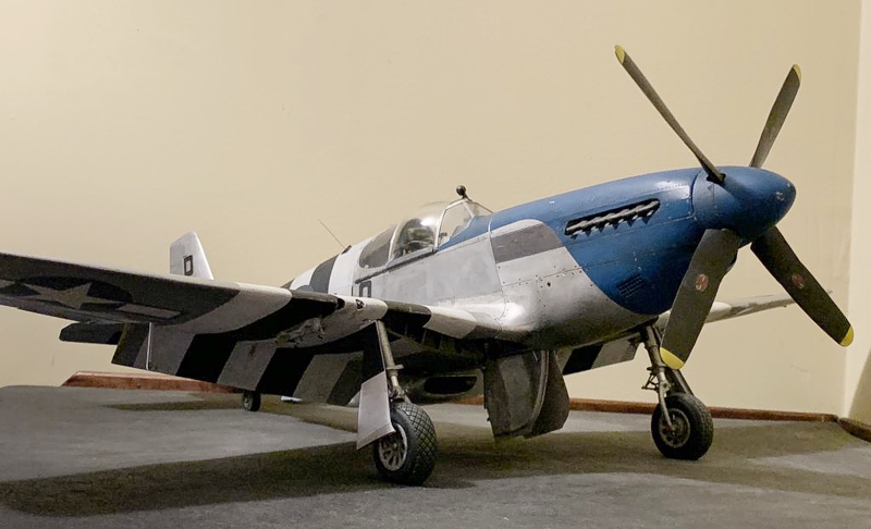
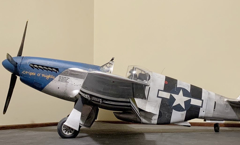
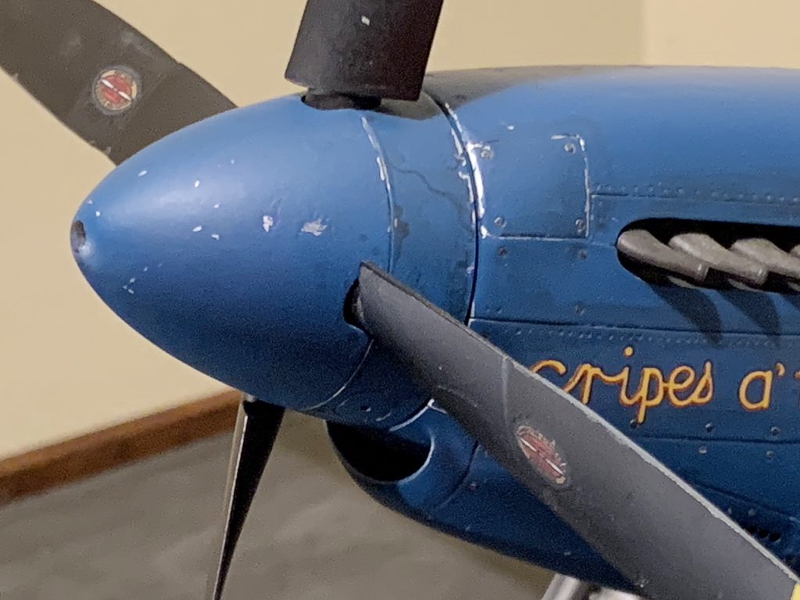
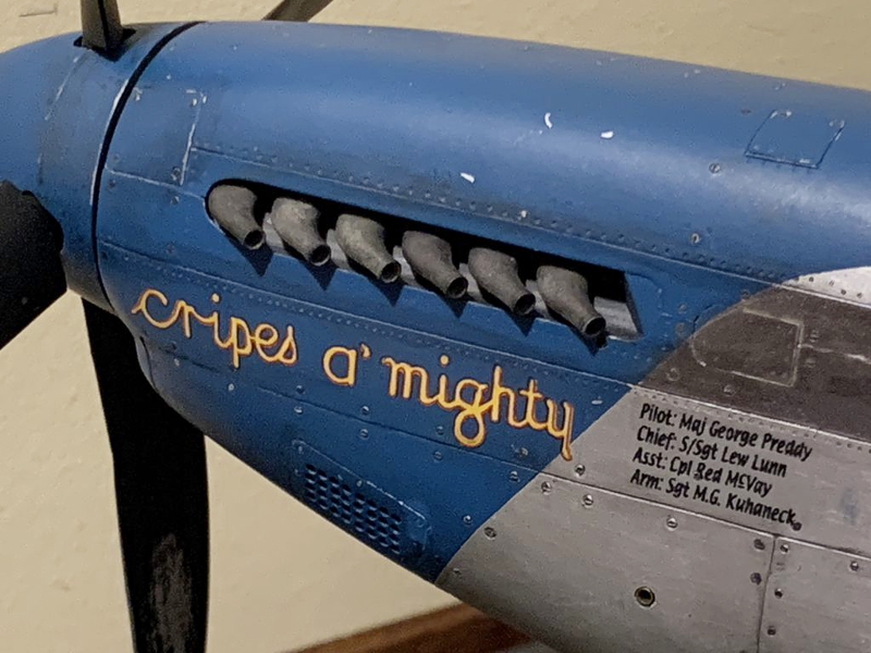
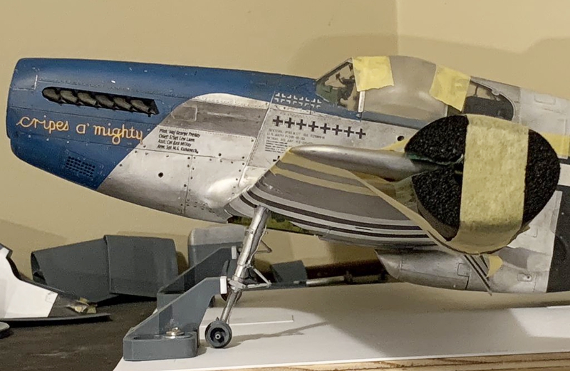
I would like to present to you my 2-year long project "Cripes a' Mighty" P-51B-10NA Mustang, flown by Major George Preddy of the 352nd FG ("Blue-Nosers"). The scale is 1/18 - she is a big girl for sure. She is about 99% 3D printed using an Elegoo Saturn 2 printer. All components were designed in Rhino 7, using original NAA engineering drawings obtained from the Aircorps Library. The construction can be found here in my build thread in the Works in Progress forum.
Some comments on the build:
First, the reason I picked this subject (a P-51B) was mostly two-fold. One, I really wanted to do a Malcolm hooded, natural metal finished -B model. And two, the P-51 is just about completely defined by micro-filmed engineering drawings available from Aircorps Library. That, along with learning Rhino 7, and purchasing a good 3D printer, allowed me to produce a model with near perfect dimensional accuracy. That applies not only to the fuselage, wing, and tail, but also every detail I chose to include. Hardly any guesswork. Hardly any errors. As for the selection of "Cripes A' Mighty" - well that was mostly from a vote by many of those who were following the build, and my concurrence. There were other great subjects to choose from; Cripes won out.
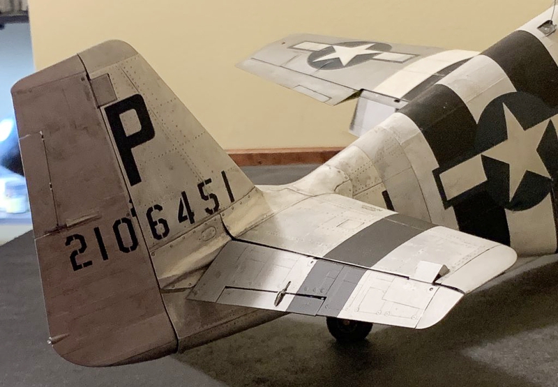
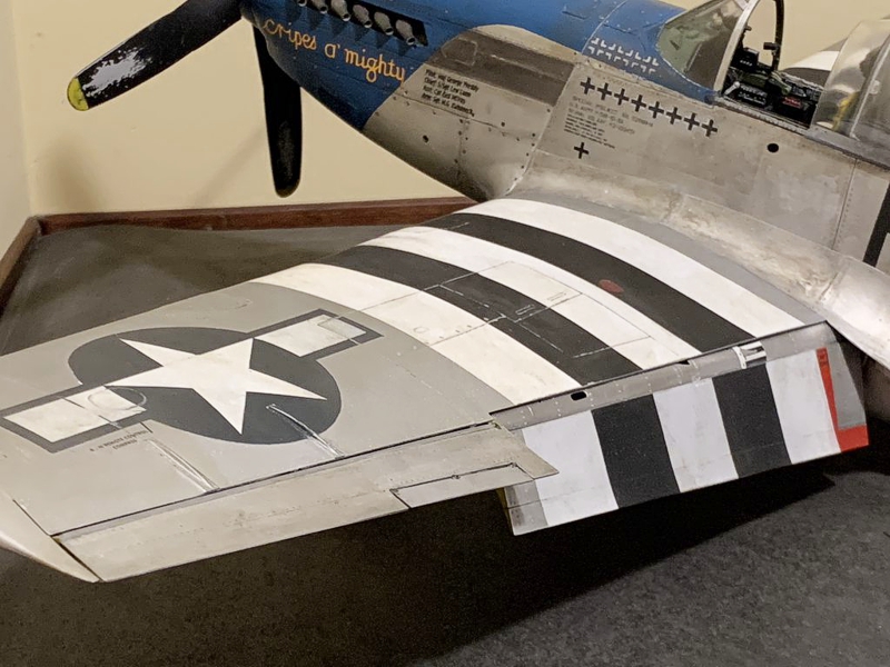
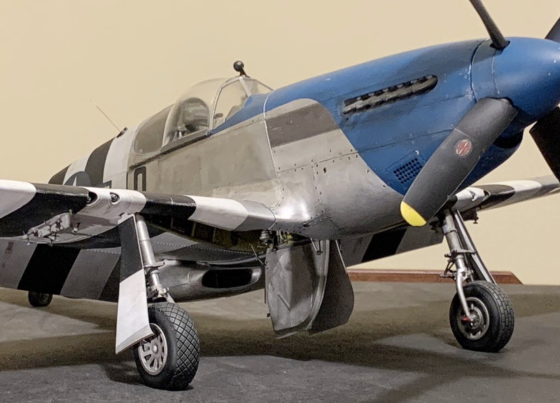
This was my first effort at building a model totally by 3D printing, with absolutely nothing to start from. And what a learning process it was. 3D print resin is amazing stuff, but it is fragile. I cannot count how many times I broke a part and either had to repair it or print a new one. But when done properly, the results are details that often cannot be obtained from plastic, or even scratch building. As a result, Cripes is the most realistic model I have ever built. I would also add she might be the most fragile model I have ever built. Not the basic model - it is super-stout. But little things like wing tips, gear doors, mirror, etc. And this is my second effort at aluminum skinning using .005 inch thick aluminum sheet. Not easy to do, and it can be very tedious, but this process can result in a very real-looking natural metal finish. I learned this technique from Peter Castle - we know him as Airscale. He has been doing it for years.
This project was a mix of elation and pride - why we build models - and panic/anger/fear/frustration. Cripes was not an easy build. And big mistakes were made (all were ultimately fixed). How about mislocating the flare gun hole one full bay and royally screwing up the left-hand cockpit sidewall. Or putting the three colored ID lights on the wrong wing. Or screwing up the main landing gear rake angle by a couple of degrees. Or a huge one - tipping it over late in the build and breaking off the centerline gear doors and the left hand landing gear strut. OMG that was awful. There were painting disasters, disbond issues, fractured parts too numerous to count. But there were also moments of huge victory and accomplishment and pride.
I think perhaps the most interesting and successful element of this build was the use of a 3D printed highly accurate fuselage assembly jig, designed by myself. Here is a picture of it:
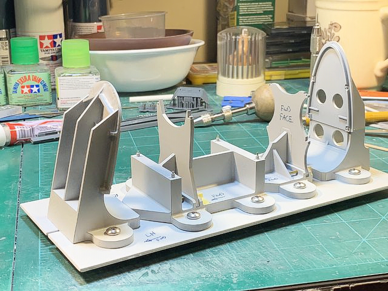
The bulkheads in front and back slide in slotted holes to allow the longerons to be loaded. With some fuselage parts loaded onto it (four longerons, and many frames):
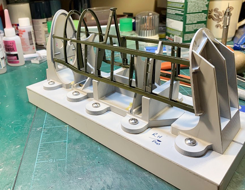
I show this because this jig provided the foundation for the entire build - an accurate forward fuselage with cockpit, and accurate attach points for the wing, engine cowling, and aft fuselage. Had to have that before everything else.
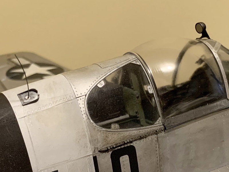
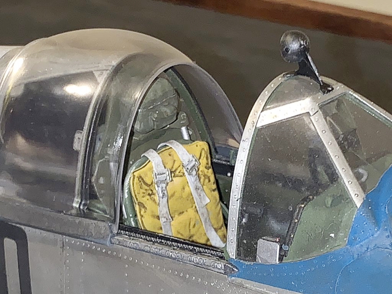
Another interesting element of this build was my decision to use 3D printed transparencies as opposed to vacuforming. Injection molded parts were of course not an option. Ultimately most (but not all) the canopy and windshield and aft window parts were provided by Shapeways at high prices, after I just flat failed on many of those parts. The concern of course was clarity. Most of the followers of the build were very skeptical of 3D printed clear resin to deliver. I will let you judge for yourselves.
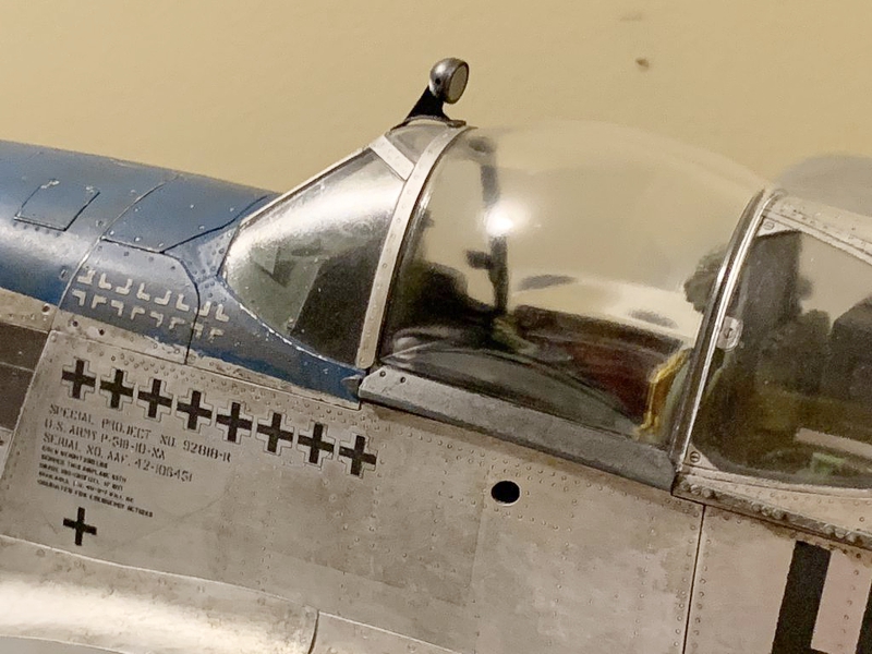
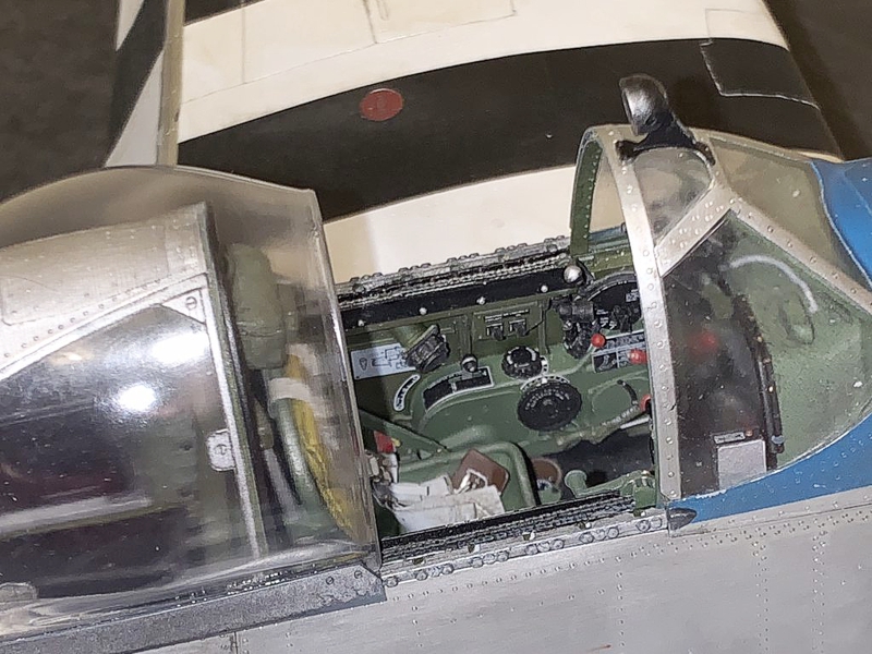
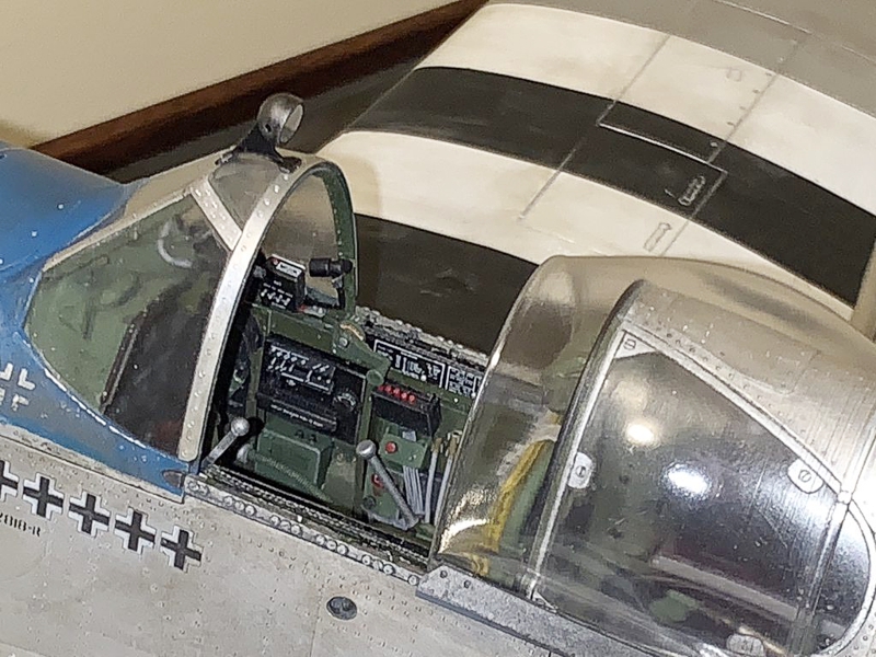
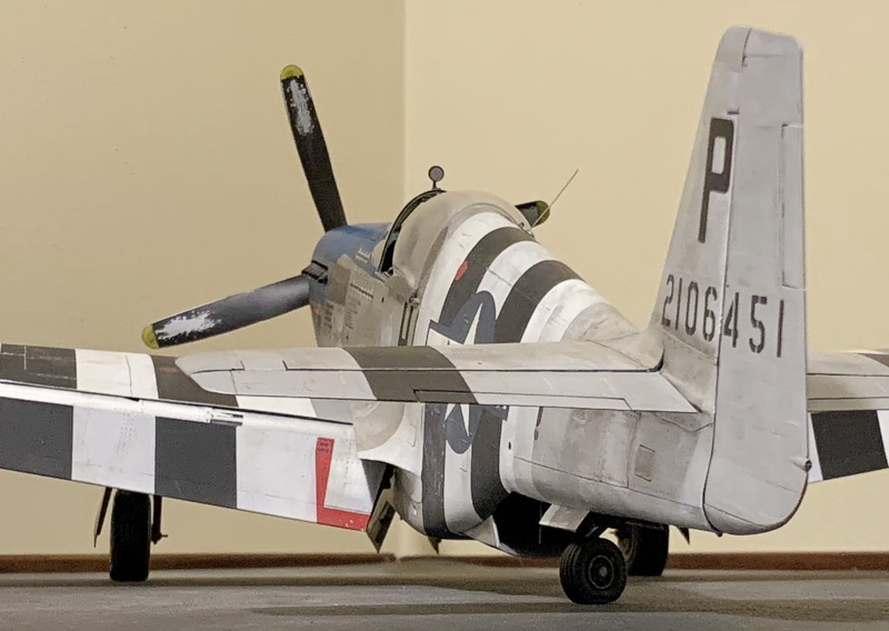
The area where I had to do some serious guesswork was the Malcolm hood and the cockpit modifications for same - there are no drawings or other specs. Dozens of pictures both period and from restorations helped immensely. During that time of the build, I learned a whole lot about the Malcolm hood modification, and how involved it actually was. ome of you may not be aware that the Malcolm hood was a field modification entirely. A -B or -C (or even an -A) model would go into the field hangar, and several days and hundreds of man-hours later, it emerged with a big fishbowl sliding hood replacing the greenhouse style canopy found on production aircraft. The mod was a big deal - major surgery for the cockpit. Pilots absolutely loved it, as seeing was life (along with speed and fire power). Visibility with the Malcolm hood was superb. At any rate, the hood was driven by a crank handle and chain drive. I am not aware of any modeler other than myself attempting to model the various cockpit modifications for the hood. Look for that in the pictures.
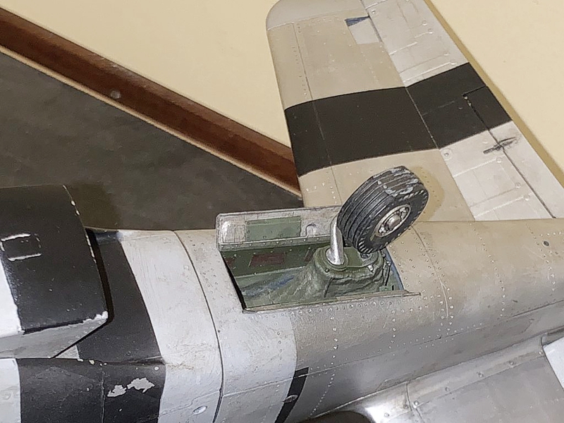
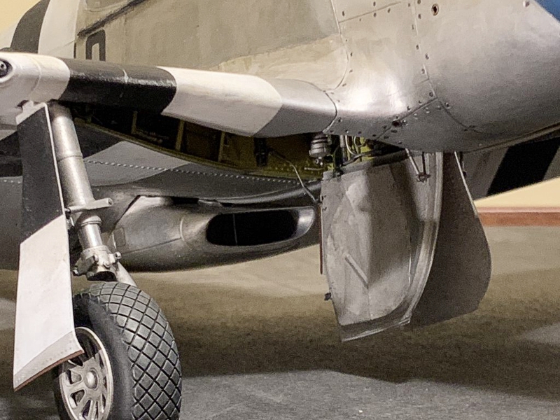
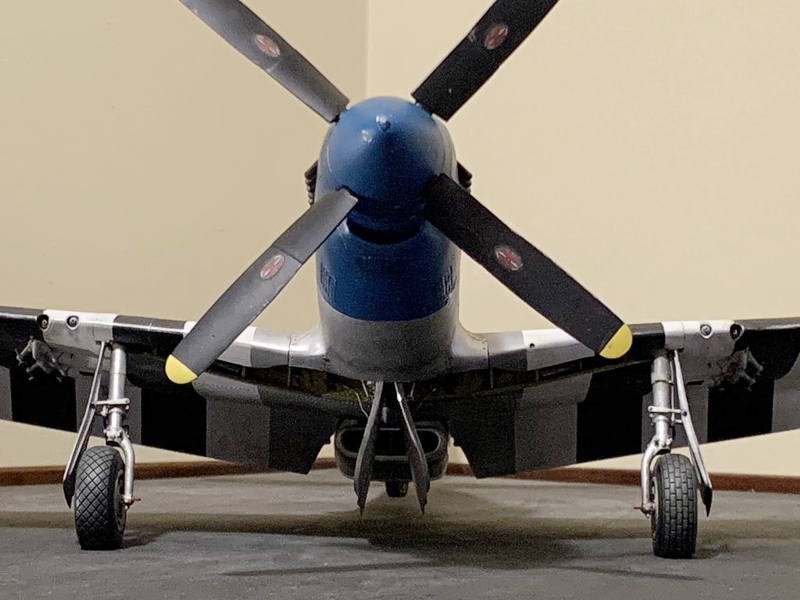
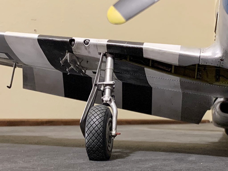
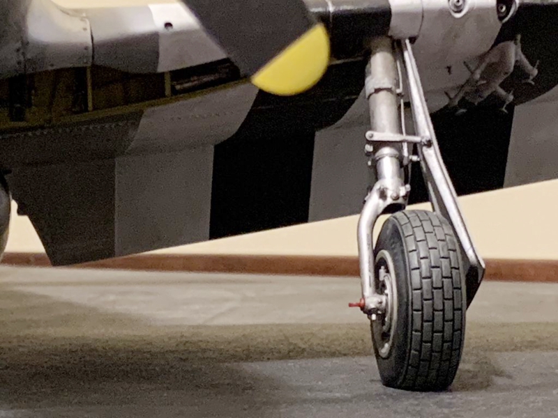
This model is heavy - about 2.5 pounds or so. Therefore, the landing gear struts needed help, especially the tail gear. This was the first time I reinforced landing gear struts with metallic rod (brass or music wire steel). Here is a picture of the tail gear strut and an internal stiffening rod formed on a 3D printed forming block of my own design:
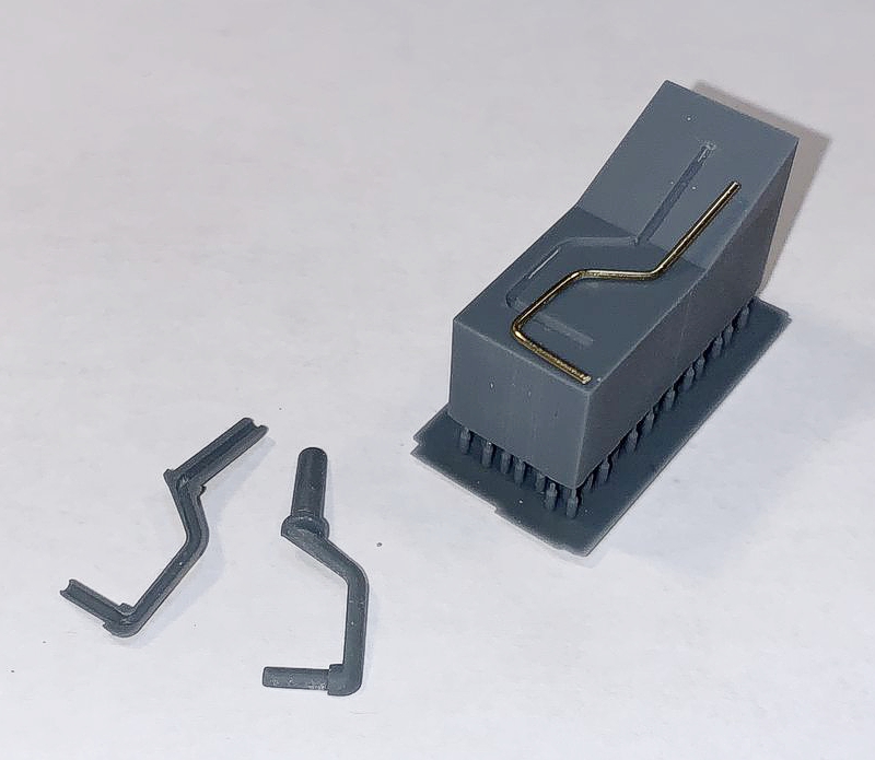
The main gear struts were reinforced similarly. The reinforcements have worked.
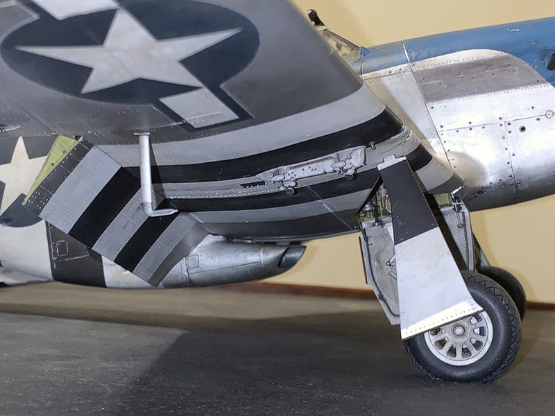
To my horror, after the main gear were installed onto the airplane, I discovered the rake angle was off by a noticeable couple of degrees. That after being so careful to design it right. I still don't know what happened. So, I created a fixture where pressure could be applied over days to the gear struts via shims with ever-increasing thicknesses, to gradually force the struts back to a correct rake angle:
See the white shims? I show this because it was some of the most stressful days of the build - hoping to get some permanent deformation on very stout gear support parts without breaking something important. Believe it or not - it worked! The hope of course is that it stays that way.
Lastly, some details to look for in the pictures:
- Mismatched tires (you see alot of that in period pictures)
- 3D printed chains nested in the upper longerons, which drive the Malcolm hood
- 3D printed clear transparencies
- External rails and rollers for the Malcolm hood
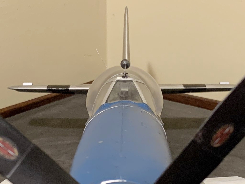
- Spitfire-style exteral rear view mirror
- Malcolm hood that can actually be slid fore/aft (if very careful)
- Movable tail surfaces
- Head rest pad and seat back pad (thank Antonio Argudo for that!!)
- The crazy shaped bomb racks
I would like to thank first of all the 40 or so followers of my build thread. All were very patient and supportive during the 2-year effort. And special thanks to Airscale for giving me the extensive decal set for his 1/18 P-51C Lopes Hope, hundreds of pictures, and a few helpful Rhino files. Oh, and the 1/18 scale seat belt hardware. Also Antonio Argudo for designing some really great models for me - the head rest, seat back cushion, and tail gear bay canvas cover. Also Thunnus who provided me with nose art decals and stencils, and stencils for other things like squadron buzz letters, tail serial numbers, national insignias, and kill markings. Also TAG and Antonio for priceless period pictures of anything and everything P-51B. And lastly Aircorp Library - OMG. Their collection of engineering drawings and other documents is absolutely priceless.
I hope you like Cripes a' Mighty. She is not perfect, and she appears rode hard and put up wet. But it is the best I can muster! Thank you.
© Jay Wheaton 2025
This article was published on Saturday, August 16 2025; Last modified on Saturday, August 16 2025