
Lindberg 1/32 Laird-Turner Meteor
By Martin McClendon
Background
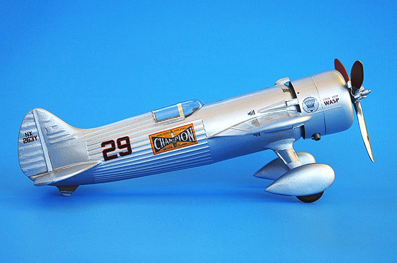
Col. Roscoe Turner was one of the most colorful figures of the golden age of air racing. His showmanship and early use of sponsored product placement made him stand out, but also to some extent obscure for us today just how good a pilot he was. His most famous publicity stunt was of course his pet lion, Gilmore, who often accompanied him aloft, and had his own custom parachute—at least, until he got too big to take into the cockpit. In a sport where a split-second mistake could mean disaster, Turner was able to stay on top through skill and pluck.
According to aviation author Kenneth Wilson, the Laird-Turner Meteor design originated in 1934 when Turner approached Prof. Howard Barlow, then working at the University of Minnesota, about designing a brand-new racer. Barlow was a pioneer in aerodynamic design and stress testing. He had previously worked on the famous Wedell-Williams racers, one of which Turner owned and raced. The Meteor design underwent several modifications and construction switched between different shops as Turner became dissatisfied with the original builders. The plane was ultimately finished by “Mattie” Laird’s shop in Chicago in time for the 1937 Cleveland races. Though he didn’t win the Thompson that year, he flew the Meteor to victories in the 1938 and 1939 races. Including two wins in the Meteor, Turner is the only pilot to have won the Thompson trophy three times. The races were suspended during the war years, and when they returned, they were dominated by surplus Mustangs, Lightnings, Corsairs, etc. The era of the custom-built racer was over.
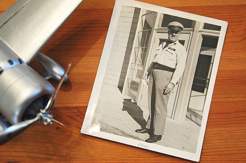
I have a personal connection to the story: Turner retired from air racing after winning the 1939 Thompson trophy, and started an aircraft services business in Indianapolis. That same year, my grandfather Clarence completed the mechanic apprentice program at Purdue University Airport. He got a job with Turner’s company as a mechanic, ground school instructor, and master parachute rigger. He also had the very cool job of doing annual maintenance on the Meteor to maintain its airworthiness certificate. Clarence left Turner’s company in 1942 to work for the CAA as the USA geared up to fight in World War 2. In later years, Turner continued to be a well-known and flamboyant figure but the golden age of air racing became just a nostalgic memory. He died in 1970, and a few years later his widow donated the Meteor to the National Air and Space Museum. It now resides in the newly-renovated “Speed” gallery of the NASM, as a fantastic example of the unique elegance of 1930’s aircraft design.
My family connection to Turner means that I have always been interested in his aircraft. In high school I built the Williams Brothers 1/32 kit of Turner’s Wedell-Williams “Gilmore” racer, as well as their 1/72 kit of the Boeing 247-D, in which Turner placed third in the MacRobertson Race from London to Sydney, Australia. I have been building plastic models since age 10 or so, but as I grew older and started a family, I had to turn my attention to other things. Recently due to the pandemic (and a mid-life crisis), I decided to get back into the hobby. I was inspired by several online articles detailing builds of the Lindberg Laird-Turner Meteor kit, and decided to build one and present it to my dad in honor of his father. The kit is readily available on eBay, and I purchased one for about $8.
The Kit
According to Scalemates, the kit debuted in 1959. An article at oldmodelkits.com details its origins with the Pyro company, an early pioneer of injection molding. As such, the kit is a relic of a bygone era, half model and half toy, featuring moveable control surfaces and an electric motor to spin the prop (the current version is not motorized).
My kit was from the Lindberg 2007 reissue, molded in soft white plastic. General fit is surprisingly good, and the fuselage has delicate raised panel lines and rivets. However, the kit’s forward section and cowling are not accurate in shape. It has too much ribbing on the tail control surfaces, the ailerons and flaps have ribbing when they should be smooth, a tiny out-of-scale pilot, fanciful cockpit details, and a crude rendition of the Pratt and Whitney twin-row Wasp engine molded into the inaccurately-shaped cowling. The propeller, undercarriage and wheel spats are reasonably accurate in size and shape. Decals look to be of good quality but are not accurate in terms of size and colors. Vestiges of the model’s origins as a toy include an odd hatch along the upper fuselage (for battery access) and a tailwheel (the actual Meteor was equipped with a tailskid). The original Pyro box art seen on Scalemates shows excited kids chasing the Meteor model down the sidewalk as its motorized prop scoots it along—hence the need for a tailwheel!
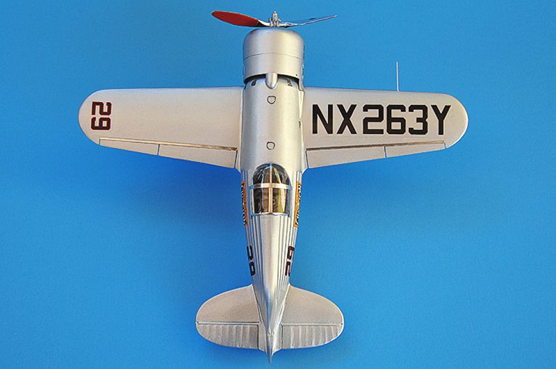
Comparison of the model with scale drawings done by Paul Matt reveals that the fuselage is several scale feet too long, and the wings are also too wide and too long. The diameter of the main fuselage is a scale 8 inches too wide. The wings have a straight leading edge (the actual wings were swept back slightly) and are canted with the leading edge up at quite an angle, as opposed to the actual aircraft in which they are close to parallel with the center line of the plane. After examination, I started to wonder how I could possibly create anything remotely resembling the actual aircraft with this kit.
Construction
Faced with choices about the kit’s inaccuracy vs. how much skill (or hubris) I possessed in thinking I can still make it look presentable, I began to form a plan of action for how to address the more obvious problems. I decided to try and scratch-build new components using a 3D printer. Ever since I was a kid, I have dreamed of being able to make models of anything I want, and the affordability of current 3D printers brings this dream a step closer. A vital part of the plan was the assistance of my son, whose understanding of 3D design programs was essential in coping with some of the more complex shapes.
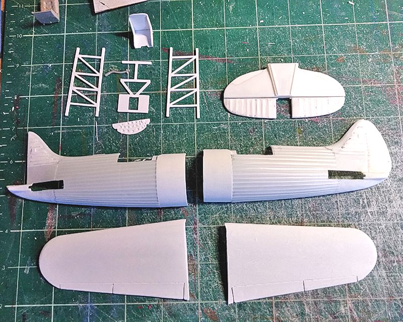
I decided to keep the kit parts for the rear half of the aircraft, where the unique fuselage shape and simulation of fabric over stringers were fairly accurate (and would be very hard for me to effectively design for printing) but to basically discard the rest of the model from the instrument panel forward (except for the landing gear). Rather than scratch-build a more accurate twin-row Wasp engine and better-looking propellor, I bought and raided the Williams Bros. Seversky P-35 kit for these parts.
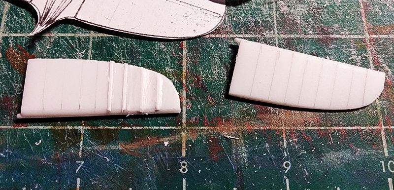
The horizontal and vertical stabilizers were trimmed and reshaped according to plans which I printed out to scale and used to trace the new shapes. Milliput was used to create the gently curved form of the leading edge of the horizontal stabs and trailing edge of the rudder, and I superglued scraps of PLA strips on the now smooth-sanded control surfaces at the correct locations to create more accurate ribs. Then I used multiple applications of “Perfect Putty” thinned with a little water to create the “fabric” over the PLA ribs.
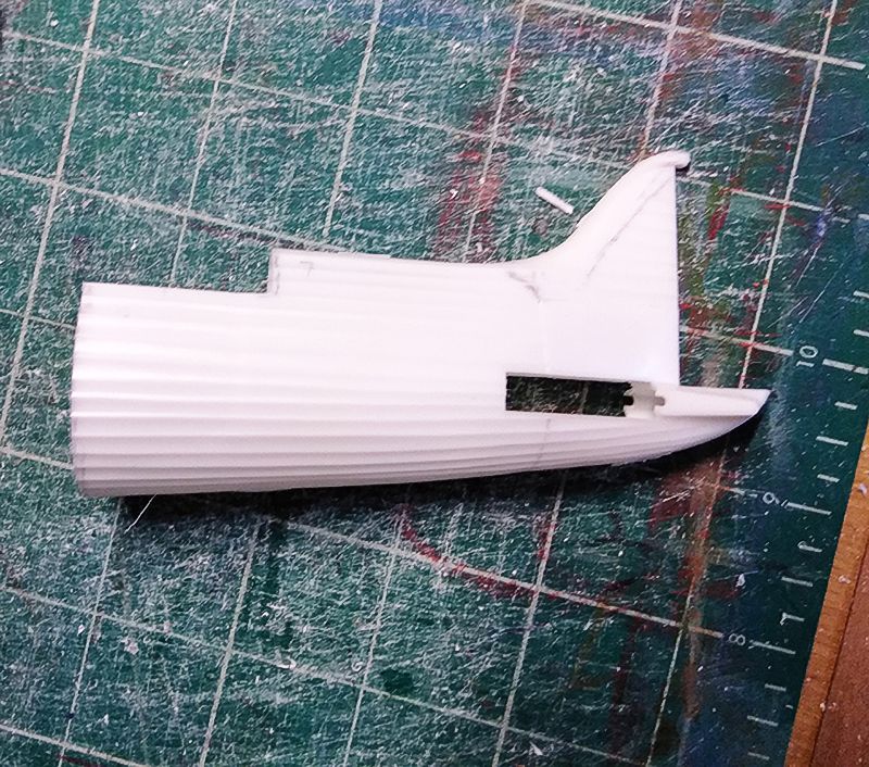
A fine-tooth saw was taken to the fuselage, cutting the entire front section of the model away, and relocating the rear cockpit bulkhead further back. Lastly, to accommodate what will be a slimmer forward fuselage, I trimmed the bottom edges of the rear fuselage to taper more narrowly from the tailskid to the cockpit. This did create un-evenness in the gluing up of the fuselage but allowed for the horizontal stab to be installed without further fuss, which I felt it was the least invasive way to manage the transition.
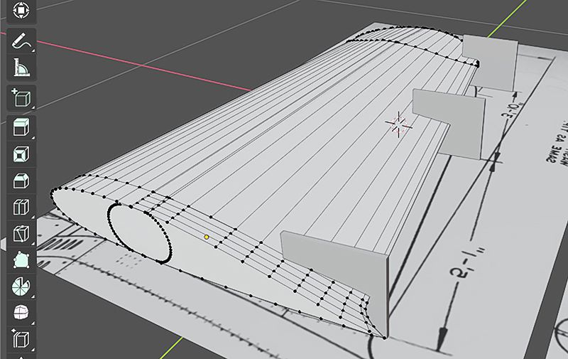
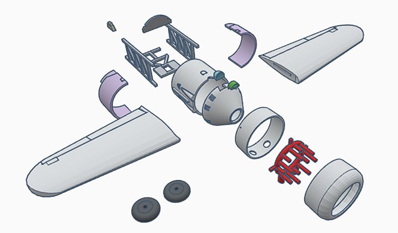
I used free design programs TinkerCad and Blender to create 3D models for a new forward fuselage and wings. TinkerCad has a relatively low learning curve: it works by intuitively drawing shapes of specific sizes and joining or subtracting from them. The finished shapes are then downloaded as STL files, compatible with 3D-printer software. I’m pretty good with TinkerCad, and was able to fairly quickly create the cylindrical forward fuselage and conical engine mount. But I needed my son’s help with Blender, where we modeled the more complex tapered airfoil shape of the wing. We then exported it to TinkerCad and sliced it into top and bottom halves to allow for easier 3D printing. The halves were then glued together with 5-minute epoxy. I printed all the parts in premium PLA plastic from Matterhackers. This plastic prints well and is hard and strong, even for small and thin pieces, but is a bit more difficult to cut and shape than styrene. You must use superglue or epoxy in order to bond PLA parts.
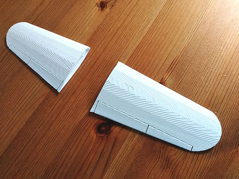
I used a Creality Ender 3 Pro printer, a consumer-level machine whose low price is the result of a very no-frills product. Unlike more expensive printers that are shipped complete, the Ender 3 Pro must be assembled and calibrated by the user. Lots of trial and error was necessary to perfectly align the build plate with the printer head, but once this was done, the resulting models can be extremely accurate and highly detailed. This is a fusion-deposition printer, which extrudes layers of plastic that build up into the desired shapes. The process leaves lines between layers, especially noticeable when printing complex curved objects such as the wings. I tried to speed things along by sanding these out with an orbital sander, but the sander overheated the PLA and melted it, damaging the delicate trailing edges. I printed a new wing and lightly sanded away the most obvious layer lines, and filled/sanded the surfaces with multiple coats of water-thinned Perfect Putty to hide the extrusion pattern. This took many hours of designing, printing, re-printing, and multiple passes of filling/sanding.
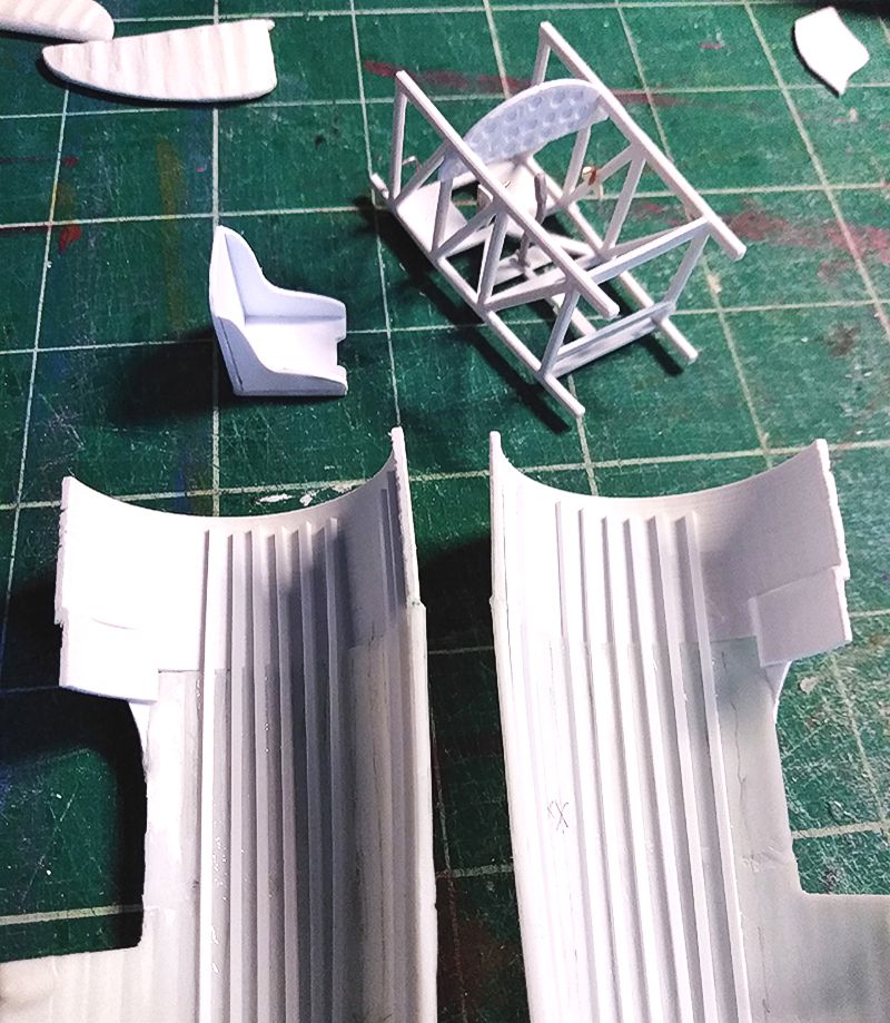
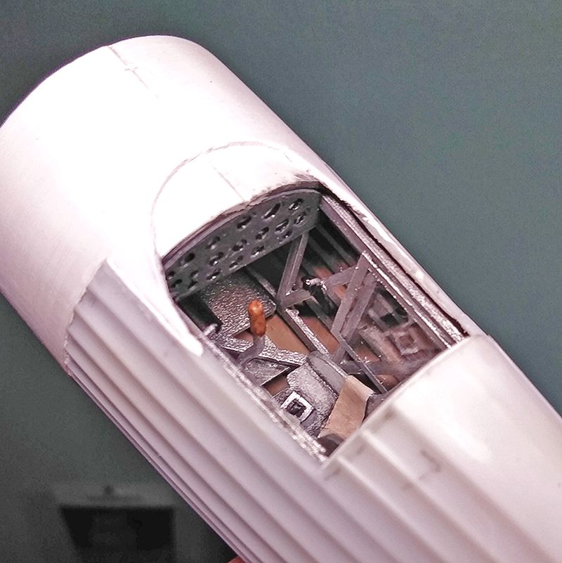
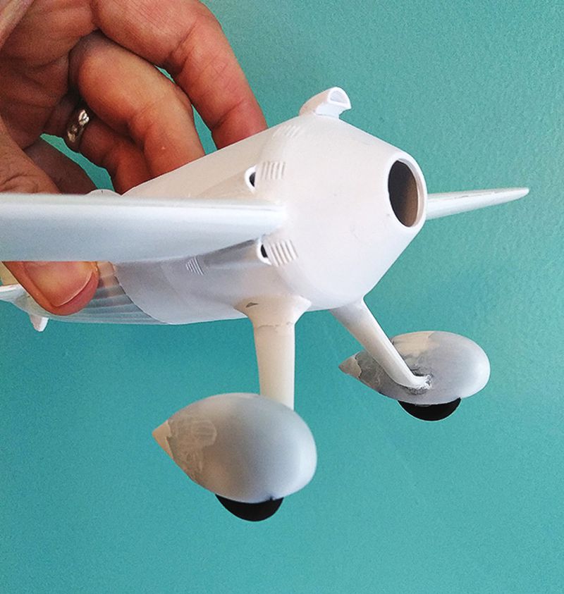
I divided the fuselage into several sections for ease of printing and assembly. The rearmost section was printed in left and right halves and superglued to the existing fuselage halves, allowing me to install Evergreen strips for stringers, paint out the interior, and test fit the cockpit. Then two small triangles of sheet styrene were glued on either side of the windscreen location, to complete the look of the sheet aluminum transition at that spot. The two oil cooler scoops on the right side that are missing in the Lindberg kit, as well as louvers and fuel caps, were printed directly into the new pieces. I also printed a new carburettor intake scoop that more closely resembles the real thing.
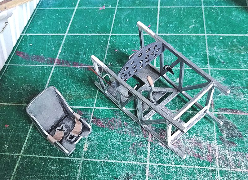
Kenneth Wilson’s plans gave details for the welded tube structure of the fuselage, so I printed the tube walls and floor, as well as a generally accurate instrument panel for the cockpit. Panel and coaming were painted Tamiya dark grey. I painted the round recesses in the panel black, and then used a pin to scrape away some of the paint to make white markings on the instrument faces. These were then filled with several layers of Pledge acrylic floor gloss to simulate glass. The simple aluminum seat was scratchbuilt from plastic card with a wine-bottle foil lap belt. The throttle and flap levers were made of wire and bits of sheet styrene, with globs of craft glue for knobs. The control stick was taken from the Seversky kit. Its shape is not quite correct, but I like how it looks. The cockpit cage was completed as a separate unit to be slid into the fuselage from the open front end. The interior sides were painted a light brown color (Tamiya flat earth and white) to simulate doped fabric.
The canopy of the original plane opened by splitting down the center, with the two halves dropping down into channels on either side of the cockpit. I used scraps of clear plastic sheet to create the two squares of the canopy sides, and glued them in the open position—down inside the cockpit.
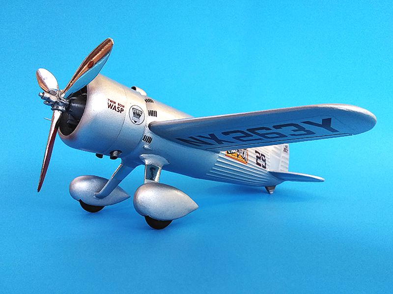
The landing gear needed help to get to “acceptable.” First, I cut off the inner wheel pant halves molded onto the struts. The struts attach far too high up on the pants—they should be level with the wheel axles. I trimmed away most of the plastic at the top of each strut with a sprue cutter, and using my scaled-up drawings to get the correct angle, glued these onto the front fuselage, and created fairings from Milliput and white putty. The kit wheels are too thin, so I printed new wheel halves with a more accurate blank plate mounted over the hubs. They were painted and installed in the pants after painting the interiors dark gray, and the pants were glued together and had seams sanded and puttied. I used Milliput to give a sharper rear contour to the backs of the pants; the kit pants are too rounded.
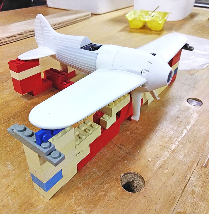
I slid the cockpit unit into the now-assembled rear fuselage, and superglued the various parts of the forward fuselage in place. Next, I needed to epoxy the wings to the locating tabs I had printed into the fuselage. Unfortunately the tabs were too wide and had to be laboriously filed down. The wings have a 3-degree upward angle to the tips. I made a jig out of Legos to hold the model and the wings at the right angle while positioning them. I used 5-minute epoxy which gave me plenty of time to get everything just right. The wing joint needed only a minor application of white putty.
I printed the tailskid and installed it, smoothing the seam with putty. A Lego jig was built to glue the wheel pants to the struts. This sort of worked, but upon sitting the model on its gear, it was obvious one wing was higher than the other! I quickly snapped off the left wheel pant before the superglue fully set, and repositioned it. Gaps between the struts and wheel pants were filled with superglue and Milliput. The pitot tube is a straight pin trimmed to length and superglued into a hole drilled in the right wing.
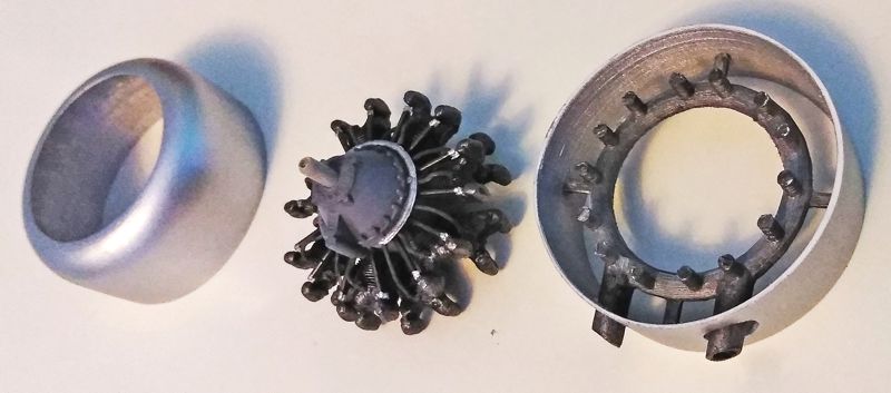
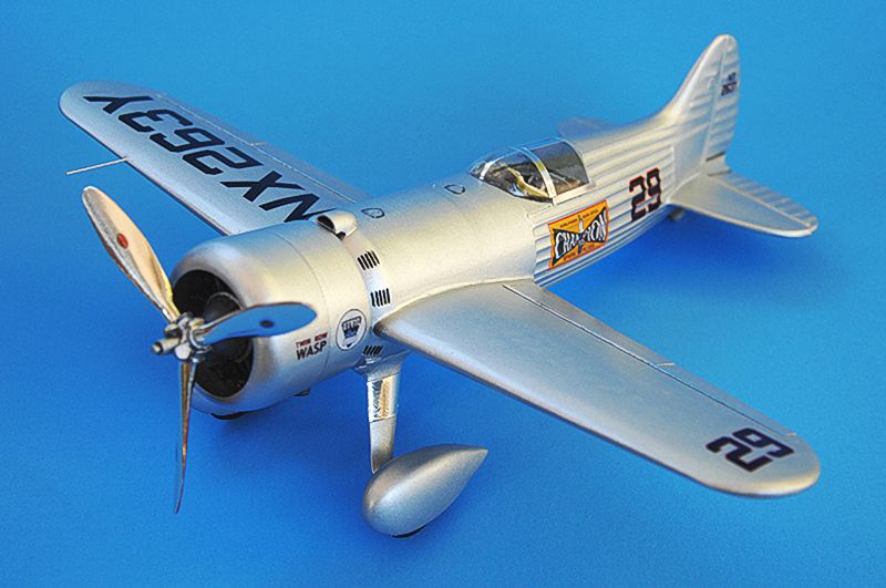
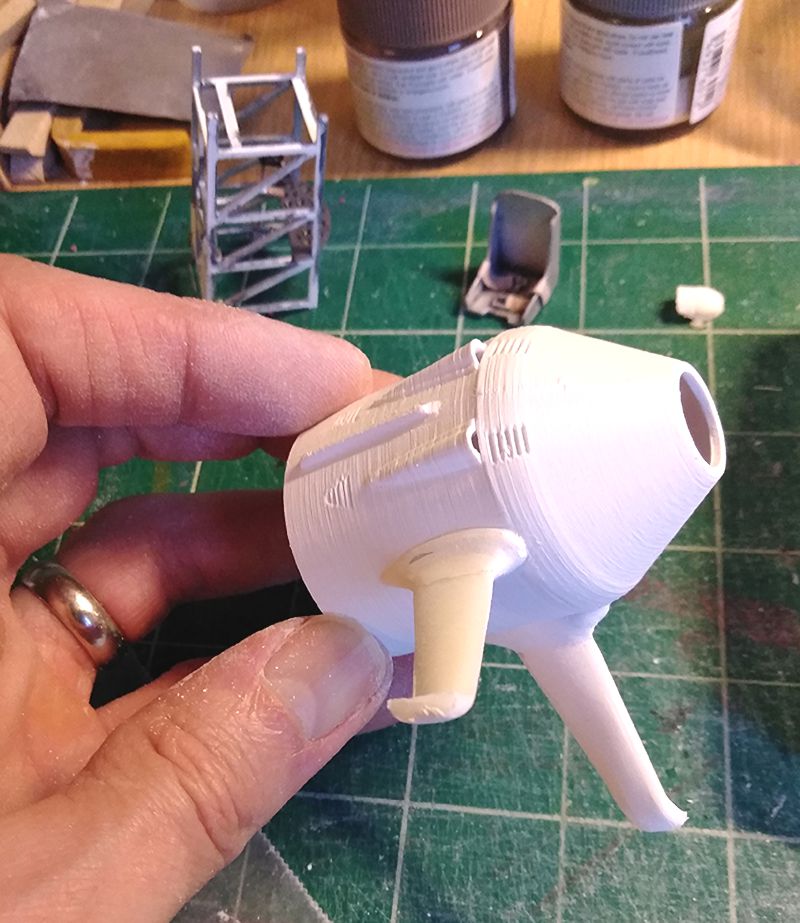
A new cowling closer to the original shape and an exhaust collector ring were designed in TinkerCad and printed. The cowling turned out really well—nice and thin, and captures the distinctive shape that bulges at the front and tapers backwards. The cowling is in 2 parts to allow me to get the engine installed. The collector ring wasn’t as successful, but will hardly be seen except for the main exhaust pipes sticking out below, so I cut and trim it as needed to fit. Its main job is to serve as a support to mount the rear cowling half. It was painted Tamiya dark metallic grey.
The engine was now completed: the crankcase was painted Tamiya medium gray, shaded with a black wash, and with the electrical distribution ring in Tamiya chrome silver. Pushrods are black with chrome tops. The cylinders were painted flat black and dry-brushed with Tamiya silver gray. All components were brush painted. I added bits of copper wire for the ignition wires. There are photos of the uncowled engine of the actual Meteor on the NASM Flickr page. It looks like this early Wasp used only a single spark plug for each cylinder, instead of the twin plugs of later versions. So only 14 wires were needed, and these were painted Tamiya German gray.
Painting and finishing
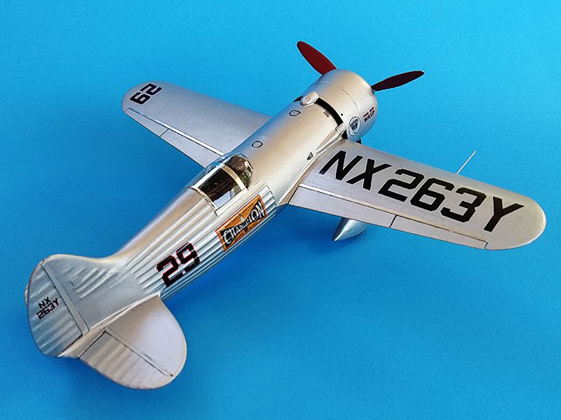
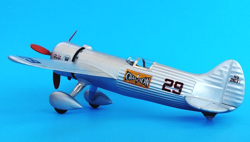
After much surface prep to get everything smooth, the model was primed with Tamiya primer, and rubbed out with fine emery paper. Then the whole thing got sprayed Tamiya chrome silver, thinned about 50/50 with Tamiya thinner, the cowlings being painted separately before installation of the engine. I used my trusty old Paasche single-action airbrush and compressor, both of which are at least 30 years old and still doing great. Several coats were needed to fix spots I had missed. The original plane was partly fabric and partly metal covered, and the entire surface was painted with aluminized dope.
I installed the engine and cowlings, with the rear cowling added first, then the engine, and finally the forward cowling to enclose it. These then got another coat of chrome silver to cover any flaws. The seam on the cowling is a bit obvious, but I didn’t want to risk messing up my previous work or knocking the cowling loose by trying to fill/sand it. I had designed the seam to fall where there is an actual break in the cowling, so at least it’s historically accurate!
Tiny air ramps of styrene sheet were constructed in front of the oil cooler scoops—these were to keep heated air from inside the cowling from being sucked into the oil coolers and reducing their performance. They are mounted on the right side of the fuselage just behind the cowling.
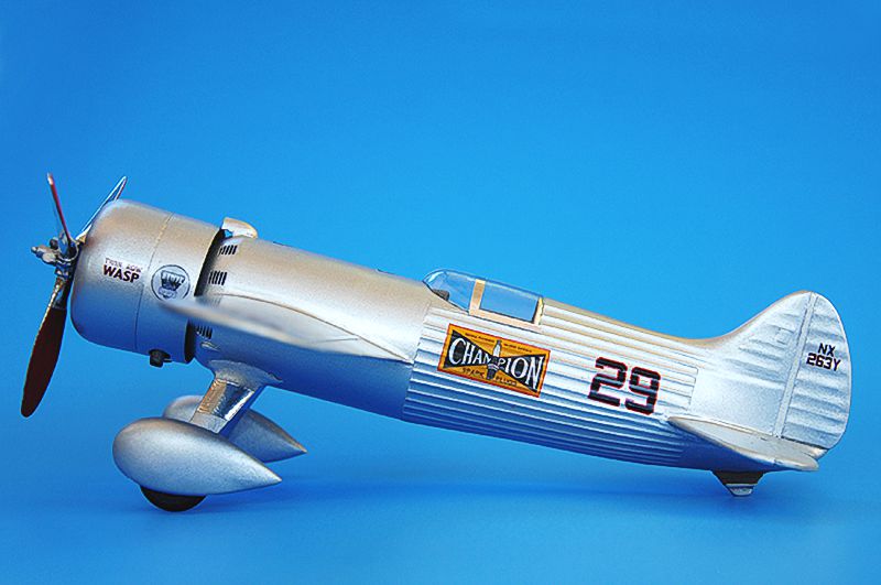
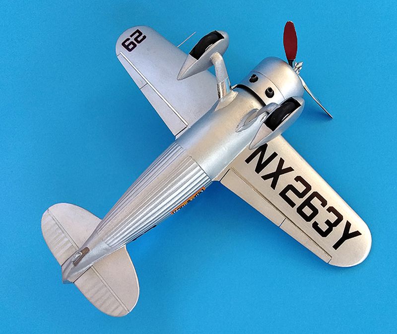
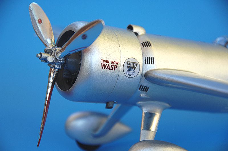
I scanned the kit decals and used Photoshop to resize ones that were too big or too small according to the Paul Matt drawings. Red pinstriping was added around the race numbers and “Champion” logo, and a new “Ethyl” logo was created from a photo of the actual plane. Research differs on which numbers and letters receive pinstriping around them. I went with my best guess as well as what I thought looked good: the “29” race numbers outlined in red, the N-numbers left plain black. “Twin Row Wasp” got red outlines, as did the tail registration number (but not the NX letters). I then printed the markings onto either clear and white-backed inkjet decal paper and sealed them with Micro-scale sealer. Meanwhile I sprayed 2 coats of Pledge floor gloss over the model, allowing a day of drying time in between coats. Thinned flat black paint was used to accentuate the cooling louvers and gas filler caps. The canvas shroud on the tailskid was painted Tamiya flat earth and dry-brushed with a lightened version of the same paint to give it some depth. I had decided not to try and create any other panel lines, I lack the skill to scribe these.
The clear-backed decals worked beautifully. However, when using Micro-Sol to help the registration number settle down, I got some white cloudiness in the Pledge finish. I had to carefully brush-paint some chrome silver mixed with Tamiya paint retarder over these areas. This disappeared under the final Pledge coat. The Champion and Ethyl logos printed on white-backed decal film proved to be more fragile. Several “tears” occurred, which prompted several “tears” of frustration to flow. However, as I was running out of summer vacation, I decided to touch up the blemishes with paint and a “00” brush rather than try and peel off the decals, print and seal new ones, etc. This turned out OK. Next time I’ll print several copies of each design for just such emergencies. After drying for a day, I hit the decals with a final light coat of Pledge and the bulk of the work was done.
With all the changes to the fuselage, the kit canopy and windshield no longer fit, and were poorly shaped anyway. I 3D-printed an approximate canopy blank and used Milliput and acrylic putty to smooth it and get it closer to the right shape. I did a lot of research online trying to find out what kind of plastic I should use to “heat and smash” the canopy. In the end, I just decided to try it with a salad container from Aldi. It’s “No.1” type recyclable plastic, and the box is big enough to get 2 good tries out of the wide, flat lid. I heated it briefly over a candle and squashed it over the canopy blank mounted on a dowel. It took a few tries but I got a decent-looking example. I had originally planned to show the cockpit in “open” position with the sides slid down into the cockpit, but the canopy turned out well enough that I decided to attach it in the closed configuration. But I left the window pieces glued into the cockpit so their painted frames somewhat suggest the channels into which the side pieces slide (you can’t see much in there anyway). The canopy was trimmed and attached with white high-tack craft glue.
I used Bare-Metal Foil to create the canopy framing. I left it shiny, though the actual framing is the same aluminum color as the fuselage. BMF was also used to create the metal sheeting attached to the gear struts to protect them from hot exhaust. I also applied BMF to a sheet of transparency film and then cut thin strips of it to apply at the aileron/flap joint. The real plane has these strips of polished metal installed to reduce drag. I glued them on with high-tack craft glue; I was afraid of what superglue might do to the paint and decals in those areas. Excess glue was easy to remove with a wet Q-tip.
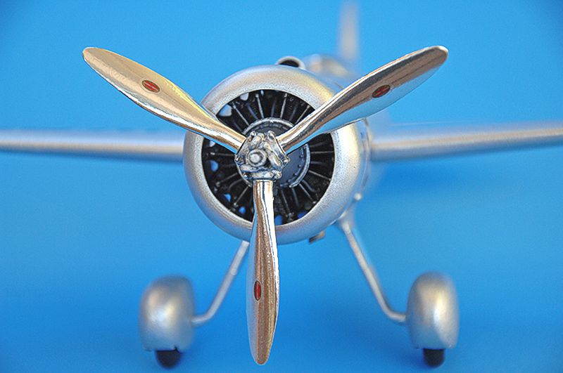
Last came the propeller. The mass balances on the hub were carved and trimmed to look more realistic, the backs of the blades were painted Tamiya flat red (some sources say they were flat black), and the hub was painted Tamiya chrome silver. The blades then got covered with BMF for maximum shine, as the real prop is highly polished. Lastly, Hamilton Standard logo decals were applied, and all of a sudden, weeks of work were done!
Conclusions
This project turned out to be much lengthier than I anticipated, but really spurred my creativity and problem-solving skills. Though not perfect, I am very pleased with the results. I think I have created something that really captures the overall shape and lines of the original. And I honed valuable skills that I am eager to put to use for other projects, including 3D printed part production and homemade decals. I encourage everyone to play around with TinkerCad (it’s a free web-based program) and soon you may be printing your own parts and accessories. There are lots of online tutorials to help you with TinkerCad’s tools, and though 3D printing seems daunting at first, stick with it and you’ll soon get the hang of it.
Photography: I used my cell phone for the process shots, and then a combination of cell phone and Nikon D2X for the finished shots. The model was posed outdoors under a shaded patio umbrella for even, indirect lighting. Lastly I posed the Meteor with a 1941 photo of Roscoe Turner from my grandfather’s scrapbook as an homage to both men. If anyone else is interested in torturing yourself—er, tackling this challenge, I will make the designs for my scratch-built pieces available on Thingiverse, where they can be downloaded for printing. Happy modeling, and as my grandfather always used to say, “fly low and slow!”
Sources
- Scalemates.com
- Oldmodelkits.com blog
- Paul Matt: Scale Airplane Drawings, Vol. 2
- Kenneth Wilson: “Something Special” article in Wings Magazine, June 1974
- National Air and Space Museum Flickr page
© Martin McClendon 2022
This article was published on Saturday, September 17 2022; Last modified on Sunday, September 18 2022