
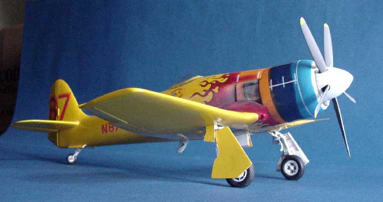
Fisher Models 1/32 Signal Sea Fury / Miss Merced 1966 -1970
By Gene Nollmann
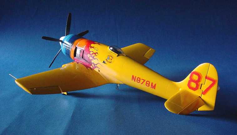
This 1:32 kit, a limited run based on Fisher´s previous kit, the Hawker Sea Fury FB.11, have all the modifications to allow the representation of the 1966-1970 Signal Sea Fury / Miss Merced race plane. Also for Fisher Model & Pattern, it was issued in their 30th anniversary year and celebrates their business 1978-2008; Congratulations!
Background
Having sold his two-place Mustang, Michael D Carroll of Long Beach, California, USA, purchased a "mothballed" surplus ex-Royal Canadian Navy Sea Fury (WG567, and civilianized as CF-VAN) in mid 1965. Carroll obtained the first US civilian registration for a Sea Fury, N878M and turned it over to Vern Barker´s Pylon Air facility (who was partnered with Don Newberger) in Long Beach for conversion to an air racer. All military equipment was removed and all the weight saved was used to increase fuel capacity to internally hold 588 gallons (vs. 240 gal. standard FB.11). The outer wing panels were clipped a total of 6.5 feet overall and the wing fold mechanisms and weapons paraphernalia removed. A pillarless panoramic canopy patterned on racing aircraft Formula 1s was added. Cockpit was updated with the latest navigational equipment.
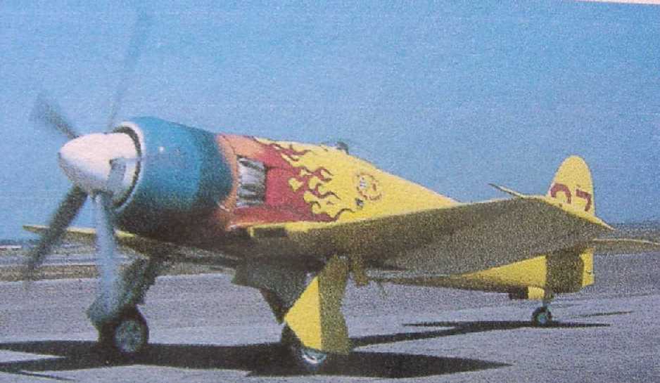
Mike Carroll´s Sea Fury emerged with a wild paint scheme that made it immediately one of the most extreme to have appeared on an Unlimited of the time and the distinction lasted for many years (the closest to "wild" was E D Weiner´s checkerboard Mustang, sometimes seen as "Bardahl II"). At the time of "Signal Sea Fury" s introduction in 1966, it was not uncommon to see various "hot rods" painted with the flame motif, but on an aircraft, it seems to have been unheard of (maybe a stigma related to being "shot down in flames"?). Today the "Signal Sea Fury" pales in comparison to the paint schemes one sees on some of the hottest racers (the latest "Rare Bear" the most recent extreme!), but therein perhaps stands the "Signal Sea Fury´s" most significant legacy to air racing history, flamboyant paint schemes.
The plane was named the "Signal Sea Fury" in promotion of the "Signal Trucking Service", a family owned Long Beach, California firm of which Mike Carroll was the president. In this case "Signal" refers to the city Signal Hill, an incorporated city within the larger city of Long Beach. On Signal Hill in 1922 a gusher oil well was struck that took four days to cap. Soon there were so many oil wells and derricks on Signal Hill that it became known as Porcupine Hill (fortunately there was no Porcupine Sea Fury). Perhaps Signal Trucking serviced the oil industry there in some way. In the early 60s the author had seen Porcupine hill (it was an astonishing sight); coming back several years later, one would never know how it had once been; it is now a densely populated area full of costly homes (and apparently no oil remains). So, back in 1966 and with race number 87, Mike Carroll was ready to go racing.
"Signal Sea Fury´s" first race appearance was in 1966 in a transcon (trans-continental race) from Clearwater, Florida to Palm Springs, California, a distance of 2038 miles. Mike Carroll finished 3rd, 40 minutes behind the winner. Considering some unnecessary blunders along the way, Mike could easily have won the race.
For their next appearance, Mike Carroll brought the "Signal Sea Fury" to Reno for the pylon races. Today the annual Reno air races are nearly a household word, but in 1966 it was only the 3rd annual holding of the event and the first time to be held at Stead Field (a then recently decommissioned Air Force Base).
The Professional Race Pilots Association had set up various pilot requirements for racing in the Reno National Championship Air Races. One of the requirements, at least a 1000 hours total time in your personal logbook or commercial pilot rating, could not be met by Mike Carroll. As good fortune would have it, Lyle Shelton, who had bundles of qualifications (commercial pilot with TWA, instructor-pilot in both Navy and Air Force, and a reserve jet pilot) and was recently hooked on air racing, was in town looking for his second "Reno ride". He had managed to "borrow" a Mustang for his first ride in Reno 65 - the second Reno race. Shelton would go on to chip away at Darryl Greenamyer´s modified Bearcat dominance of the event with his own Bearcat, the "Rare Bear".
Piloting "Signal Sea Fury" around the pylons, Lyle Shelton realized the modifications made to this Sea Fury did not help its performance around the closed course of Reno. He was impressed with its straight-away speed and quiet strength, but he would loose 40 mph in the steep banked turns, a result of the severely clipped wings (Something more power would one day cure). Shelton piloted the "Signal Sea Fury" to a 2nd place finish in the Unlimited Consolation Race averaging 353 mph; E D Weiner won at 364 mph in one of his Mustangs. Darryl Greenamyer won the overall Gold in the "Smirnoff" F8F-2 at 396 mph.
The following year Mike Carroll entered another transcon, the 1967 Palm Springs, California to Cleveland, Ohio race, a distance of 2020 miles. The "Signal Sea Fury" finished 2nd with the average speed of 386 mph, behind E D Weiner´s P-51D Mustang.
Later that year Mike Carroll entered the Harold´s Club Trophy Race, a transcon held 21 Sep 1967. Originating in Rockford, Illinois, the finish line was at Stead Field, Reno, Nevada, a distance of 1620 miles. Carroll averaged 417.346 mph (elapsed time 3:50:55) to win the race and beat E D Weiner´s P-51D by 11 minutes. Carroll had utilized the flight and planning services of meteorologist of C L Chandler, to plot a course that maximized the Sea Fury´s strengths for the predicted weather conditions. Above 25,000 feet, the P-51D of Weiner could outperform the Sea Fury all day long, but using lower altitudes and flying a course to minimize head winds, Carroll earned a very respectable win using all the piloting skills and disciplines he had acquired. Mike Carroll and the Centaurus powered Sea Fury gathered a unique distinction, the only air-cooled radial powered aircraft to win a post World War II transcon race (how long will that stand?).
The rest of ´67 and early ´68 were spent reconditioning the former "Cobra II", a P-39Q Airacobra modified for pylon racing back in 1946. Having much success as a pylon racer at the Cleveland National Championship Air Races, "Cobra II" won the Thompson Trophy in ´46.
The plane, now renamed "Cobra III", was thought ready for testing. Having completed a few hot taxi runs and low lift-offs and landings on the long runway of Long Beach airport "Cobra III" was deemed ready for a test flight. On 10 Aug 1968, Mike Carroll piloted "Cobra III´s" maiden flight out of Long Beach airport heading low and straight to the coast. FAA restricted him from maneuvers until away from populated areas. As Carroll neared the coast and appeared to attempt a slow right turn, the aircraft went out of control. Carroll´s friend, E D Weiner, flying chase, witnessed the events from a distance. Mike Carroll bailed out the Cobra´s auto-style side door and hit the horizontal stabilizer. He was not able to open his shoot and fell to his death. The "Cobra III" crashed into a coastal Naval base without injury to ground personnel.
The "Signal Sea Fury" was sold out of the Mike Carroll estate in 1969 to Dr. Sherman Cooper whose practice was in Merced, California. Renaming the plane "Miss Merced", Cooper managed to race the plane with some relative success in Reno and did even better on longer races.
In November 1971 with Cooper piloting, "Miss Merced" suffered an engine seizure (Some attribute this to over-taxing the engine in the recent Reno pylon race in which it placed well). Cooper was able to make a dead stick landing that broke-off the landing gear, cracked the planes back and severely crunched an outer wing, but he managed to walk away. Fate would not be satisfied. A few months later, while flying his Pitts Special through acrobatic maneuvers, he suffered a fatal accident when the right lower and total upper wing separated.
"Miss Merced" remained dormant for a time but then was picked up by Frank Sanders and then passed along to Jim Mott. He had her put back into flying condition close to standard configuration. She was now fitted with a full wing and conventional canopy and renamed "Super Chief" (first flight in 1988).
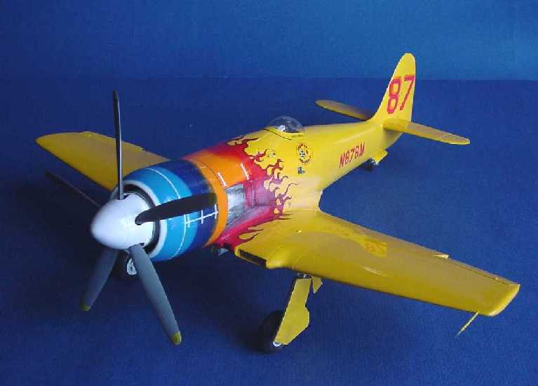
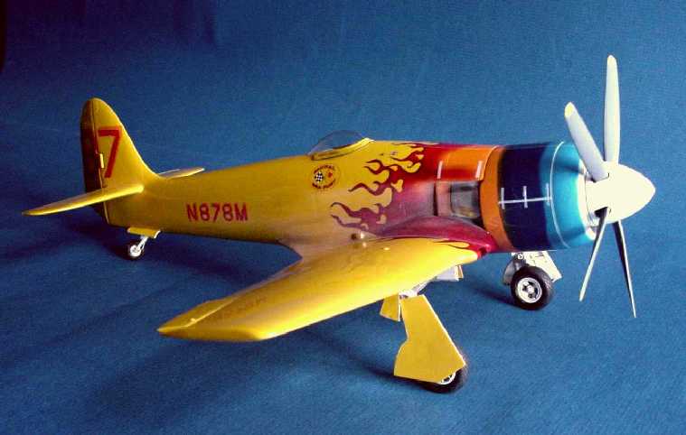
The plane was sold to Steve Boulanger & Jim Michaels. They had the Centaurus removed and installed a Wright R-3350. The "Miss Merced" name was revived and sported again the white-hot spinner replaced by yellow, cool blue cowl, and a gush of flames all the way past the canopy and once again bore race number 87. She was in the air again in 2000 and became quite competitive.
Mike Carroll´s highly modified wing found its way to another Sea Fury. Some time ago, it was observed that the Carroll clipped wing needed more power to become effective. Perhaps point was proven - it is the wing coupled with a higher output engine on "September Fury"!
Throughout N878M´s race career covered by this Fisher kit, the overall graphics remained in the same general layout, but detail difference did crop up specific to various times and places. Fisher´s kit provides what you need to model any of these variations from 1966 to 1970.
The later iteration of the "Miss Merced" theme with a full wing, full canopy and very similar but distinctly different graphics, is not intended to be modeled from this kit.
Features of the Kit
As near as the author can determine by comparison to available photographs available in the references listed below, Fisher´s kit incorporates all the visible changes of the FB.11 that would be required to represent the "Signal Sea Fury / Miss Merced" 1966 - 1970. This would include the clipped wing (with a lack of wing fold mechanism), partial closing of the cockpit deck aft of the seat, a small racing style pillarless bubble canopy, removal of the tail hook and attachment fairing, and re-profiling the bottom of the rudder. There are cockpit differences as evidenced by a new PE fret unique to this kit. Having no access to a cockpit photo, the modeler is guided amply by the instructions.
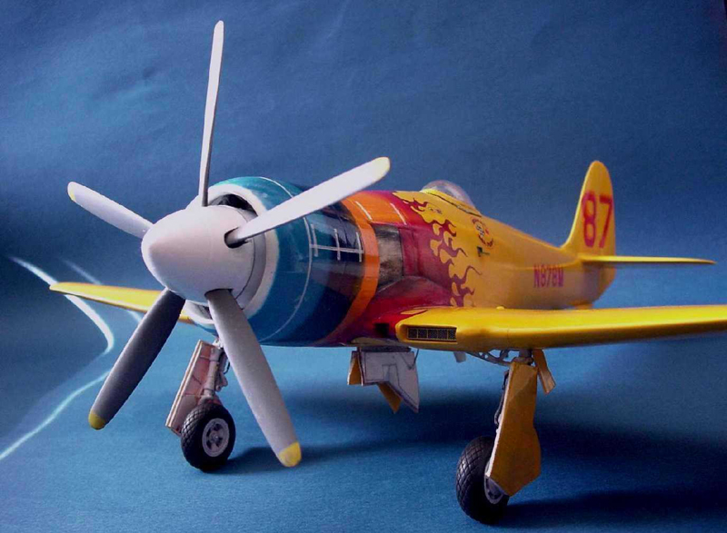
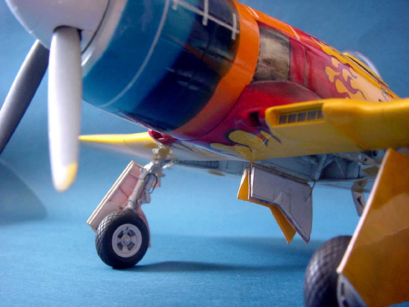
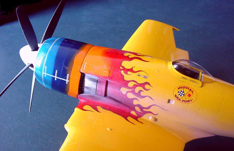
The most obvious feature of the "Signal Sea Fury / Miss Merced" are the "hot rod" style flame graphics reminiscent of action hero comics or circus posters depicting a lion jumping through a ring of fire. For this feature the kit thankfully provides decals developed and printed by Zotz Decals under Eli Raphael.
For those familiar with Fisher´s issue of the FB.11, gone are the 3-piece wing, being replaced by a one-piece wing with all the basic wheel-well detail molded-in. Some minuscule resin pieces help detail the open wheel wells. Resin flash clean up is minimal for a kit of this type. Instructions caution to wash all the resin parts with household bleach. The author did this and added a little amount of dishwasher soap. No evidence of "fish eye" occurred during the painting process.
Procedure of Construction
Traditionally kits will start you off with the cockpit, but there are also other areas needing construction before closing up the fuselage. Fisher starts off with a simple but quite elegant sub assembly that will create some confidence in the kit and allow the modeler to get acquainted with Fisher´s resin.Prop & Spinner (Step 1)
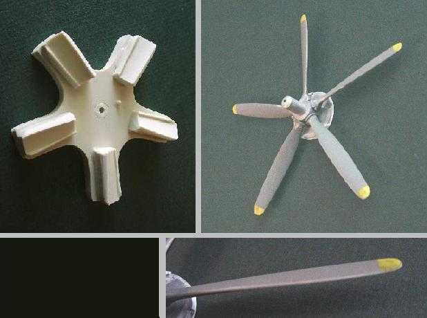
Kits by modelers for modelers are fun and in this case is evidenced by Fisher´s care in setting up the prop. The agony over prop blade spacing and angle can take a toll, so the author was impressed with the "prop blade to hub jig" provided in the kit. It simplifies life sooooo much. Too bad this wasn´t a 4 or especially 3-bladed counter-clockwise prop - the jig would be a handy tool for other models!
One thing the author found helpful in using the jig was to sand away a portion of the leading edge support so that the blade can lay snugly onto the jig and just catch the trailing edge support. For the author, the leading edge support curved around and prevented a uniform angle for all the blades.
When done, blade spacing will be correct and blade pitch will be the same for each blade. A real confidence builder!
Fisher´s instructions also will give occasional finish descriptions, which the author especially appreciates, not having a lot of photographic reference to work with. The fronts of the prop blades are described as having a "faded" appearance overall even on the yellow tips. This was attempted by giving the blades a coat of buffing aluminum Metalizer, sealing, and overpainting with the colors recommended. With a soft cloth, the blades were burnished until some of the aluminum undercoat would blush through, especially on the leading edges. With that accomplished, they were given an overall clear Dullcote. The result is subtle but effective, but one of those things too subtle to photograph well.
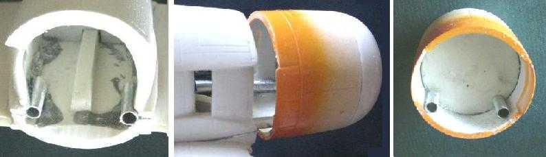
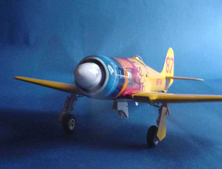
Engine & Cowl (Step 2)
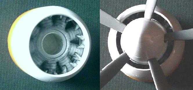
The kit provides a representation of the amazing Centaurus sleeve-valve engine (fascinating concept and a tremendous credit to the perseverance of Bristol engineers to make it work well). Unfortunately in racing form it seems to defy higher-output tweaks. The Fisher kit provides representation of the front nine cylinders and the front face of the back nine cylinders. For what can be seen between the huge spinner the interior cowl fairing, the kit provides more than enough to satisfy any modeling judge´s examination even with a snorkel probe and penlight!
The resin cluster of nine exhaust pipes attaches to each side of the cowl and can be painted and installed at the last minute - with all the specialized finishes in this area, this was very useful.
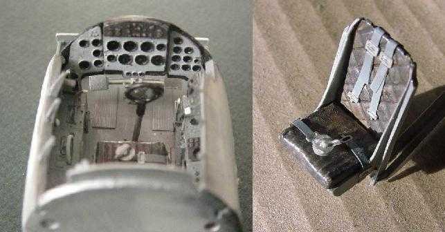
Cockpit (Step 3)
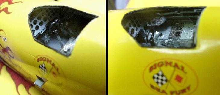
The cockpit owes its heritage to the very fine cockpit developed by Roy Sutherland for Fisher´s FB.11. The restricted view through the small cockpit opening of the FB.11 is even smaller in the "Signal Sea Fury", but the cockpit kit is a gem and a delight to build. Mr. Fisher could just as easily supplied only a seat and called it adequate (and it would be); it is to his credit to give the modeler this special treat. As it is, the civilianized cockpit uses much lighter colors and allows for better viewing.
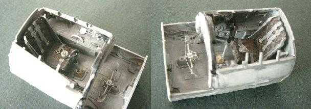
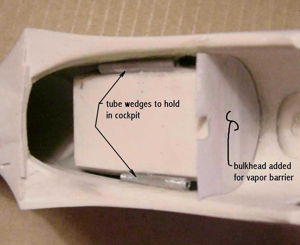
The completed cockpit package fits snugly into the fuselage, but exactly how to secure it in its place required some thought. On top of the wing center there is a raised bar that just about supports the cockpit, but doesn´t quite reach. The author fastened some large aluminum tubes to either side of the gap between the cockpit tub and fuselage, thereby "wedging" the cockpit in place. A full fuselage barrier of heavy card was also added to stop paint fume/dust from migrating into the cockpit area during the painting process.
Wing / Fuselage / Cowl (Step 4)
Every kit has it strengths and weaknesses; a bit of a somber beginning for which the author apologizes. Models are made for Modelers to build and it is the challenge and the pursuit of high standards that are its rewards - actual conquest (completion) is somewhat less significant, but also desirable. Just a personal thing, the author has always enjoyed the building process much more than viewing the finished model and except for this venue (LSP), rarely shows the finished model to anyone (nearest model club is half-a-day´s drive away).
On this kit the challenge is unquestionably the intersection of the "wing / fuselage / cowl" - it contains difficult and complex surfaces to mate and blend, 6 "fuzzy" color transitions, and 60% of the total decal surface of the model. If you want this fascinating bird in your collection, be prepared with loads of patience and careful timing while working in a limited space.
Even with a manufacturer as professional and thorough as Fisher Model & Pattern, there are extenuating reasons for fit problems. Apparently "resin" as used in the models we are familiar with, never really finishes curing. Certain chemicals continue to escape from the time they are cast into the motion of "curing". Of course the greatest percentage of volatiles escape very early in the "curing" of the cast pieces. The process continues for a long time, but the amount of outgasing tapers off and in the end would be very difficult to measure (kind-of a half-life decay process). The point being however, this "escape" of material results in some dimensional degradation, i.e. "shrinkage" and/or distortion. The changes seem to be unpredictable, perhaps depending more on the local density of resin (thick or thin area), original mix, etc. Things that once were a snap-fit will evolve to requiring some work to come to a proper fit. A long story, but this kit was a couple of years down the road from date of casting before it was built and some minor fit problems appeared in the "wing / fuselage / cowl" area.
The instructions mention the fuselage to wing connection as a possible problem and suggest the work necessary to achieve the proper fit. Related to that connection is the end profile of the cowl (basically a circle) and its fit to the main body. Somewhat aggravating this is the peculiar transition in this area on the actual aircraft - a solution by Hawker that dates back to the transition from Napier Sabre power to the Centaurus powered Fury (refer to airframe LA610). The odd transition is mostly noticeable in profile where there is a distinct "kink" in the top of cowl transition. Therein is the modeler´s challenge; make the surfaces meet but don't loose the subtle "kink".
The author found it most convenient (been watching too many Charlie Chan movies) to devise a pin & tube arrangement to facilitate frequent placement & removal of the cowl (the cast-in lugs were removed since they interfered with this process). In this way each area could be worked to meet and align without filling-in &/or sanding away the "kink". (The author was really hoping to apply the gloss paint to the wing and fuselage separately, but this proved to be not possible. It would have been much easier in that way to balance the orange peel / run / gloss problem, but with Tamiya´s rattle-can gloss it turned out to not be much of a problem).
Canopy (Step 5)
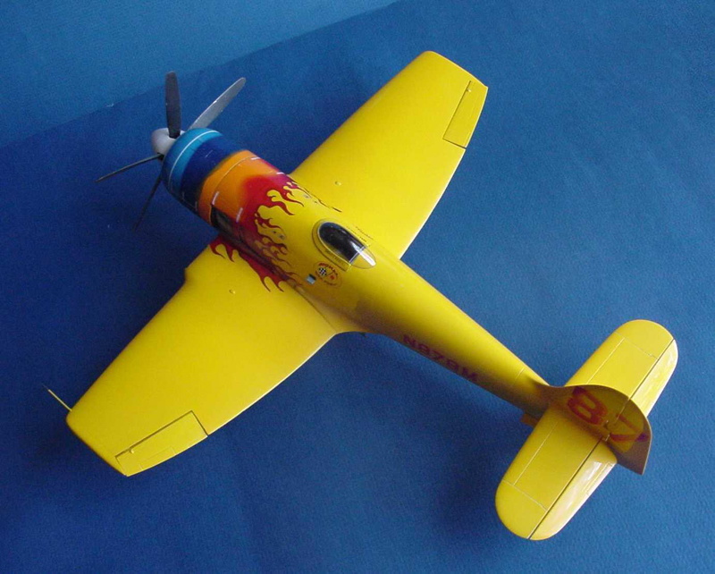
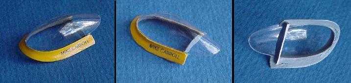
The pillarless panoramic canopy is vacu-formed. Two are provided in the kit and a resin pattern if you should want (or need?) to fabricate another. The trim and fit are quite forgiving, with the exception of how the loose trailing end of the canopy framelessly lays on the fuselage deck (as the actual aircraft).
The trimmed canopy was attached to the painted frame using white glue. The "Mike Carroll" decal was applied and the whole assembly was dipped in "Future" (being careful not to float the decals off).
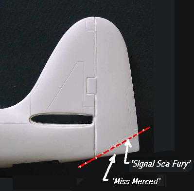
Tail (Step 6)
Fisher has removed the tailhook attachment housing and re-profiled the rudder as the "Miss Merced" version; the modeler will need to cut away a piece of the rudder for the earlier versions of the "Signal Sea Fury". The rudder is molded into the vertical tail and will need to be cut away to represent the slight kick as seen in most static photos of this plane.
The horizontal tail will require some careful shaping at the fairing joint with some minor gap filling and sanding. The basics are there and all will come out nicely. The elevators are separate pieces and require a little work to fit properly.
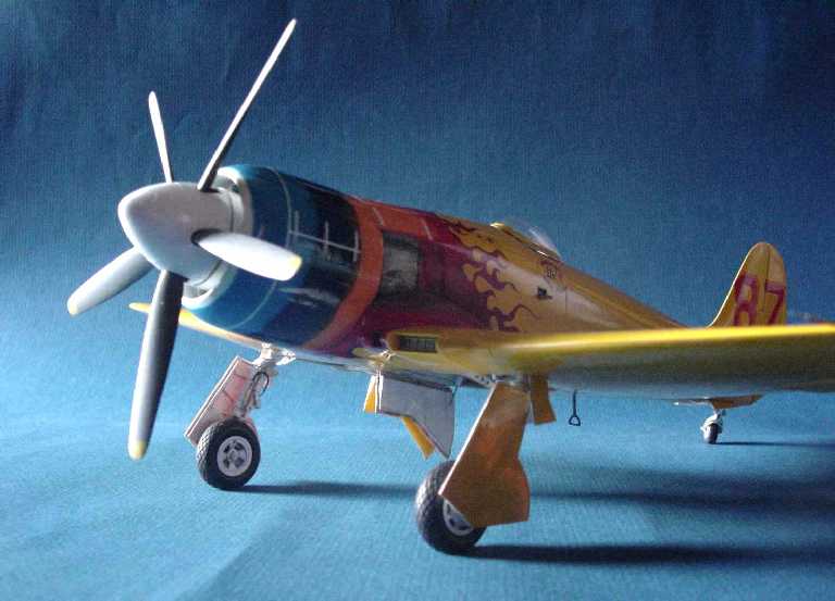
Landing Gear (Step 7)
The landing gear is supplied in brass castings and requires some parting-line clean up. They are robust and quite able to support the weight of the finished model. Mounting is by a large end lug and a corresponding lughole cast into the wing. Care must be taken to get the leg angle correct and the same angle in each leg.
Resin tie-down lugs are provided to add to the gear. The addition of a hydraulic line (or is it an airline?) will complete the dress out of the gear. Much of the gear leg and wheel detail is hidden behind a large gear door, which fortunately is also nicely detailed.
The wheels and tires are separate pieces to facilitate painting. The tires come flatten, but there was no valve stem coming out of the wheel in which to pump up the tires. Hopefully they will still roll with a full fuel load.
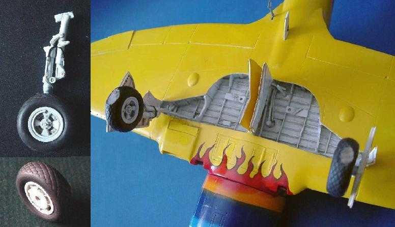
The kit provides resin retraction arms, springs and retraction rams to round out the wheel well - to - landing gear image. Small diameter precision stainless steel tubes (hypo type) were substituted in the retraction rams to represent stainless steel ram shafts.
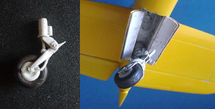
The tail wheel carriage is an amazingly complex single casting. The tail wheel fit was a bit loose so the author drilled the carriage and the wheel to receive a small diameter brass pin axle. Worked like a charm.
Bits & Pieces (Step 8)
Apparently while sitting on the field waiting for a pilot, a little step just below the port side of the canopy remains open and a step stirrup hangs below the trailing edge of the wing. The kit provides for both in resin.
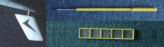
External evidence of the updated navigational avionics is the ventral Loran antenna complete with logo (Supplied as a decal).
The resin Pitot tube was replaced with some telescoping diameter precision stainless steel tubes. A guide hole is cast into the wing for placement.
Also part of the PE fret are a couple of pieces that makeup the wing oil intercooler intake screen and frame - a nice bit of detail.
Painting (Step 9)
The cockpit followed the Fisher instructions using Model Masters 1740 - Dark Gull Gray FS 36231 for the basic interior color and Model Masters 1735 - Light Gray FS 36495 for the instrument panel pieces. The Dark Gull Gray was also used for the underside of the canopy.
The instrument film backside was overpainted with silver, hoping more reflectance would occur - white would have been satisfactory. Each instrument film cluster was applied using a coat of "Future Clear Acrylic" and laying the PE panels onto the wetted film. When dried each instrument had a nice clear lens and an effective bond of film to PE (in time this may delaminate, but then, so will several other things as well).
The seat was given a coat of Model Masters 1735 - Wood, a nice medium tan color, then sealed with "Future Clear Acrylic". Theory being the acrylic would be a dissimilar barrier between the tan underpaint and the topcoat. When dry, a topcoat of flat black was applied, it was "buffed" with a Q-tip to polish like worn black leather; the black rubbed away in the hi-contact areas to reveal leather worn below the dye surface.
For the exterior it was decided to stick with a Tamiya paint system all the way through. The Fisher kit recommends Tamiya 87044 - Fine Surface Primer (L) (White) in a rattle can. Thanks for the introduction Paul, this is a really great product! Over that primer, Fisher kit recommends Tamiya TS-47 - Chrome Yellow in a rattle can. Tamiya gloss paints are a true hit or miss befuddlement and the author truly balked at using their gloss in a rattle can, but mystery of mysteries, their rattle can gloss flows like one would expect a gloss to flow and with sensible care runs can be avoided and still get a good gloss (one good tip by Paul, ". . the yellow will usually flow out and look like glass in a day´s time."). Also, if there are multiple coats anticipated, it is very important to let each coat dry thoroughly (at least a day, preferable more). One caution, if you think it is dry and ready to handle after 2 days - wait another 2 days; firm finger pressure for any reason can leave an impression if not thoroughly dried (this is something the author should know, but constantly forgets, much to his chagrin). There is enough paint in one rattle can (100ml net vol.) to give two full coats of paint and leave good pigment density (however, color of the underpainting is a significant factor).
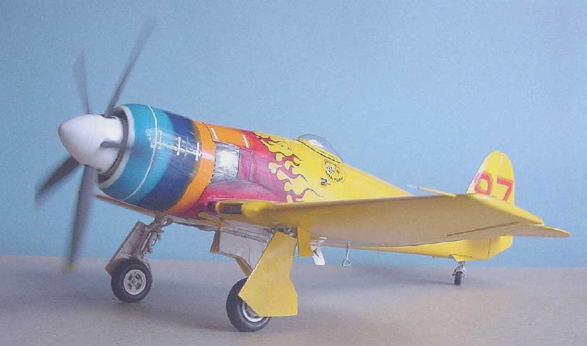
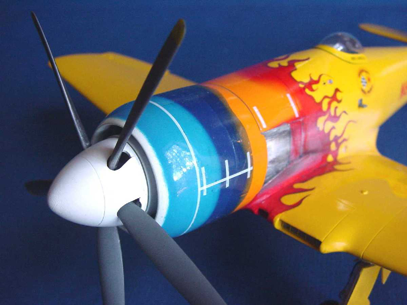
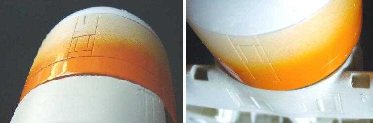
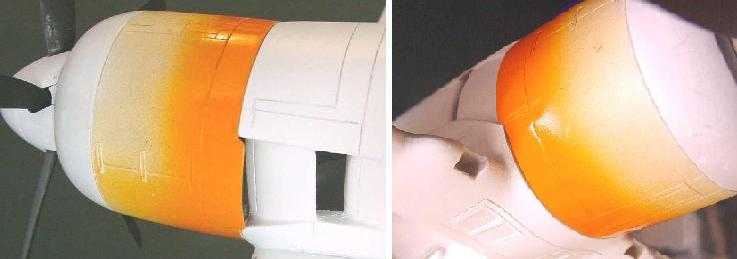
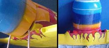
On the cowl, first blush was Tamiya acrylic - X-02 White, followed by Tamiya acrylic - X-06 Orange (a deviation from kit recommendation) and then the light blue, Tamiya acrylic - X-14 Sky Blue (a deviation from kit recommendation). Last was an application of the darker blue, Tamiya acrylic - X-04 Blue. The same Orange bridges the cowl and main body.
An overall coat of Tamiya acrylic - X-22 Clear [gloss] was given the plane, lightly sanded when thoroughly dry, and then coated a second time. The biggest concern was to build a protective cover for the flame decal (See below and "Final Finishes" that follows).
Markings
Block Letters & Numbers (Step 10)
The decals include the race number "87" in a Red-Orange with a drop-shadow in Yellow. Unfortunately, the drop-shadow Yellow looks awfully close to matching Tamiya´s TS-47 Chrome Yellow used for the main body and most likely would hardly be noticeable. A review of the black & white photos reveals a definite contrast between the main body Yellow and the number´s drop shadow; further, the drop-shadow seems to be very close to the Orange area of the cowl. Interpretation of black & white photos is wrought with pitfalls and difficulties (film used, filters used, exposure, qualities of the sky/lighting, and location in the world). Basically the author is clueless to tell what color is what on the gray scale, but in this situation, when two grays closely resemble each other and one is known by color, the author felt confident in using the same or similar color for the unknown gray. Okay, that´s a target on the author´s back, but something needed to be done for that drop-shadow of the number. Now, how to get that.
Fortunately the items affected were made of numbers and letters all having straight lines. Curves could be handled in this way also, but requires another magnitude of patience. Even the "8´s" were typical block letters made up of straight lines.
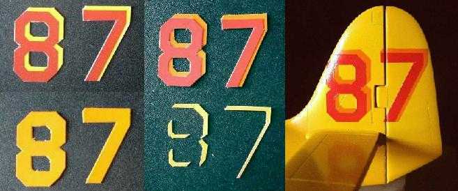
A piece of clear decal paper was sprayed with the Orange color used on the cowl. Care needs to be taken to build up in light coats so as not to set off the separation of the clear decal carrier (because of using water-based acrylics on decal film). When it was thoroughly dried, the now painted sheet was over-sprayed with a clear lacquer decal bonder (also light coats). This helps in the decal handling/application and gives a good smooth glossy bridge over the mist coats that tended to be a bit rough.
Next the kit-supplied decal was secured with tape at its edges over the solid Orange color sheet, being careful to avoid the printed image. All the numbers and letters were cut out on the outside edges of the complete image (i.e. Red number and Yellow drop-shadow together). With a complete Orange background, the Yellow was trimmed away and the Red number retained. (All this was a great time-eating diversion enforcing the discipline of allowing paint coats to dry properly!)
Next, the Orange letter/number was applied to the model and when thoroughly dried, sealed with Tamiya acrylic - X-22 Clear [gloss]. The trimmed Red letter/number was then applied over the thoroughly dried clear coat. This was necessary to allow time to correctly position the Red element. Once thoroughly dry, the decals were given a second coat of clear.
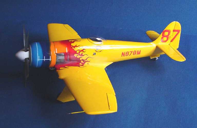
The decal sheet provides four sets of the large "87´s"; two are used on either side of the vertical tail. Presumably the other two are for the wing, but the author could find no application of numbers on the wings in the photos available to him of the "Signal Sea Fury". The wing numbers would make sense for a pylon racer where they are usually in a steep banking turn, but for cross-country racing they are not of much use. The "Signal Sea Fury" appeared in only one pylon race, Reno ´66 (did it have wing numbers?). Perhaps sometime in N878M´s life as "Miss Merced" it had wing numbers. Without specific information, it was decided to not apply wing numbers (if that is what they are).
The Flame Decals (Step 11)
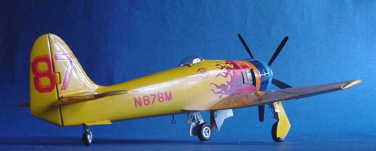
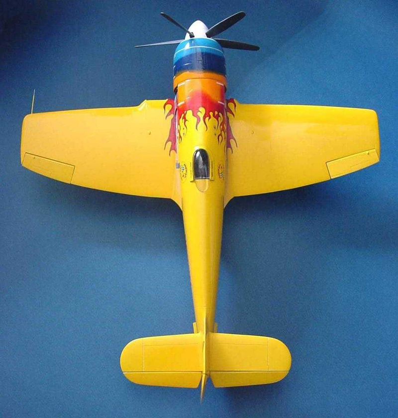
In studying the "flame" decal and the instructions, the author noticed that the leading edge (closest to the nose) of the decal is done with a gradation (from faint to dense red color). In a departure from the instructions, the author reasoned that if the Orange were "underpainted" and the decal laid on top, a gradual gradation of Orange to Red in the flame could be achieved more effectively than if the author tried to airbrush the transition. The intricacies of the trailing edges of the flames also challenged the author´s ability with the airbrush to avoid unwanted Orange overspray onto the Yellow main body of the aircraft. Recovery from such an event is difficult to imagine.
The notion of underpainting solves one problem, but it still remained to also not extend the underpainting beyond the field of the flame. The solution was to lay the decal under an artist´s low-tack Frisket film and trace the flame pattern and then determine how far back under the flame decal should the painted Orange field be extended (green line in pic). With the Frisket trimmed the resulting paint mask was applied to the fuselage, anything not requiring Orange was covered and the Orange was painted.
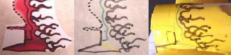
Unexpectedly, when the Frisket was lifted off the decal, a thin pale yellow film was also lifted off some areas of the decal. Frisket is a low-tack masking material commonly used by artists wishing to separate areas on paper and canvas; the damage to the decal was both a big surprise and disappointment. A small test determined that the remaining "lifted" yellowish film still on the decal would not disappear when overcoated, so the rest of the "lifted" yellowish film that did not separate had to be painstakingly removed. When done this was given a couple coats of Microscale Liquid Decal Film (this product has saved the author"s day on many occasions, especially with old decals).
After the cowl Orange thoroughly dried, the Red decal was applied over it. One goal in printing decals is to make them as thin as possible to give that "painted-on" look. The trade-off is the potential of a carrier film too thin to standup to handling. Considering that the flame wraps from wing root to wing root over the cowl, an unusual amount of handling can be expected. The thinness coupled with the author's "Frisket abuse" had consequences. And sure enough, the decal did break up in places as it was being positioned. That required some careful touch-up, but the good news was that the Orange to Red transition worked out beautifully. (And wouldn't it have been wonderful if the Dark Blue band had been supplied as a decal).
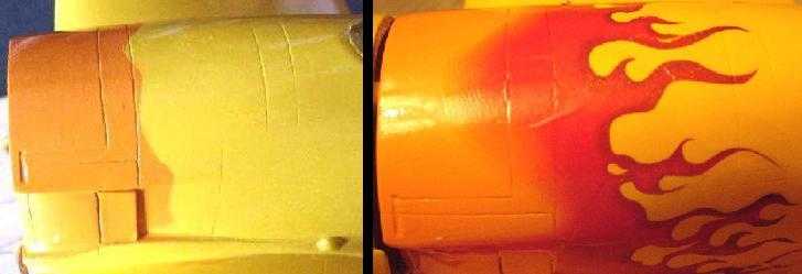
The "un-abused" ventral flame and wing-root flame laid down fine without problems. "Fuzzy" pieces (gradation pieces) of the other flame decal (which were intended for the alternate paint scheme) were used to devise a transition area on the bottom of the cowl. This could not be applied directly in one piece but required numerous cut & fit passes. This may not correspond to "reality", but an abrupt Orange to Red line did not seem appropriate.
A light coat of Tamiya acrylic - X-22 Clear [gloss] was used to give a protective coat to the decals and create a barrier for touch-up applications. This technique was quickly learned when touching up a small spot with Red only to see it migrate under the decal all the way to the other side and shout back from under the clear carrier film! Recovery from most errors in paint can be very discouraging and usually require the investment of a lot of time. But with the flame decal, a sense of "do-or-die" seems to hang over the process. Tying-in of the "flame" decal was done with Tamiya acrylic - X-07 Red and Tamiya acrylic - X-18 Black.
The exhaust shields were done with Bare-Metal foil; the edges were lightly touched with some "Future" to discourage lifting. The material of the foil is aluminum, but the actual shields were most likely stainless steel. Some "Gunmetal" Model Master Metalizer was used to "knock" down the shine of the plate and to shift the hue of metal from the coolness of aluminum to the relative warmth of stainless steel.
Final Finishes - (Step 12 - there had to be 12 steps!)
Scale Gloss?
An interesting esoteric modeling subject circulates occasionally, that is the notion of "scale color". It is at first baffling, but can make some sense in that whatever scale you model, the finish subject is "as viewed from a distance" (even though you might only be inches away). In considering scale, there is some air density between you and the observed plane (this also affects any photographic record of the same subject). That air density has some accumulated affect, the same as a filter, and will vary with the distance of the sample and the fine "dust" particles floating in the air (a nice baseline would be to view the same subject in the vacuum of space). Depending on where, when, and how far, all this will affect the "apparent" color and hence the "scale color".
Similarly with the "gloss" of a plane, all those influences affecting "scale color" also affect "gloss" but with an added influence - the depth of the gloss. Gloss is the result of a clear carrier paint rising to the surface and having a shiny appearance when dry (this also helps "seal" the paint and drastically retards oxidation). Show cars might even be finished off with several pure "gloss clear coats" to enhance the "depth" of the finish - giving an illusion similar to looking into an ever wet pond. Generally racing aircraft are "shiny" because they have been polished and waxed to be slipperier in the air (less drag). Questionable would be the assumption of layers of clear coat on a race plane - that´s just dead weight and doesn´t improve racing performance (although it does thwart oxidation of the paint and oxidized paint will add drag).
So, question is, is there a "scale gloss"? It would take a sensitive micrometer to measure, but the physical depth of gloss has a dimension and 1:32 of that would be very small indeed. The real danger is applying to your scale model a gloss that is quite similar in dimension to a full size gloss coat and consequently actually throwing the model "out of scale". After all, what is the difference in depth between your model´s gloss coat and that on the full size aircraft (Same paint, same depth, hence, not to scale)? A casual viewer is sensitive to this and will occasionally see a model with a wonderful thick gloss finish, but somewhere in mind (and seldom expressed) is also a sensitivity that the subject is no longer a "scale miniature" but is simply a "model" verging on "toy". That is when a simple gloss coat has become too heavy. Yes, "scale gloss"' is something to consider and difficult to manage.
For this model as mentioned before, two coats of Tamiya Clear Acrylic were applied to the main body (because of protection needed for the two layers of decals used for the numbers) and one coat for the cowl.
All this was first wet sanded with 1200 wet/dry paper. All the significant irregularities were removed at this stage (Such as, the occasional dust particle, some overspray dust, minor runs, etc.). This was followed with the use of the Micro-Mesh 6-step abrasive polishing pads. The use of their Micro-Gloss helped tie all the polished areas together (for example, the port fuselage was done and then the starboard fuselage was done; the transition at the top of the fuselage was a bit "fuzzy" and the Micro-Gloss rub helped tie it all together). If you have never used this system, treat yourself on your next "shiny" model; it is terrific and as close to magic as can sensibly be expected. Net result, a finish that was not overly heavy in "gloss depth", but slick enough as to not rob precious horsepower on a long transcon. But the author does realize that the "true" scale depth in gloss was not achieved, in large part due to having to protect the decals with the use of gloss coats.
Smoke & Oil & Speed Tape
Tamiya makes a Flat Base (X-21) which was sprayed in the general area of where engine exhaust would accumulate along the fuselage. This became the "course" base or "tooth" to receive and hold the pastel powders selected to represent some of the various light grays, tans, and charcoal grays that seem to be in evidence in some photos likely taken just after racing or a long cross-country trip. The flame decal seems to have some of that worked into the decal, which makes matching a bit problematic. The Flat Base was taken straight from the bottle and thinned a bit with Tamiya thinner. When dry, areas that did not require the "flattening" treatment could be polished out.
Judging from the sculptural detail following the exhaust ports of the actual aircraft, it would appear that the Hawker aerodynamicists were anticipating a different airflow than what actually occurred behind the prop-wash. Instead of flowing within a sculpted channel, the exhaust trail follows its own dictates somewhat parallel to the top-of-wing while freely spilling out of its channel sides.
One photo showed some interesting oil streaks on the face of a landing gear cover; the streaking would have lined-up perfectly with the exhaust end of the internally mounted wing oil cooler. This was also done with some black pastel mixed in with dishwasher detergent and brush applied.
Some photos show white lines over some cowl joints; the author presumes they were tape applied in the interest of blocking air leaks that could interrupt the initial airflow over the cowl and hence induce some drag turbulence along the fuselage. With a couple thousand horsepower and speeds in the high 380s, one wonders how effective this is, but it does add some interest to the "look" of the plane, so it was added with white decal film.
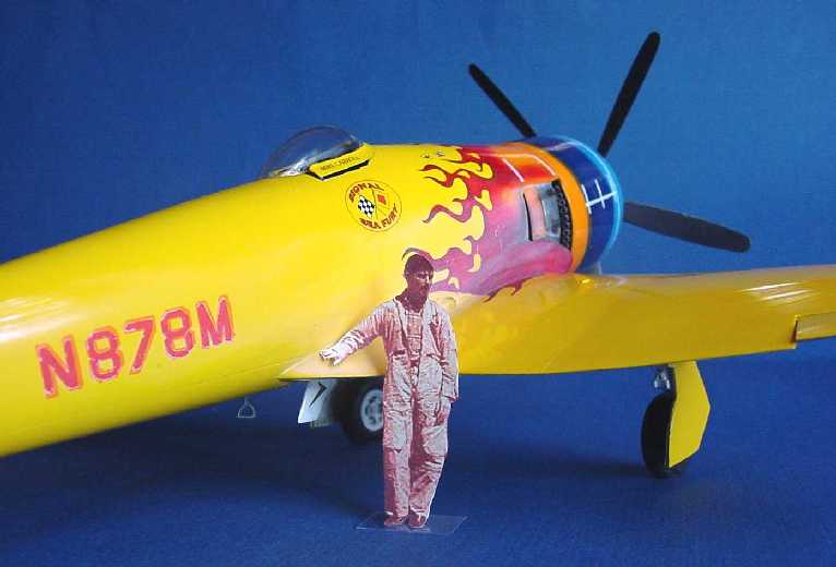
The "actor" posing as Tom Cruise in "Top Gun" is actually a pic from Fisher´s instructions of Mike Carroll shortly after his surprise win of the 1967 Harold´s Club Trophy Race; it is just a paper cutout adjusted to approximate scale and printed with a "tan" cast to the overall pic.
Conclusion
With 120 hours in his personal pilot´s logbook and 6 hours of dual instruction in a P-51, a 30-something Mike Carroll began flying a newly purchased Mustang. A year later the P-51 was sold and Mike Carroll bought and modified a Sea Fury and raced it cross-country averaging 325 mph over a distance of 2038 miles. Two years later he would die taking another performance aircraft on its maiden flight.
Aircraft are complex mechanical systems; it took a lot of test pilots with temperaments similar to Mike Carroll´s fearless pursuit of performance to bring aviation to the level of safety we experience today.
The "Signal Sea Fury", with all its race-plane features and dashing flamboyant paint job, sits on this authors shelf as a reminder of a distant, remote & private activity that had immediacy and consequences that lifted us up on their shoulders for a closer peek of the heavens.
If your airbrush and painting skills are of a high calibre, this model will challenge and reward your efforts. The author falls far short of those criteria, but in the end, still had a good time. Thank you Paul Fisher and company for making available this piece of history to grace our collections and have a fun and enjoyable diversion in the process!
Materials Used
Glues
- Zap-a-Gap PT-04 - Medium CA+ [cyanoacrylate]
- J-B Weld - Epoxy Steel [2-part slow curing]
- Elmer's Glue-All - Multi-Purpose Glue a.k.a. white glue [not a chemical bond, but can be surprisingly strong in certain situations]
Paints
- Tamiya 87044 - Fine Surface Primer (L) (White) [rattle can]
- Tamiya TS-47 - Chrome Yellow [rattle can]
- Tamiya acrylic - X-02 White
- Tamiya acrylic - X-14 Sky Blue (deviation from kit recommendation)
- Tamiya acrylic - X-04 Blue
- Tamiya acrylic - X-06 Orange (deviation from kit recommendation)
- Tamiya acrylic - X-07 Red
- Tamiya acrylic - X-18 Black
- Tamiya acrylic - X-22 Clear [gloss]
- Tamiya acrylic - X-21Flat Base
- Model Masters 1740 - Dark Gull Gray FS 36231
- Model Masters 1735 - Light Gray FS 36495
- Model Masters 1749 - Flat Black FS 37038
- Model Masters 1735 - Wood (worn black leather seat undercoat)
- Model Masters 1785 - Rust (added to black for weathered tires)
- Model Masters Metalizer Lacquer 1451 - Aluminum Plate (buffing)
- Testors 1260 - Dullcote, Clear Flat Lacquer Overcoat [rattle can]
- Johnson 438146 - Future Prem. Floor Finish [clear acrylic - last drops!]
Paint Masking & Finishing Aids
- Frisk Art Materials - Frisket film
- Parma Int. #701 - Liquid Mask
- Model Master 50641C - Parafilm M
- Micro-Surface Finishing Products - Micro-Mesh [6 step polishing system] & Micro-Gloss [last step polishing system]
Decals & Decalling Aids
- DecalGear 62201 - Decal Paper, Clear (also works with Inkjet printers)
- Testors 9200 - Decal Bonder [clear gloss]
- Microscale Industries MI-12 - Liquid Decal Film [wonderful product - holds old fragile decals together & protected this kit's flame decal]
- Microscale Industries MI-1 - Micro Set (Setting solution & decal remover)
- Bare-Metal Foil Co. - thin self-adhesive aluminum foil
Additional Materials
- McMaster-Carr - Precision Miniature Stainless Steel Tubes - various sizes [a.k.a. 'hypodermic' tubes]
References
- Fisher kit 3205 Instructions; Paul Fisher´s kit Introduction and Michele Carroll McKitterick´s additional comments about her uncle.
- Air Enthusiast Twenty-seven, March-June 1985
"Sea Fury, Low and Fast: Racing Careers of Hawker Sea Furies in the USA" by Bill Johnson [an article that original appeared in Air International] - Miss Merced
Author anonymous
http://www.eagle.ca/~harry/aircraft/fury/reno.htm - Wet Wings & Drop Tanks: Recollections of American Transcontinental Air Racing 1928 - 1970
Birch Matthews
Schiffer Pub. Atglen, PA.
© Gene Nollmann 2003
This article was published on Wednesday, July 20 2011; Last modified on Saturday, May 14 2016