
Williams Bros 1/32 Curtiss F9C-2 Sparrowhawk
By Michael Rohde
History
The Sparrowhawk design and development originated back to the 20th August 1929 when off the coast of New Jersey, a biplane was hooked in flight to the bottom fuselage of a dirigible and was carried along by the airship.
Originally designed as a pursuit plane (fighter), the Sparrowhawk's primary task was to serve in the reconnaissance role, enabling the airships on which they were stationed, to venture out and search a much wider area of the ocean.
The Sparrowhawk's small size made it ideal to accommodate them aboard the large rigid frame airships USS Macon and Akron, but this advantage was somewhat diminished by the aircraft's weight, handling and range characteristics and the downward visibility from the cockpit made the aircraft somewhat less ideal for the reconnaissance role.
For the purpose of launching and recovery from the airship, a so-called 'sky hook' system was developed. This was essentially a hook mounted to a guide rail which in turn was mounted to a pair of supporting N struts fixed at the top center of the upper wing.
For launching, the biplane's arrester hook was engaged on the trapeze inside the airship's hangar. The trapeze was then lowered clear of the airship's hull into the slipstream and the aircraft would - with its engine running - disengage the hook and fall clear off the hull.
For recovery, the plane would approach the lowered trapeze from underneath and manouvre into position to engage the hook on the trapeze crossbar. The width of the crossbar allowed a certain lateral leeway in the approach run. The engagement of the hook was automatic on positive contact between hook and trapeze. Once the plane was secured, it would then be hoisted back into the airship hangar. The engine was cut as soon as the plane passed the hangar door.
Once the system was fully developed and operations ran smoothly, steps were taken to increase the Sparrowhawk's endurance by removing the landing gear and adding an external fuel tank.
When the airship returned to base, the plane's landing gear was reattached to enable them to land at the base independently.
Initially, the Sparrowhawk's effectiveness was hampered by poor radio equipment which forced the planes to remain in sight of the airship, but in 1934 new direction finding equipment and voice radios were introduced. This allowed operations far beyond visual range. In return these improvements in combination with the external fuel tanks made it possible to keep the airships further away from any danger.
The Sparrowhawk's service came to a tragic end when both the USS Akron and Macon were lost over the ocean. The USS Akron crashed off the coast of New Jersey. The USS Macon met its fate with its full complement of four Sparrowhaks on board.
Specifications F9C-2
- Crew: 1
- Length: 20 ft 2 in (6,14 m)
- Span: 25 ft 6 in (7,72 m)
- Height: 10 ft 6 in (3,2 0 m)
- Wing area: 172,79 sqft (16,05 sqm)
- Weight empty: 2089 lb (948 kg)
- Gross take off: 2776 lb (1259 kg)
- Power Plant: Wright R 975 E 3 9 cylinder radial 438 hp
- Performance:
- Max Speed: 176,5 mph (284 km/h)
- Range: 279 mls (478 km)
- Service ceiling: 19200 ft (5900 m)
- Rate of Climb: 1700 ft/ min (8,6 m / sec)
- Wing loading: 16 lb/ sq ft (78 kg/ sq m)
- Armament: 2x .30 cal (7.62mm ) Browning machine guns
- Numbers built: 8 (including one F9C-1 and one F9C-2 prototype)
The Kit
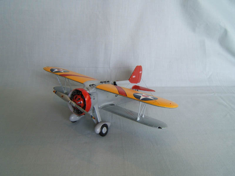
The kit comes in a soft cardboard box with a nice drawing of a Sparrowhawk flying in the vicinity of the airship on the box top. The bottom of the box gives us a colour scheme of all the Sparrowhawks serving on board the USS Akron an Macon. The kit itself contains 4 frames with 52 parts in light grey plastic and a nice decal sheet providing two options and all the bureau numbers. A clear acetate sheet is provided for the windshield.
We are dealing with limited-run kit quality with flash, seams and sink marks galore which makes building that model very labour intensive.
Surface detail is rather limited and existing panel lines are recessed or raised in parts. No rivets anywhere.
There are hardly any cockpit details. This certainly lends itself to a lot of scratchbuilding. Since the cockpit itself it rather spacious for such a small aircraft one can later see quite a bit of detail added in the process.
Getting Started
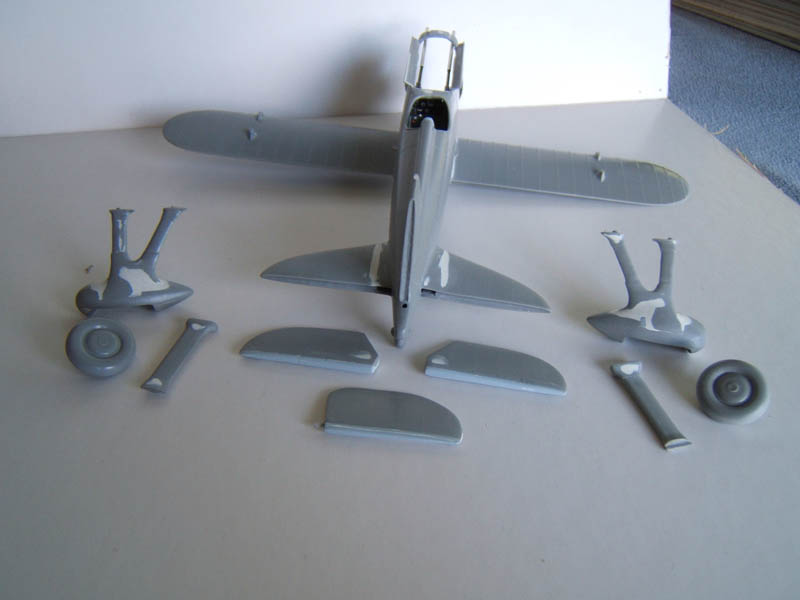
The first thing I did was to separate all parts from their respective frames, organized these into sub assembly lots and started removing flash injector pin marks (where necessary) and dealt with all these sink marks by using Tamiya filler. As one can imagine, these preparations took quite some time.
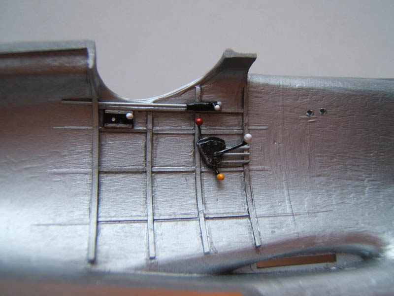
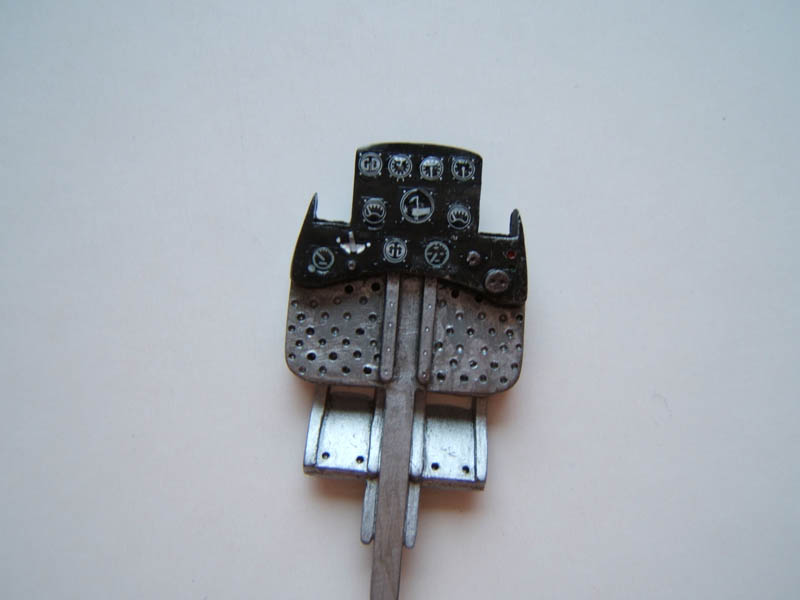
When this was done I moved on to scratch-build the cockpit interior (except seat, cockpit floor and instrument panel) using some Sparrowhawk cockpit photos I found online. I used the instrument panel supplied and drilled all the recesses for the various flight instruments with a conical drill bit (dental technician's tools). Switches were made from scrap plastic.
The decals for the flight instruments are not from the decal sheet supplied, but were cut out from decal sheets I have in my stash.
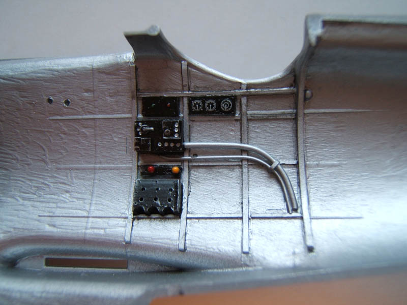
The radio equipment, various switch boxes, throttle quadrant plus the instrument panel on the starboard cockpit wall were made from scrap plastic (of which I keep an ample supply exactly for jobs like that). The levers, knobs and handles were made of stretched sprue.
Ribs and stringers were cut from Evergreen Strip.
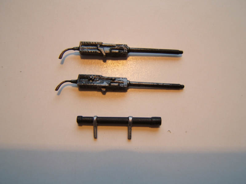
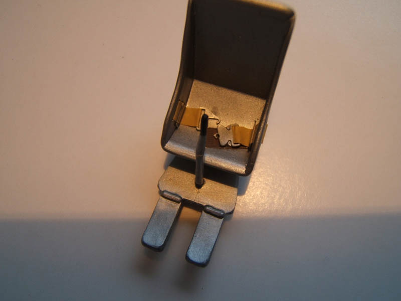
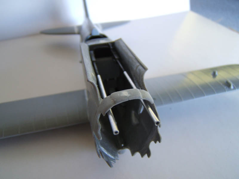
The machine guns are actually of a 1/48 Monogram B25 Mitchell and the blast tubes were cut from thin aluminium tubing. The seat harness was made using Tamiya masking tape, the buckles I used were of a car seat belt set (if I remember correctly).
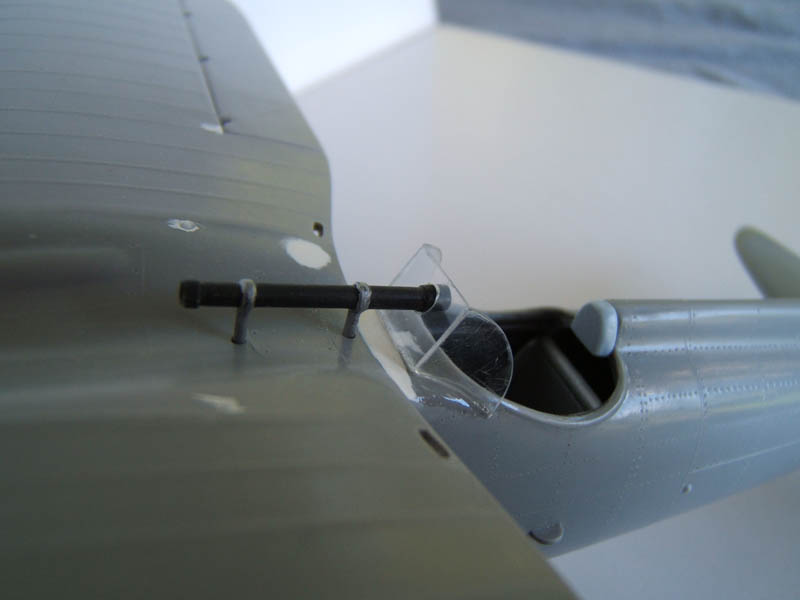
The kit supplied gunsight was no good and I made a new one from scratch. The windshield is made of clear Evergreen sheet and the pitot tube and venturi tube are also home made.
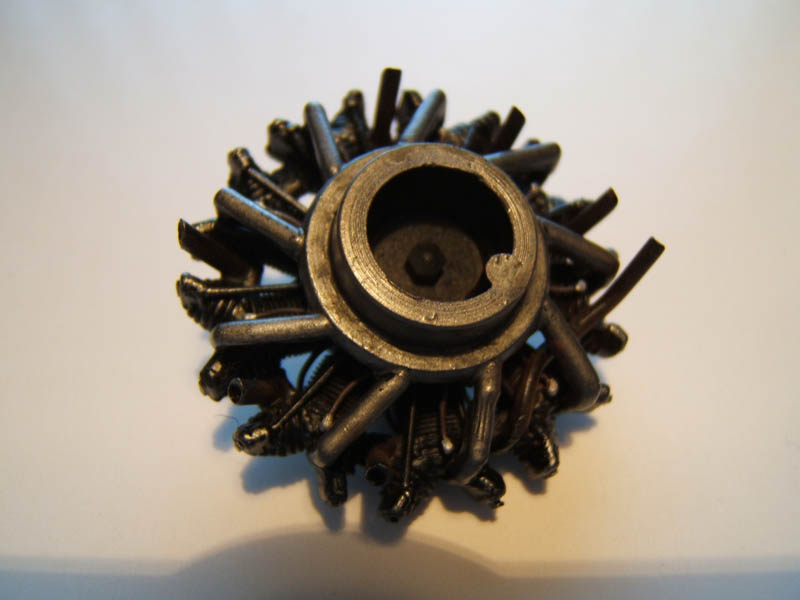
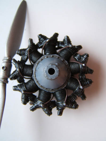
The propeller hub was absolutely useless and I decided to scratch build this item. I cut off the propeller blades and carefully glued these into recesses in the new hub making sure that the pitch alignment was the same on both blades. The radial engine was another matter. The actual cylinders are fine. The have quite finely moulded fins. But the cylinder heads were awful. Rather coarse (more like bulges). To remedy this to some degree, I carved and deepened the grooves in between these 'bulges' to get a bit more refinement. But there was only so much one could do in this case and the cowling is hiding this to some degree.
The ignition leads were made from stretched sprue.
The exhaust stacks were drilled hollow to give them a more realistic look and the top cylinder exhaust was made of Evergreen polystyrene rod.
The intake manifold needed a lot of cleaning up and careful bending to make sure the intake tubes were in even contact with the attachment points on the cylinder heads.
The cowling ring halves went together well and dry fitting this part to the radial engine revealed the ring was too loose. To make sure that the cowl could be easily installed I cut small spacers from Evergreen strip and glued these onto the cylinder heads in order to get a better fit. The result was a nice slight interference fit between cowl ring and engine, which made it a breeze to install the painted cowl with a bit of super glue.
Having taken care of all the scratch building I moved on to painting the cockpit and engine. While the paint was drying I kept on going with assembling the wings and the landing gear legs and spats. To fit the wheels and axles into the spats was another arduous task.
Surgery was done to separate the elevators and the rudder. Evergreen strip and putty was used to build up the leading edges of the rudder and elevators to a more rounded shape to make these parts fit nicely into the recesses cut into the tail plane and fin.
That done I glued the cockpit and the guns into place and closed up the fuselage.
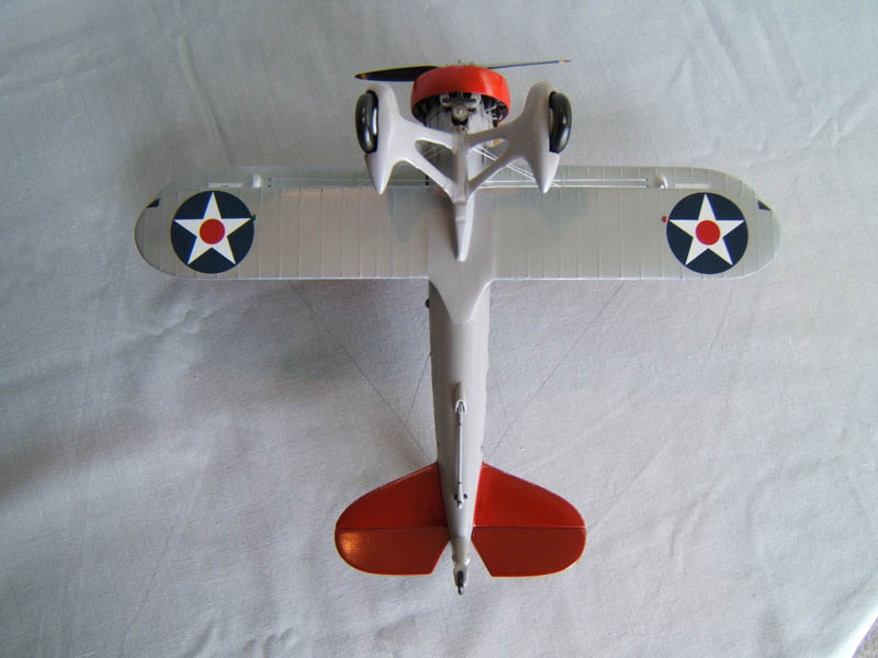
The seams had to be cleaned up with some putty but the overall fit of the fuselage shells were not too bad. At that stage the lower wings and tailplane were glued into place. Again, as can be seen on the photos, quite a lot of filler had to be used to fix gaps at the joints.
Important is to make sure that the lower wings have zero dihedral.
A lot of dry fitting had to be done to fit the engine assembly into the recesses on the forward fuselage. In order not to ruin the paint I used a toothpick inserted into the reduction gear casing as a sort of handle to move the engine.
Since there is very little panel line detail evident (some recessed, some raised) and comparing these details with the photos on the Sparrowhawk Walk Around Website, we find that the original had numerous raised rivet lines all over the fuselage and tail plane. I used the sketches on the instruction sheet to mark these rivet lines and, using a home made tool, engraved these rivets one by one on the fuselage, fin and tail plane. This itself was very time consuming as one can imagine, but it was well worth the effort.
Another small modification I did was to drill 2 holes at the forward part of the bulged part of the lower fuselage. These are the location for two drain pipes (I guess for petrol and oil tank). These drain pipes were later added using Evergreen rod.
Now it was time to glue the landing gear assembly into place and attach the compression struts. The instructions show at what angle they need to be fitted.
The wheels and axles needed dry fitting to slot them into place at the right angle; ie position these so that the landing gear is shown in a on-the-ground position. To achieve this, the spats needed to be widened a little to space for the wheels and avoid contact with these once the wheels are in place.
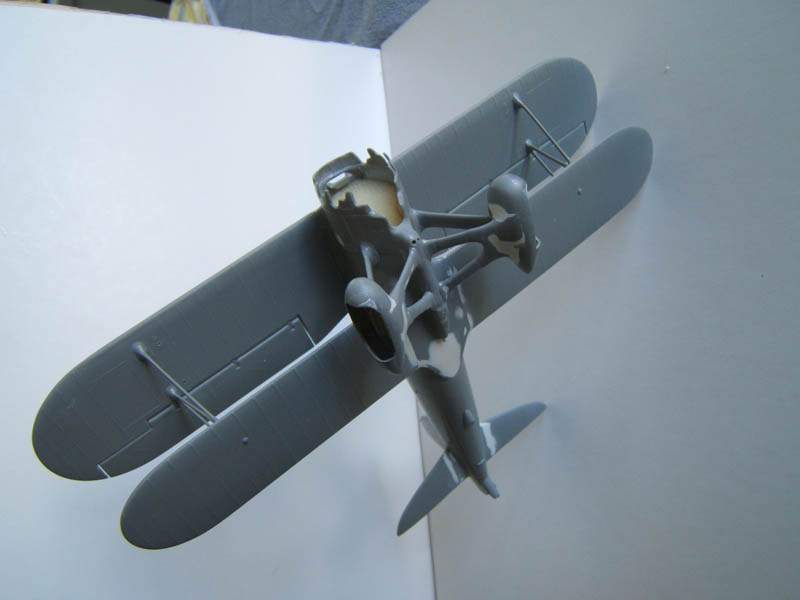
Before the upper wing was fitted to the fuselage I drilled all the holes for the rigging wires and the holes on the outer upper wing for the antenna masts. The upper wing assembly required dry fitting to make sure the the alignment of upper to lower wing was correct. A lot of remedial work was necessary to get the forward panels right (large gaps had to be filled and reshaping the panel out lines had to be done.)
The good part was that the gaps underneath on the interface between wing and fuselage were minimal – pleasant surprise here! Note: the upper wing has a small 3 degree dihedral.
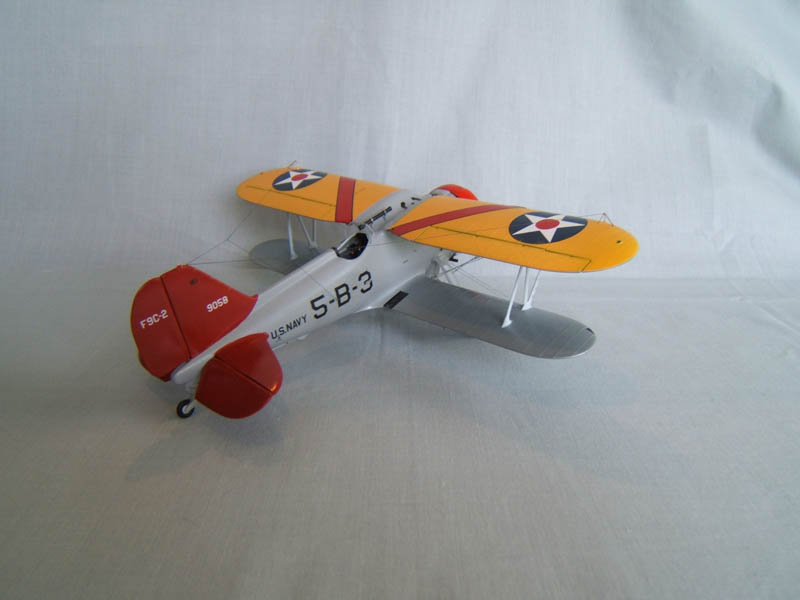
Since I decided to do a 'what if' variant of the Sparrowhawk serving on a carrier I had to fill the holes for the attachment points for the 'skyhook' frame.
The N struts were another problem. I had to make spacers to build up the bases for the struts (the N struts themselfes were a tat short.) Again, this took a lot of time; measuring and a lot of dryfitting was necessary to remedy this, making sure that the dihedral stayed the same on both sides.
The pitot tube was made of Evergreen rod and narrow strips of masking tape were used to secure the pitot tube to the N strut.
With the upper wing in place and the upper center wing decking all cleaned up I dry fitted the scratch built windshield before gluing it into place. The telescopic gunsight was test fitted to assure proper alignment with the opening in the windhield.
The windshield frame was hand painted, left to dry and was carefully masked off before I started to paint everything else.
The Paint Job
I did this in the following sequence:
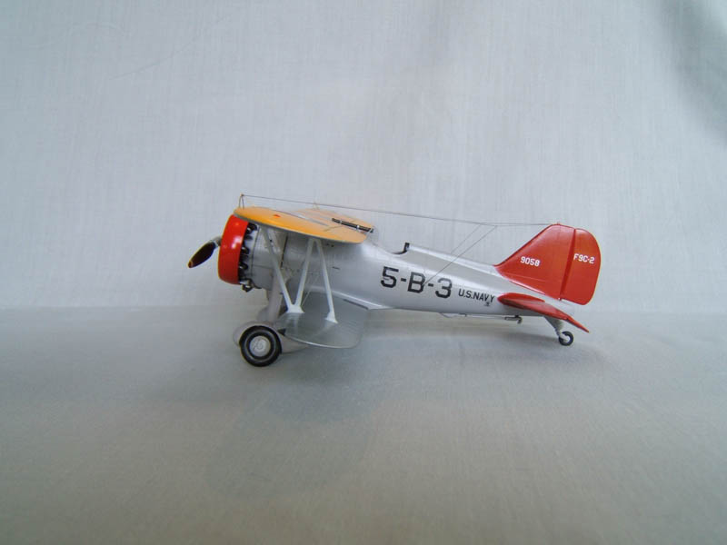
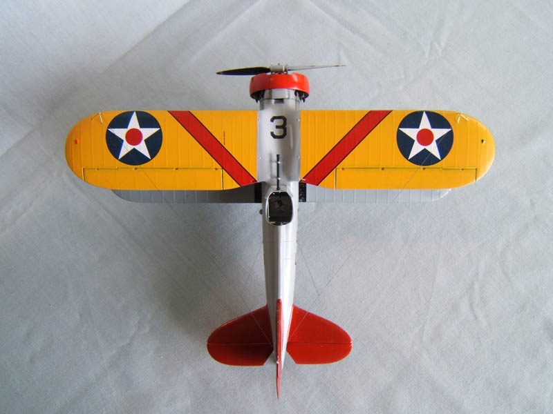
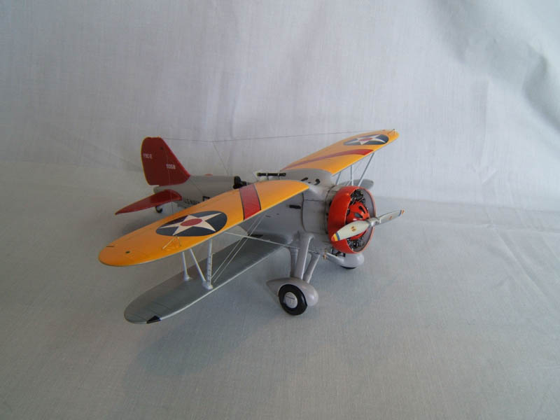
- Paint the N struts with Tamiya XF-19 (sky grey), leave to dry and mask these before moving on to paint the upper wing in orange yellow (Tamiya XF-3 flat yellow and a tiny amount of Tamiya X-7) and a clear coat of Tamiya X-22 on top.
- Paint all the upper wing undersides and the lower wings with Tamiya X-11 chrome silver and a top coat of X-22.
- Paint the cowling ring and the fin/rudder and tailplane elevators with X-7 (red)
- Mask off tail plane and fin, upper and lower wing and proceed to paint the fuselage and landing gear in XF-19 sky gray (I added a bit of Tamiya flat white) and a thin coat of X-22 clear.
- Tyres, venturi tube and telescopic gun sight were painted in matt black and the wheel hubs in sky grey.
Finally it was time to remove all that masking tape, touch up small spots where necessary.
The rigging was done using flexi line (Wingnut Wings supplied that). Before super gluing these into place I made sure that paint was removed from the holes. I you do not do this beforehand, the superglue is dissolving the paint to some degree and does slow down the CA setting time.
With the rigging in place, I carried on with the decals.
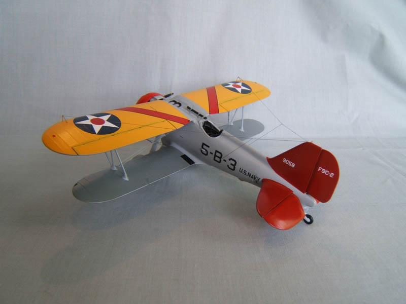
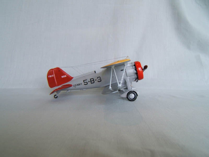
As I mentioned before, the markings are fictional and might have appeared as such on Sparrowhawks serving aboard on of the early carriers.
After the decals had dried thoroughly I gave the model a overall thin coat of X-22 to seal the decals and applied a very moderate amount of weathering around the fuselage behind the engine.
The final step was to cut small pieces of guitar string to make the tripod antenna masts and Ezi Line was used to do the antenna wires.
Conclusions
This kit is not for the faint hearted. It requires a lot of patience and a certain amount of scratch building experience to get the best out of this kit. But I'd say it is well worth it to get stuck into this project in order to create a model of one of the rarest US Navy biplanes ever in service.
© Michael Rohde 2018
This article was published on Wednesday, August 22 2018; Last modified on Wednesday, August 22 2018