
21st Century Toys P-38J-15-LO “Lucky Lady” in 1/18 Scale – Part 7
By Jay Wheaton
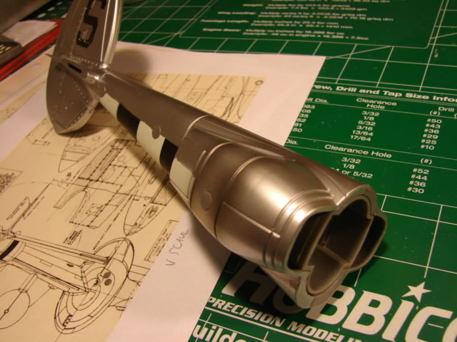
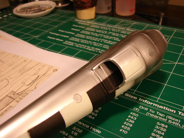
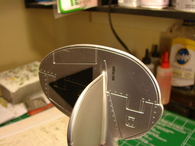
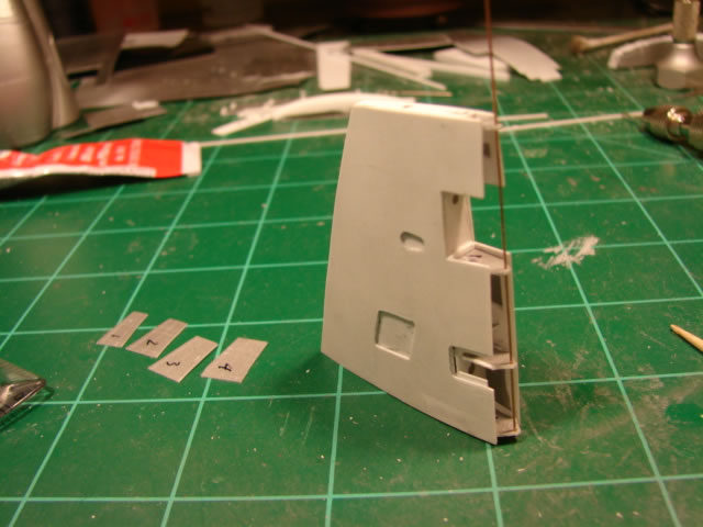
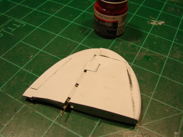
Welcome back to the Lucky Lady build (check out Part 6). In this part I will show how I updated the tail booms and empennage. The tail boom work essentially revolved around the large radiator housings, or fairings. I could not do much with the shape, which is not quite right, but I could improve the intake and outlet areas. Here are a couple of shots of the unmodified housings:
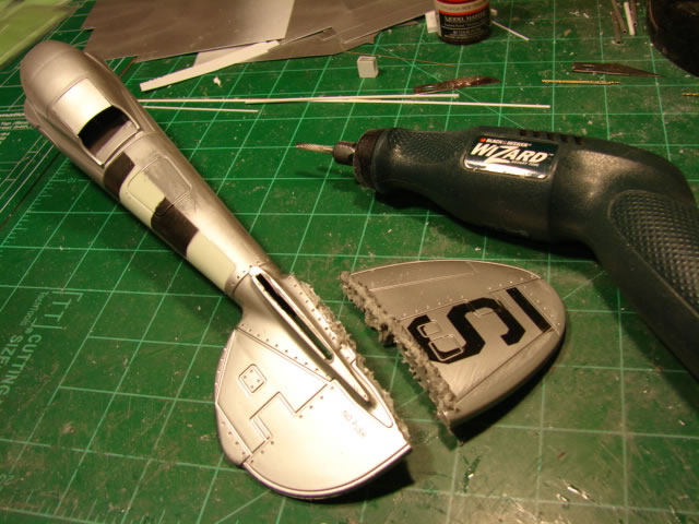
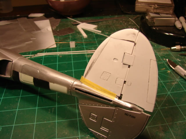
I basically did three modifications – new panel lines, a scratch built outlet flap or door, and slots for the inlets. Not sure why those slots were there on the actual aircraft, but they were there. Panel line work:
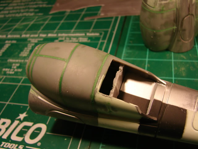
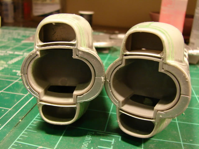
And addition of material to simulate the slots:
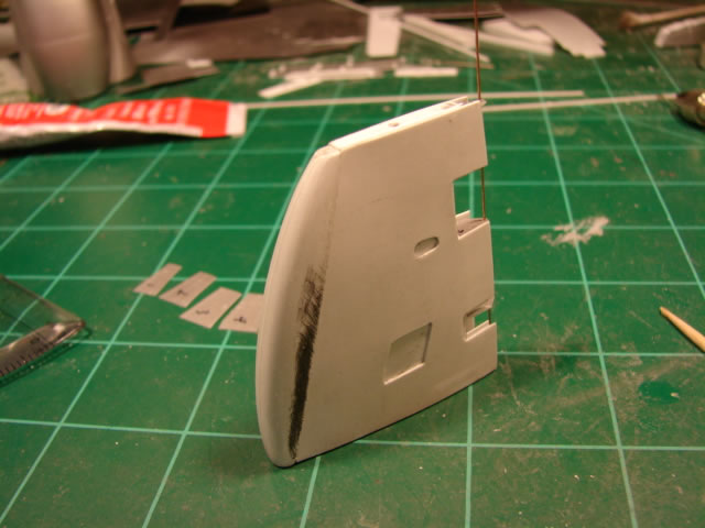
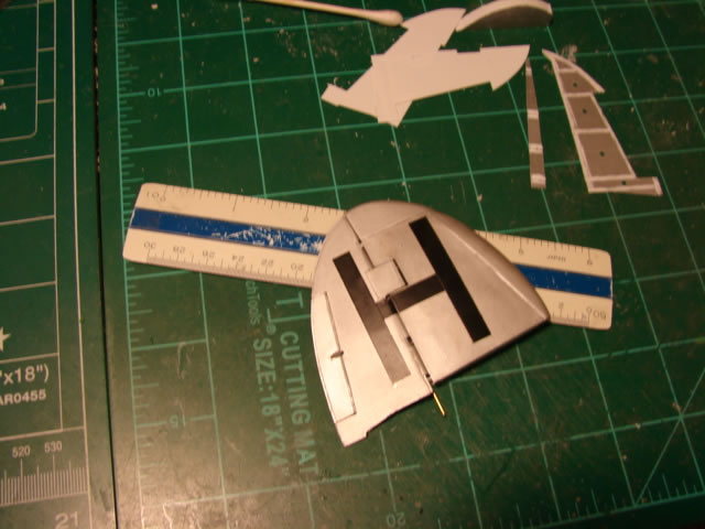
That was pretty minor stuff; the real challenge would be the tail surfaces. Take a look at the unmodified tail:
I don’t know – should I really be disappointed in this? It’s a toy. Anyway, I needed it to look real, so it had to go:
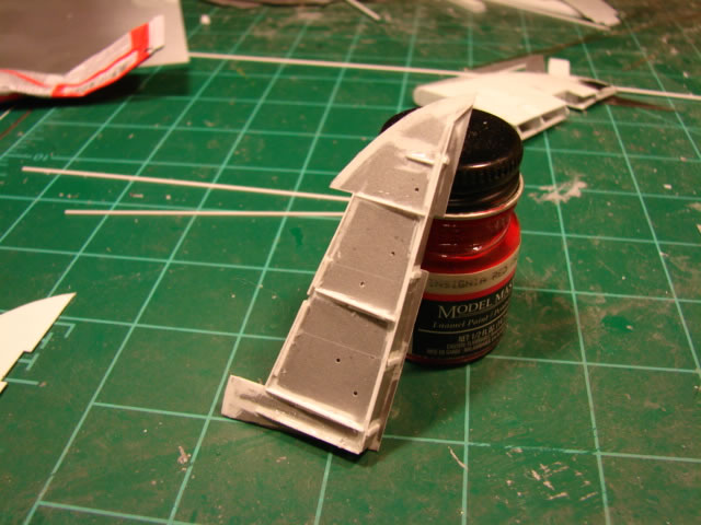
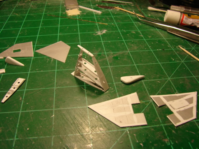
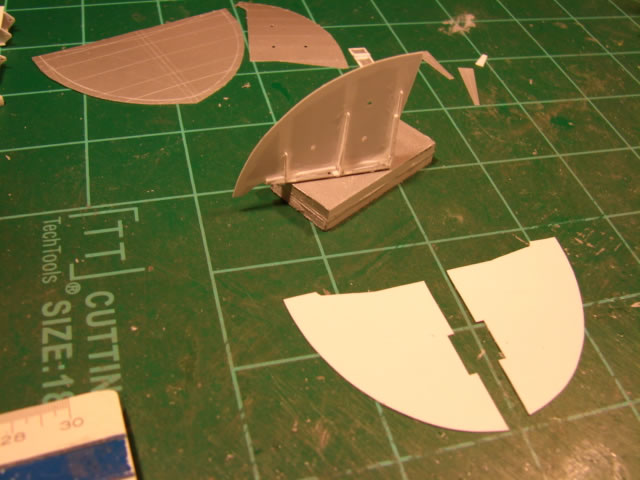
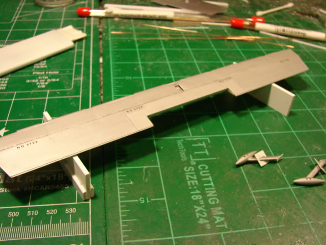
The vertical tail(s) would be scratch built then, something I had never done before. My plan was to have separate rudders of course, and skin and frame fin boxes, with hinge ribs and fittings, hinge pins, and shaped solid plastic leading edges and tips. Here is some early work on the upper fin box:
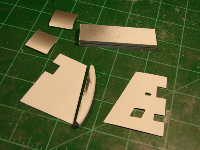
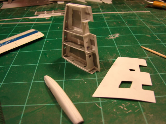
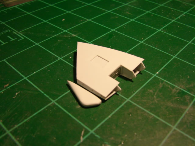
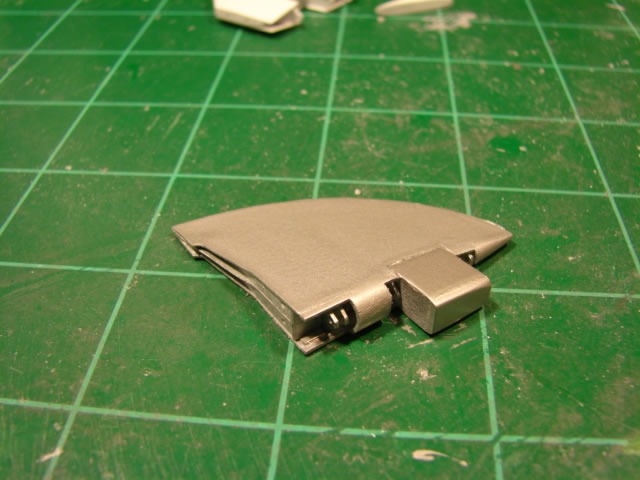
The LE fairing was the hardest by far, being cut and sanded out of thick plastic. The finished fin box:
You can see the hinge pin inserted through the several hinge ribs. This all benefited of course from detailed computer modelling. The same approach was done on the upper rudder, although the shape is so different as to make the build very different as well:
Here is an essentially finished upper rudder:
You see the balance weight, round section LE fairings, access doors, hinge ribs, and the tab. This was a pretty cool (and time consuming) project.
Put them together and you get this:
A dry fit yielded some fit-up issues, but nothing disastrous:
Shimming the fin box fixed it. Now the lower fin and rudder had to be built. Fin work:
That strange looking lower tip fairing is shaped that way to provide a tail skid. It was not fun at all to shape that little thing!
Next in line was of course the lower rudder:
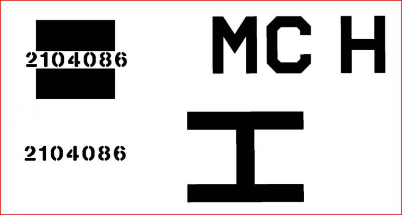
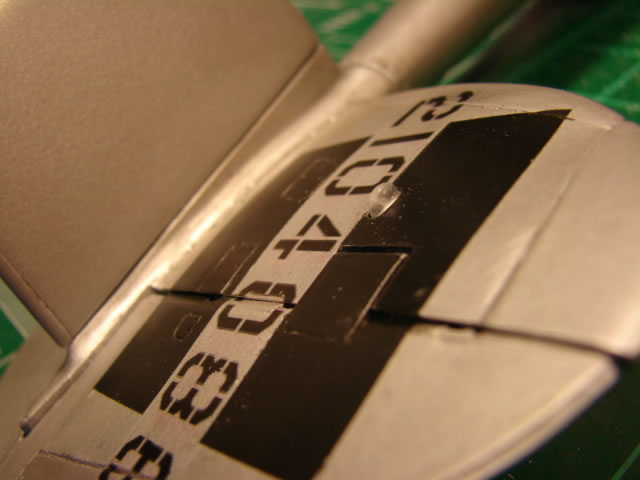
Although I do not have a shot of the dry fit to the tail boom, the fit was pretty good (better than the upper fin/rudder). At this point (LH vertical tail complete) it became necessary to create the decals for this 20th FG aircraft. No problem; just black letters and numbers. Here is an early version done in PowerPoint (I made some minor changes later on):
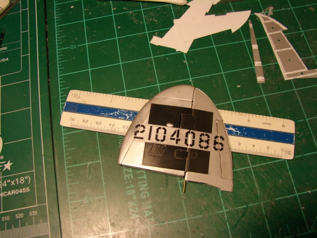
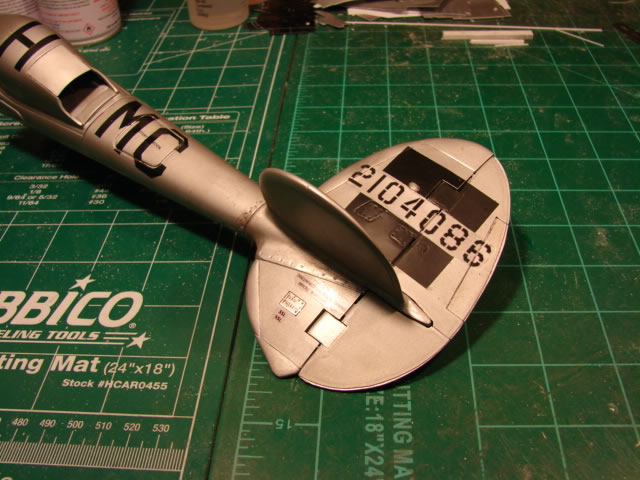
After paint and decal application the vertical tail looked like this:
I was at this point a very fired up modeler. The vertical tail plan had risk, and it turned out good. Here, the LH vertical tail surfaces are final installed onto the tail boom:
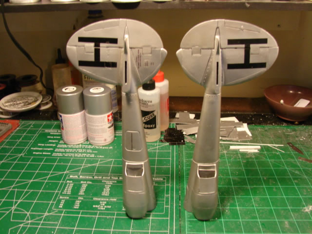
After duplicate builds for the RH side, I took shots of the completed tails:
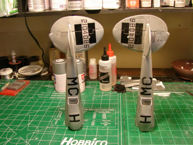
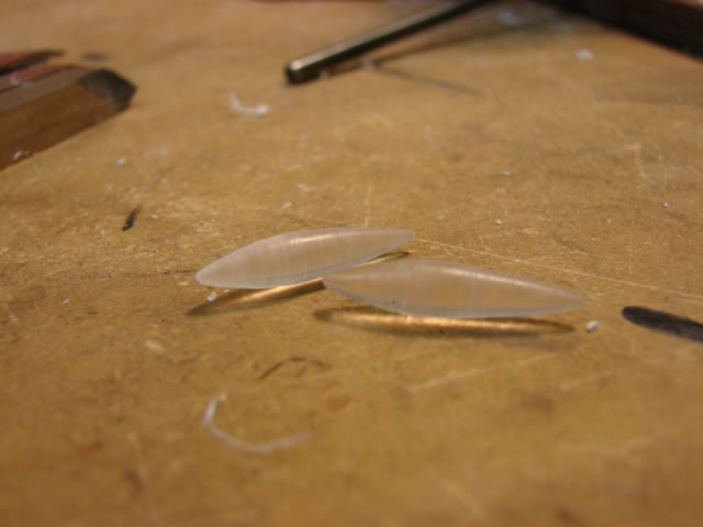
But was I really done? No – they needed anti-collision lights. I filed these out of some chunks of clear acrylic. I needed six! Two for the tail, and four for the wings. Little PITA’s.
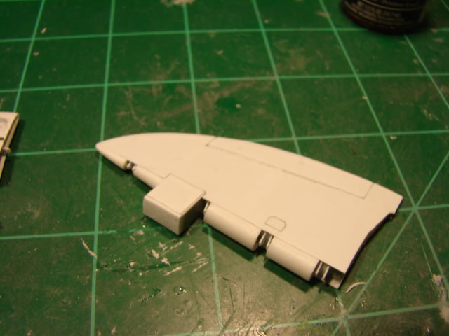
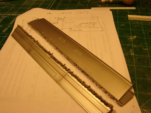
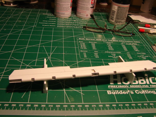
With the vertical tail and booms done, I focused my attention on the horizontal tail. It needed some serious work. Here are a couple of shots of the unmodified unit:
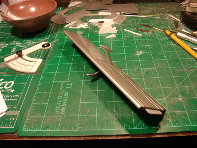
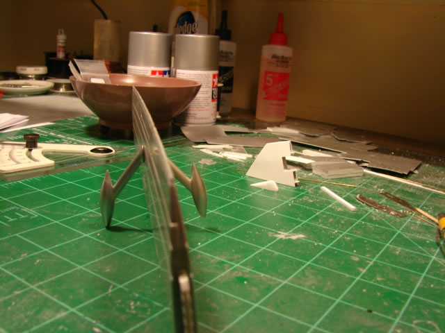
Note that in addition to the lack of realism, there was a significant warp. Also the elevator balance weights were about 50% larger than they should be. Why? Who knows. But I had to fix it:
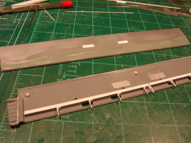
At this point it dawned on me that a scratch built stabilizer box would be really tough, mostly because I might not be able to make a convincing leading edge that was constant aero section over the entire span of the stab. I could make a lumpy one, but not a smooth one. So I tried a couple of ideas, each of which failed, and instead decided to keep the stab section and scratch build the elevator. So, off comes the existing elevator:
Separating the hstab upper half from the lower half was typically harrowing work. The glue they use is really effective and care must be taken to not harm the parts, nor my own body parts. Once successfully separated, I could add in a scratch built rear spar of sorts, with hinge ribs:
That work was all rather simple, for a change. The elevator would not be simple at all. Here I have gathered together a whole bunch of detail parts that would make up the elevator assembly:
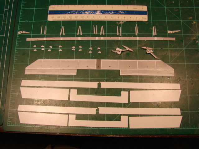
You see skin panels, inspar ribs, hinge ribs, spars, and the new balance weights and towers (I will show more on them). Built up, the elevator box looks like this:
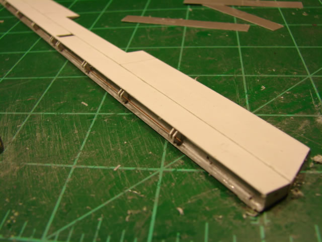
See the brass wire hinge pin? Add the LE nose fairings and it looks like this.
By the way, the LE nose fairings, like the rudders, are made from simple plastic round tube sanded to a semi-circle section, and cut to length. Works great.
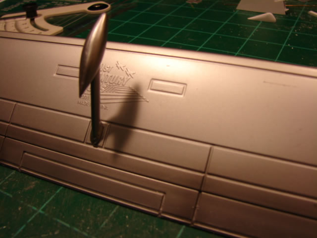
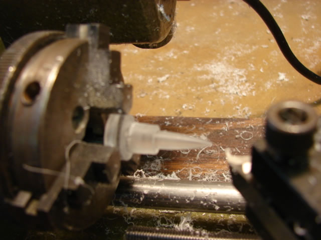
So how did I make new balance weights? With the lathe of course! Look:
Built up with towers and fake tower attachment bolts, and skin doublers, it looks like this:
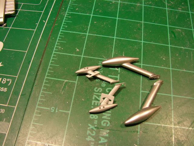
Note the size difference between old and new. My balance weight towers protrude thru the skin and attach to a center plate, in addition to the skin doublers. Very sturdy, and similar to the real thing.
Lastly a couple of shots of the nearly complete and painted elevator (minus tab, and balance weights not yet attached):

Installation of the elevator to the stab section yielded some mismatches that I do not have pictures of. What a disappointment; it was a result of some sloppy computer modelling. But standard modelling skills took care of it for the most part.
That is all for now. Next installment, part 8 (which will be the last), I will take us through the outer wing modifications including scratch building the ailerons, and shots of the completely finished P-38. Please stay tuned!
© Jay Wheaton 2016
This article was published on Wednesday, October 26 2016; Last modified on Wednesday, October 26 2016