
21st Century Toys P-38J-15-LO “Lucky Lady” in 1/18 Scale – Part 5
By Jay Wheaton
Last we saw Lucky Lady in Part 4, she had a greatly improved cockpit and forward canopy and windshield. Now to get the rest of the center fuselage into shape. Let me say something here – panel lines were a problem on this rebuild. Existing lines, even if in the right place, were “trenches” and had to be redone, if possible. In some cases, panel line restoration was so difficult as to make the end product worse than the original. That was the case on the nose piece. I wish I had the skill to have done that. Other panel lines on the complex shaped center fuselage were nearly as tough. OK that said, let’s get down to business.
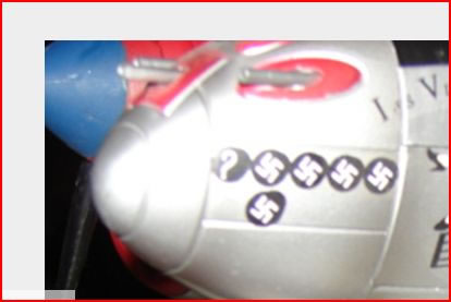
The original toy had a fairly poor representation of the machine guns and cannon. Take a look:
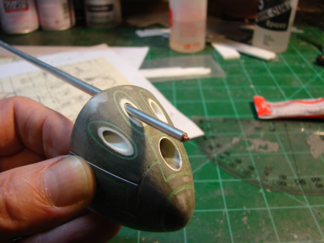
My plan was to create properly sized and shaped holes in the nose, and then scratch build machine guns (MGs) and cannon with various sizes of aluminum and/or plastic tubing, centering them in the holes with spacer tubes. There was risk that this might go very badly – something I had no plan for if it did, except to find and buy another 21CT P-38! Here is a shot of the hole drilling, done on the mini-lathe (in drill press mode). The nose piece was clamped tight, and then big holes were drilled very very carefully.
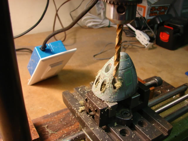
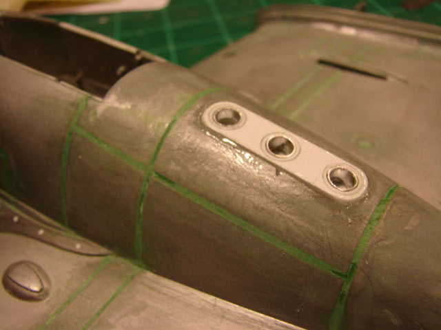
Look like it could go wrong? I thought so! But those drill bits are really big and stiff, and behaved very well. The holes are sized to receive plastic liners and then the guns. Here are untrimmed liners glued in the holes:
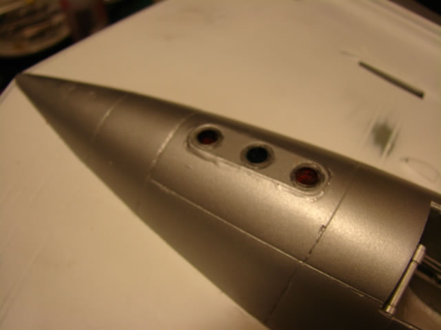
Trimming was easy, and gave some really nice holes (and a big sigh of relief):
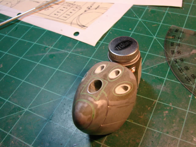
I will fill you in on an error - the big hole for the cannon (the hole in the center) is effective on G-models (maybe H-models too) and previous. Later variants had a smaller hole in the nose fairing panel. But I didn’t realize that until I was already done. So I accepted it and moved on.
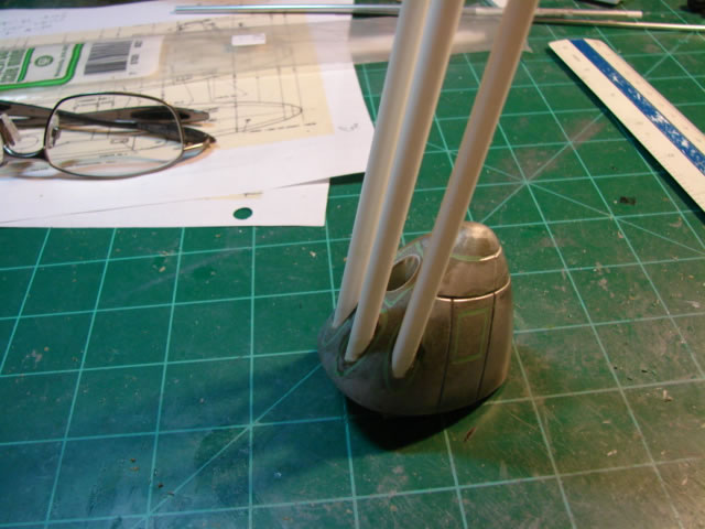
The MGs were made from various sizes and materials of tube stock, selected to best scale the actual size of the guns, including a spacer tube whose OD matched the ID of the hole in the nose, and whose ID matched the OD of the blast tube. Got that? It is hidden inside the hole, and is supposed to center the MG in the hole. It worked! Like this:
Do same for the other three MGs and the cannon, and you get this:
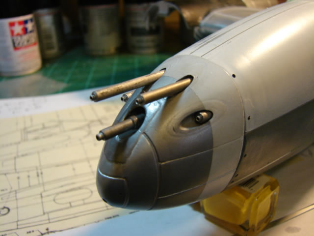
Note I do not have the perforated blast tubes. The J-model and subsequent had the solid ones for reasons I don’t know. Good, that would have been a gigantic challenge.
Now was the time to tackle yet another challenging sub-project on the center fuselage – the remainder of the canopy. Here is the toy part, which isn’t that bad but it isn’t quite the right length, and obviously lacks realism:
I had been fretting about the aft canopy because it is “compound curved”. When I scratch build canopies, I am limited by “singe curvature”. By that (apologies to those who already know this) I mean a surface that curves in only one direction. That is as opposed to “compound curvature”, which curves in two directions. A piece of paper (or thin plastic sheet or aluminum sheet) can be formed to single curvature. But to give it compound curvature takes a vacuform or drop-hammer die or some such thing where stretching of the material can be done. I do not have such a tool nor the skills to work with it.
The side windows of the forward canopy are single curvature, where the windshield posts form the axis about which curvature can be forced into the thin clear plastic sheet. No big problem there. But the aft canopy glass is compound curved, at least slightly. That is because the center line spine is curved itself, along with the aft canopy frame. So it was my hope that the clear plastic sheet was soft enough to give at least an approximation of compound curvature.
Enough of that… Here are the two structural pieces of the aft canopy:
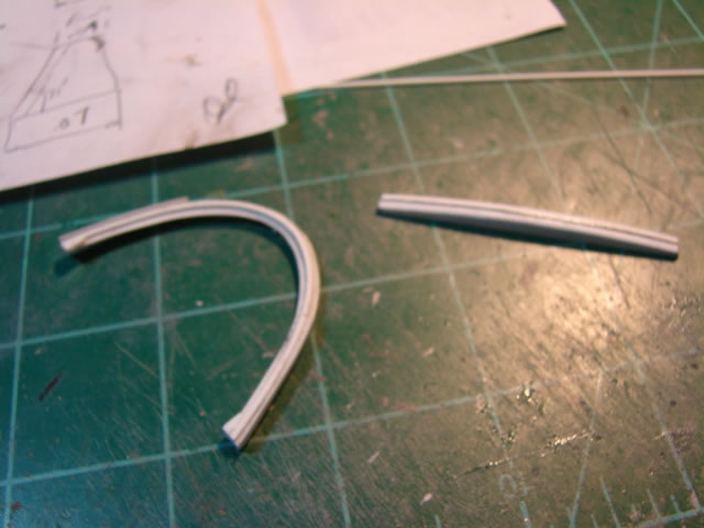
Nothing earth-shaking here other that getting the shapes just right (computer modelling once again). You can see that slightly curved centerline frame, or spine.
Here are those parts installed:
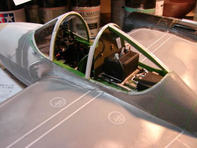
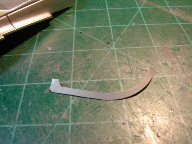
Now for the glass. Computer modelling allowed me to cut pretty accurate flat patterns. Here is a test panel made of white plastic:
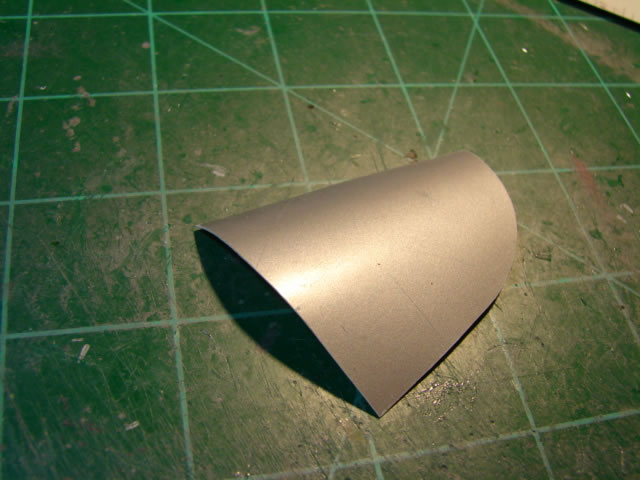
An attempt was made to form this part in two directions. It doesn’t want to do it, let’s just say.
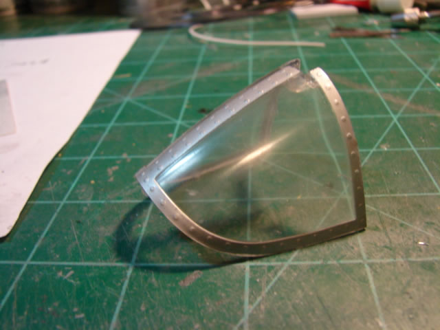
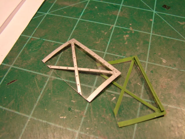
Here are the clear parts:
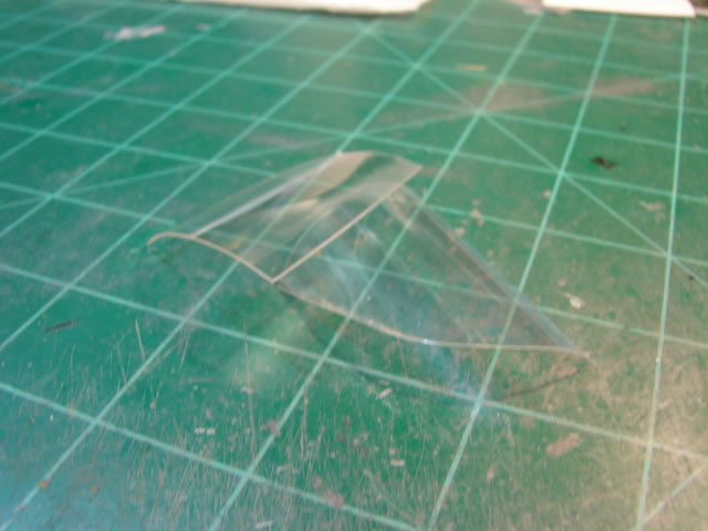
These parts resist compound curvature even more than the white part – I think the clear plastic is somehow stiffer and more brittle. You can see I formed some curvature, but it is not compound. I would rely on the curved centerline frame to provide that. Like this:
The middle of each panel pooched in just a touch but believe me – I declared victory.
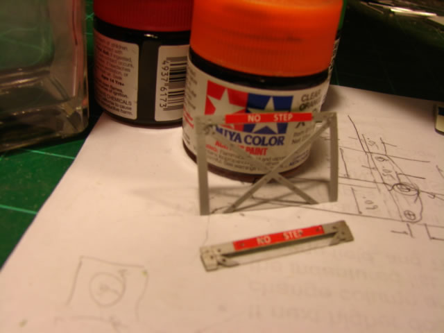
What can really make or break an effort like this are the strips that outline the windows. Computer generated flat patterns helped enormously:
Here is the aft canopy with all the strips present:
The only part of the canopy I did not scratch build was the top hatch, as I mentioned earlier. However it looks nothing like the original part. Its bottom edges were ground straight (were curved) to be more accurate, strips added, and a hinge mechanism added. Here:
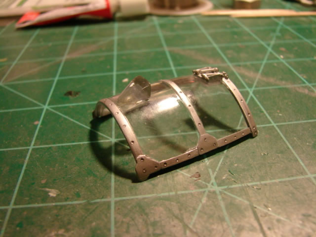
You can also see the clear rear view mirror fairing, which I turned on a lathe and extensively machined and filed afterwards. Scratch built side windows were easier. These would fit in slots built into the canopy frames. I decided to have the option of showing a window cranked down – all I did was make another window and slice most of it off:
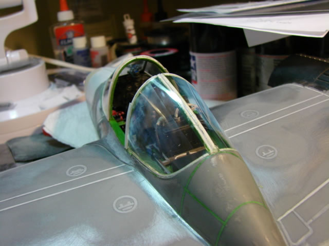
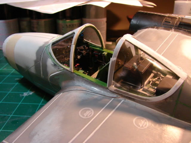
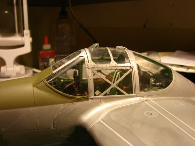
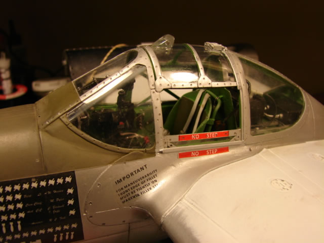
The finished canopy looks like this:
Compare to the original:
I hope the differences are plain to see. I believe the scratch built version is infinitely more accurate and convincing. That was absolutely required to make this thing look like a P-38. I was a very happy camper.
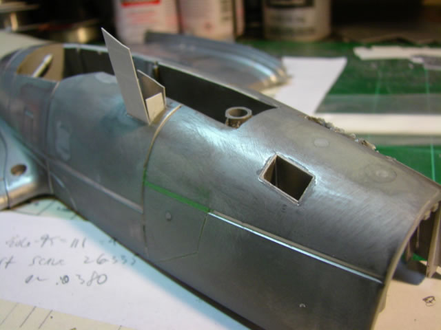
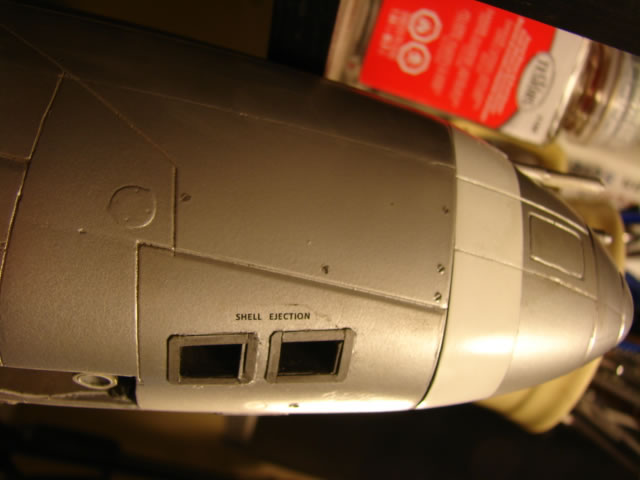
There were other inaccuracies to deal with – shell ejector chutes and ID lights were the worst of them, along with some difficult panel line work. Here is some shell ejector chute work, where I basically Dremmeled away the old, and scratch built the new:
Did same with the ID lights:
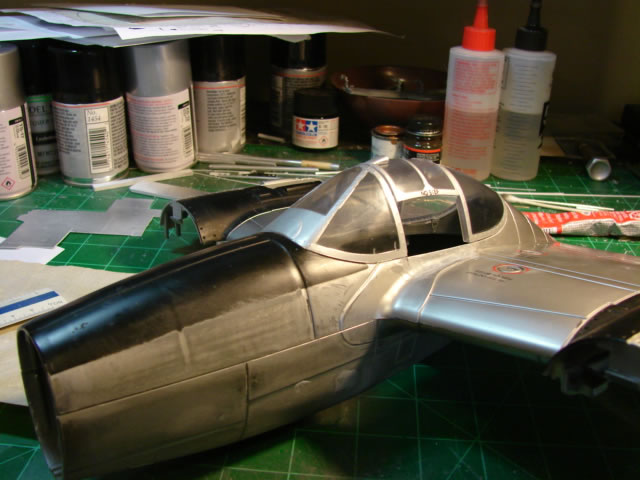
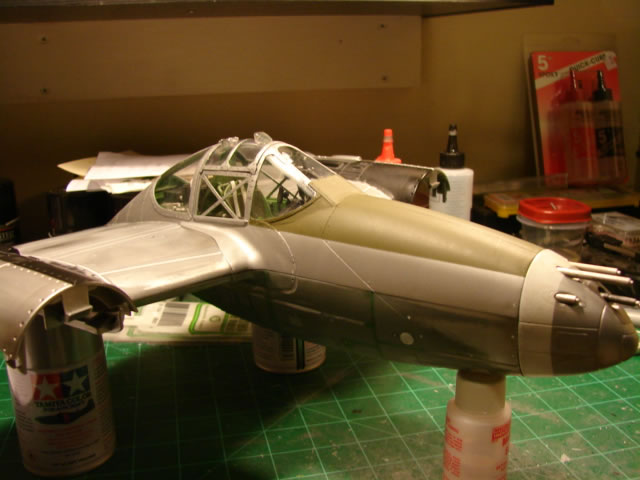
This was starting to really look like a P-38:
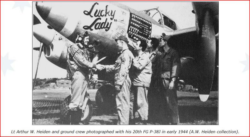
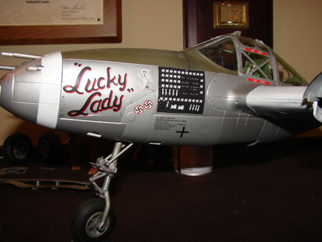
I wanted to paint the center fuselage as a separate unit, and apply the nose art and other decals. Part of the reason why I selected “Lucky Lady” was that I believed I could reproduce the nose art and scoreboard. Here is a period photo that was very helpful:
The scoreboard would be fairly easy – just create little shapes (sort of like emojis!) in PowerPoint, shrink down, and repeat as necessary. Then create the names in script. The nose art however would be very tough. I basically blew up that period photo and literally created pixels that approximated the letter shapes, in large scale. When shrunk down, the decal looked very sharp. Stack a black one on a red one, shift a touch, for the shadow effect, and voila! Here is the decal sheet:
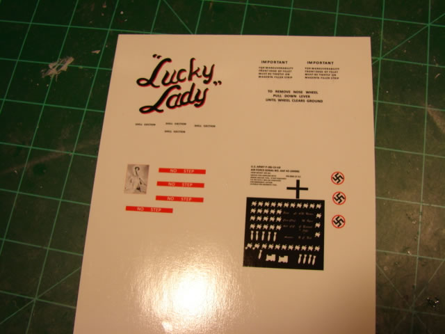
You will also see a small photograph of actress Lorraine Day, who had some sort of wartime patriotic relationship with the crew of Lucky Lady. I conducted a web search but could not find the exact photo, but found one similar.
These decals (the large ones) were difficult to get right. But here is the center fuselage basically done:
Canopy too:
Ejection chute and ID light details all done:
You can perhaps imagine how pleased I was to complete this part of the model.
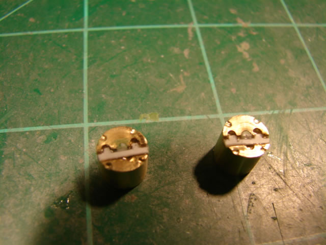
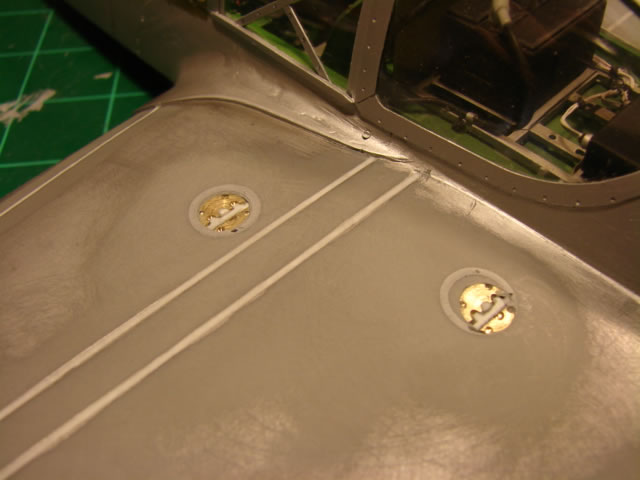
Then it was on to the inner wings. Only panel lines and the fuel filler caps were really issues. The bomb pylons would come later. Here, you see lathe-turned fuel filler caps, installed in drilled holes in the upper wing. I elected not to salvage the existing fuel filler caps, because they were…pitiful.
That will do it for this installment. Part 6 will show the (soul destroying) work I did on the engine cowlings and their installation onto the center fuselage and wing, maybe more. Thanks for looking in!
© Jay Wheaton 2016
This article was published on Wednesday, September 14 2016; Last modified on Wednesday, September 14 2016