
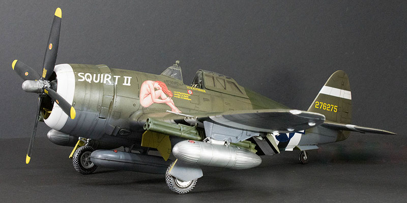
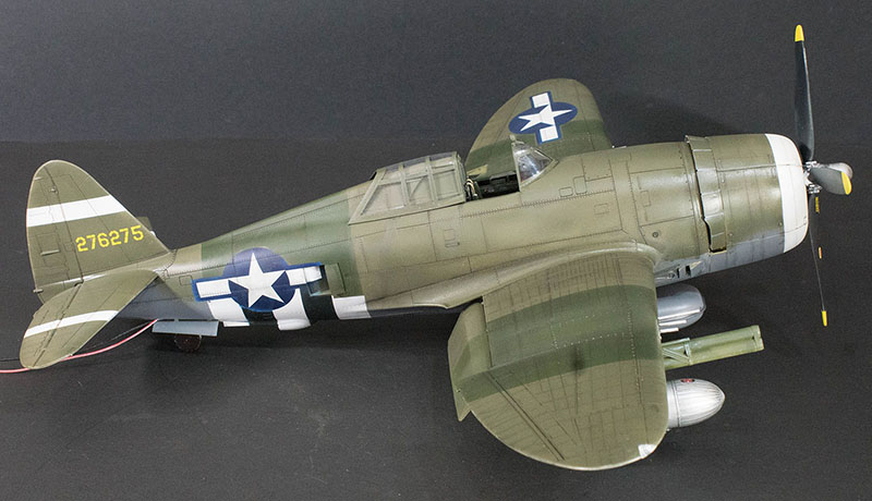
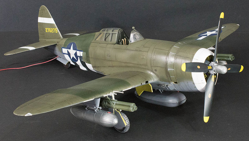
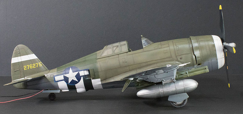
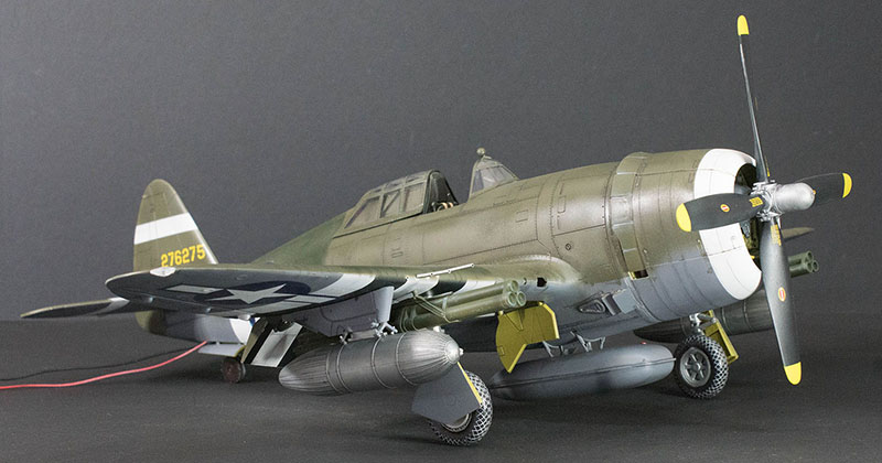
Kinetic 1/24 P-47D Razorback Thunderbolt
By Michael Benolkin
Materials used in this build:
- Kinetic K3208 1/24 P-47D Razorback Thunderbolt kit
- Airscale PE24TBT 1/24 P-47D Instrument Panel Upgrade
- HGW Models 124506 1/24 P-47D Pilot Seat Harness
- MRC 02500 Light Genie
- Assorted LEDs, resistors, wire, fiber-optics
- Master Casters MST24004 Open Cowl Flaps and Weighted Wheels
- Evergreen 9002 Styrene Odds and Ends
- K&S 320 Tube Assortment
- 3M Acryl-White Putty
- Mr. Surfacer 500/1200
- Montex K24049 P-47 Paint Masks
- Aizu Micron Masking Tape (0.4mm, 0.7mm, and 1.5mm)
- Tamiya Acrylic paints
- AK Interactive panel line washes
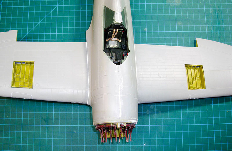
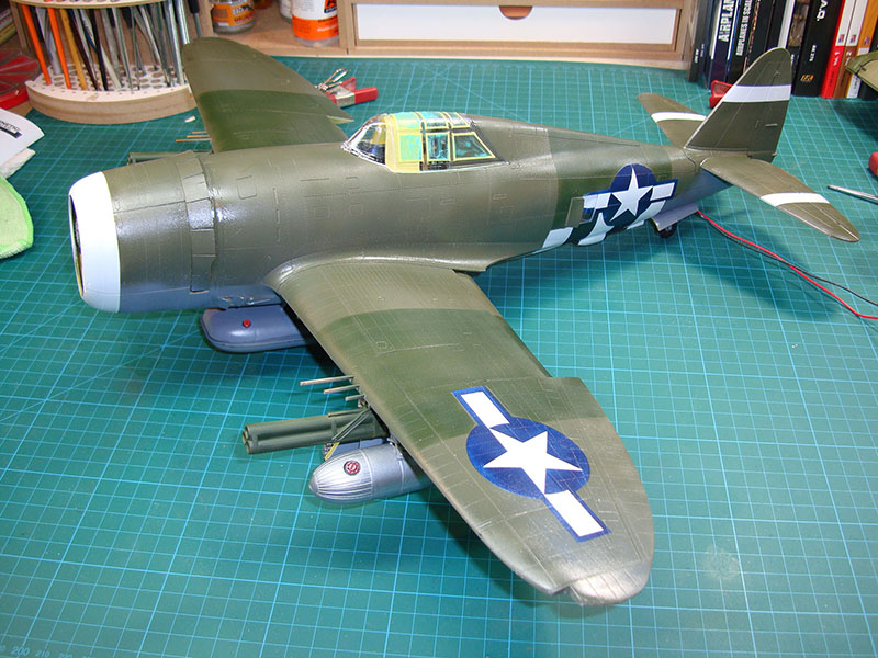
As mentioned in our first-look at this kit, Kinetic has obtained the molds for the Vintage Fighter 1/24 P-47 Thunderbolt kits (this razorback as well as the bubbletop) and have reissued them under their label. The kit isn't complex, it is just large. After doing the first-look, I set this aside and set about the task of obtaining certain aftermarket sets to do my build and the last missing item arrived yesterday. I will be publishing this build in increments and we'll have a list of aftermarket items used in this build should you wish to something similar. I won't be posing this aircraft with panels open (perhaps a gun bay) but I will be trying out a few things to see how they work.
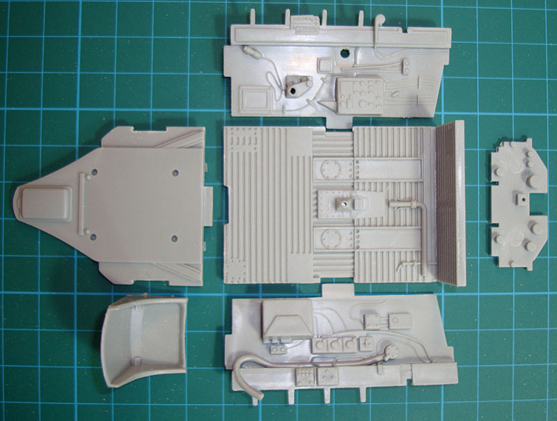
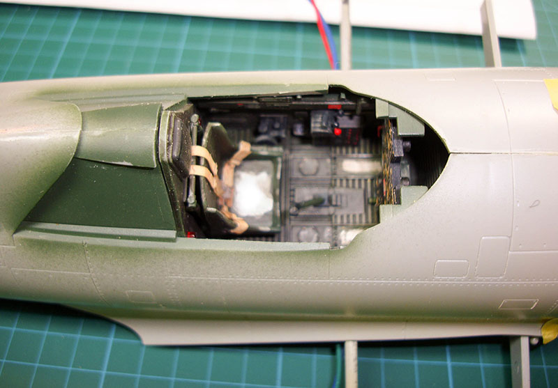
As with most aircraft kits, construction begins with the cockpit. I removed the major parts from their sprue trees and you need to pay attention as there are parts for the bubbletop variant in this kit so don't get them mixed-up. I removed the sprue stubs, mold lines, and a few ejector pin marks, then decided to dry-fit the cockpit tub together. There are no surprises here and the fit is good. There's going to be some time spent in here between painting and detailing as the cockpit is the showpiece of most aircraft builds.
While I was dry-fitting things in the kit, I wanted to see how these two huge fuselage halves fit and there is no warpage or other fit problems here.
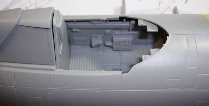
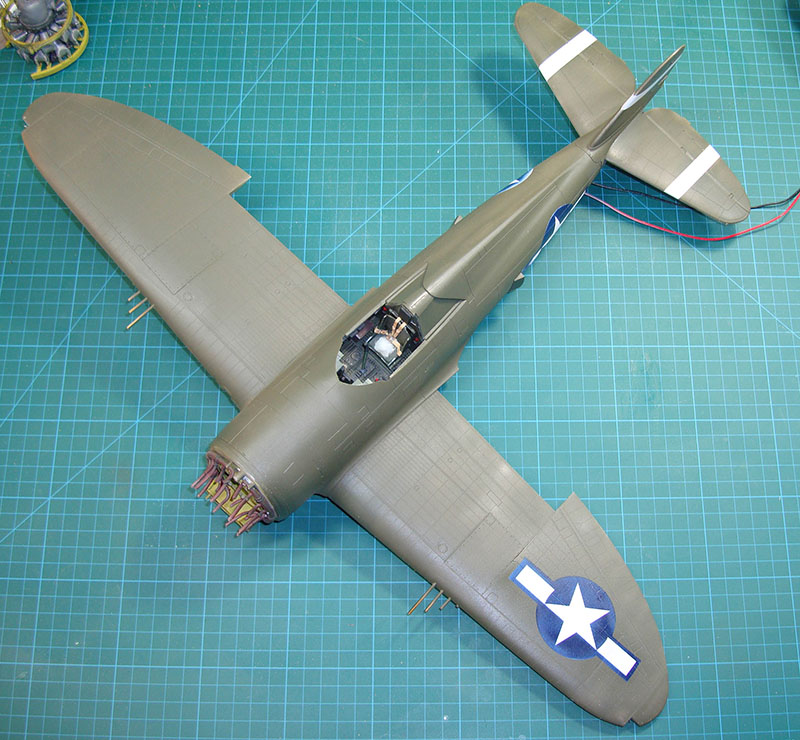
I also wanted to see how this cockpit sits inside the fuselage but there was no good way to get it into place without the main spar assembly that sits below the cockpit. I dry-fit that assembly together, mounted the cockpit atop of it, and closed up the fuselage halves. You can see just how much of that cockpit is going to be visible with the canopy open so we will be spending some time in here.
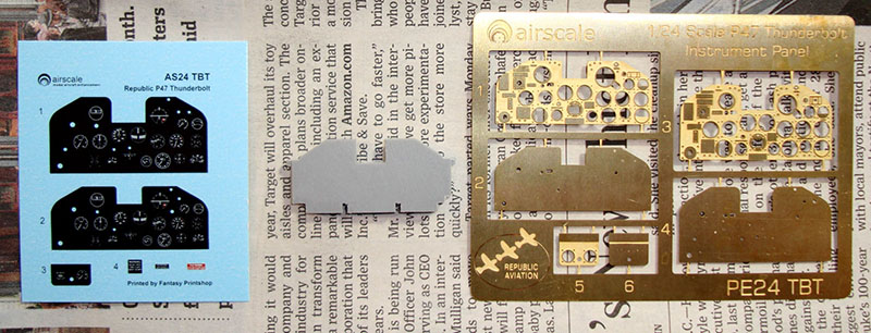
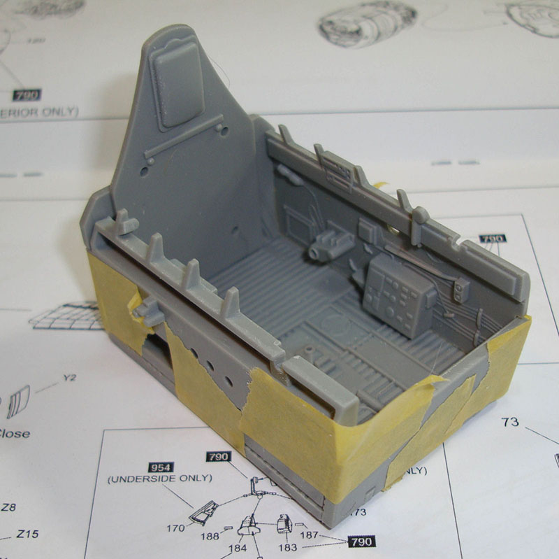
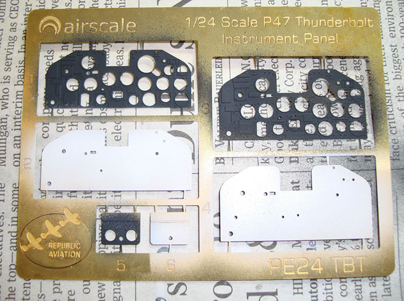
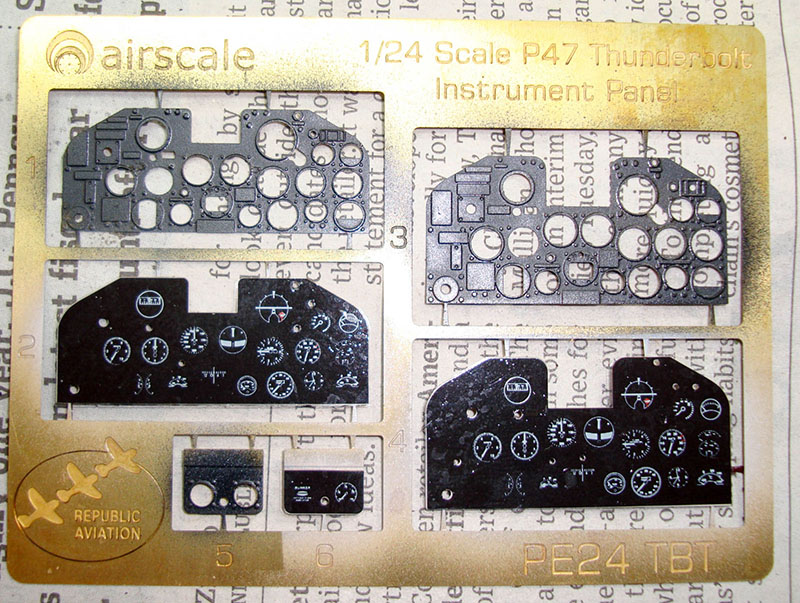
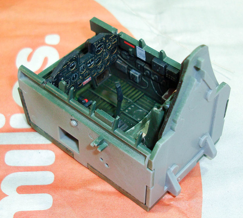
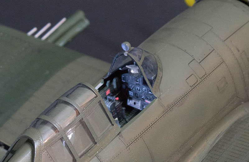
One of the aftermarket items I wanted for this build is a new instrument panel. The kit panel isn't bad, but I thought it was a bit shallow. Here is Airscale's solution, a photo-etched backplate for the decals to sit upon and a three-dimensional relief photo-etched overlay to go over the decals. The gray kit part is in the center and I've already removed the molded-on details. The smaller instrument panel provided in the Airscale set is designed to be the same size as the kit panel but with some additional surface details. The panel on the right is also designed to fit in the Kinetic/VF cockpit but it is proper scale proportionally (taller). A small sub-panel for the right side is also included.
One of the techniques I wanted to try is the 'chipping' technique where you apply an undercolor, spray the chipping fluid over the undercolor and immediately apply your base color over the chipping fluid. In this case, I wanted the bare metal to show through the foot wells for the rudder pedals. I applied AK Extreme Metal Aluminum, and after it had dried, I applied their chipping fluid and then the cockpit base color. Once I had the airbrush cleaned, I 'wore' through the base color and chipping fluid to expose the bare metal. I'm still not happy with this yet, but I have lots of weathering to do before this cockpit is finished.
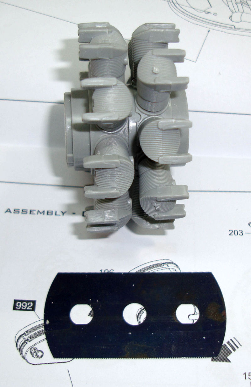
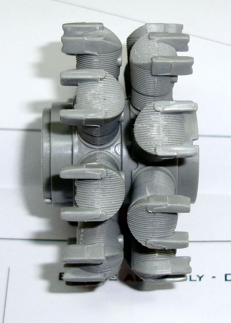
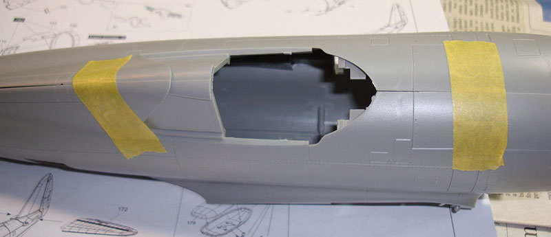
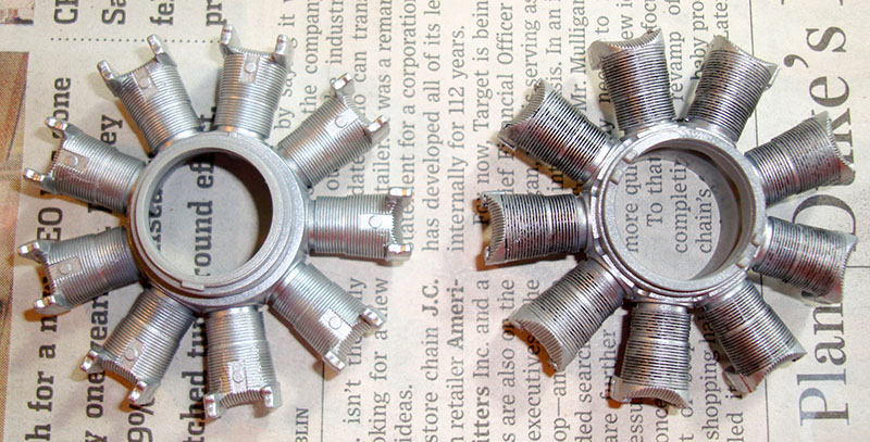
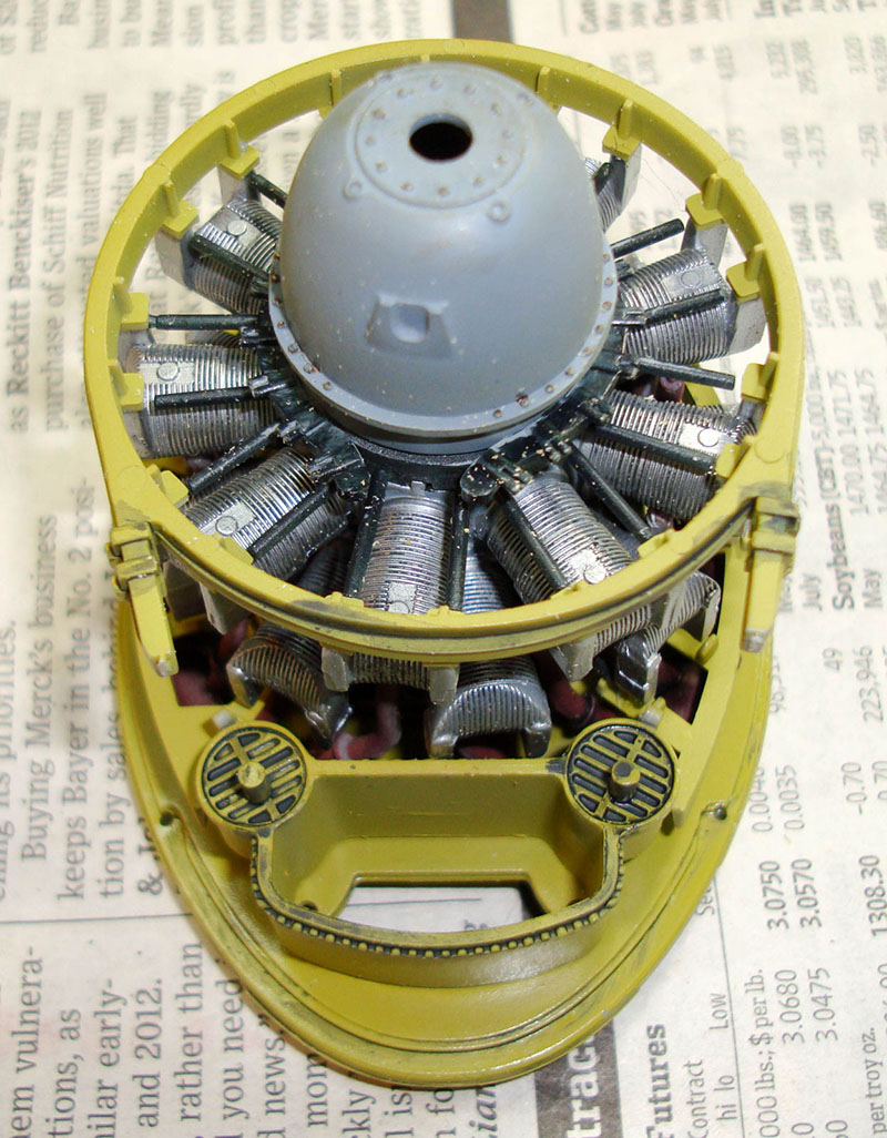
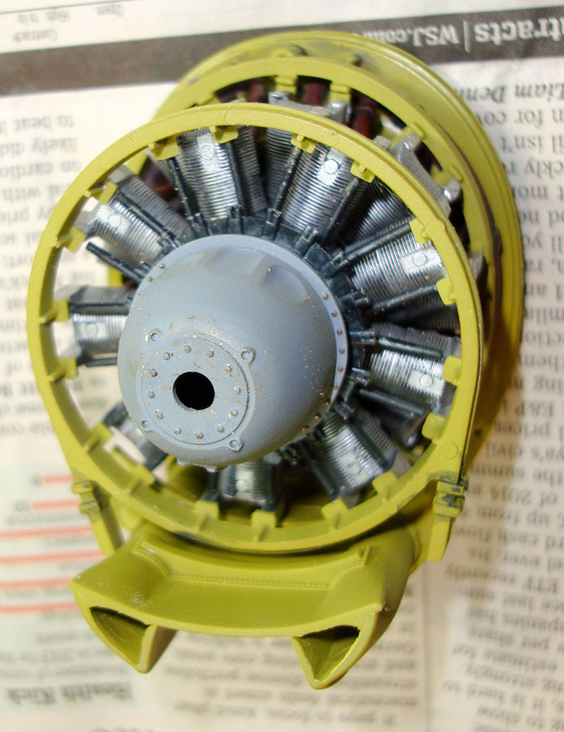
While the cockpit was drying, I decided to start on the next major feature of this build - the engine. Each bank of cylinders is molded as one part which is a molding feat of its own. In the first photo, I've cleaned up the bank of cylinders on the left while the right bank still has some mold lines and sprue stubs still in place (left photo). I carefully filed away the mold lines on each cylinder head as well as the sprue stubs atop some of the cylinders. I used a razor saw to add cylinder fin details where the sprue stubs used to be to bring all of the details together (right photo).
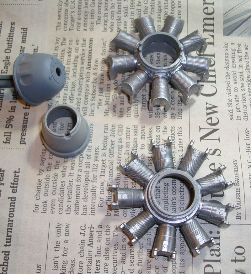
I sprayed the crank case halves and gearbox cover an engine gray while the cylinder heads were painted aluminum. Once these are try, I'll hit those nice details on the cylinder heads with a black wash to make that detail pop out.
Moving back to the cockpit, I painted the instrument panels Tamiya NATO Black and the panel backs white per the instructions so that the white instrument details in the decals with stand out better.
I applied a coat of Future to the photo-etched parts so that I could apply the instrument faces to the white background and the placards to the black overlay. The instrument decals are in place here and look quite nice.

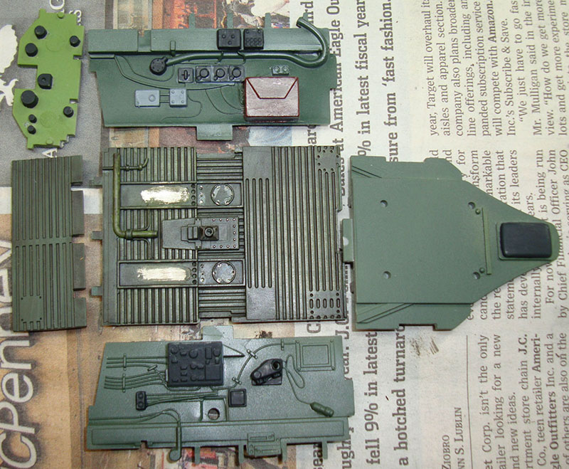
Here's the cockpit floor after some weathering. I used the AK Interactive wash for green camouflage and covered the floor part. Since the paints are acrylic and the wash is an enamel, there are no issues with one interacting with the other. Once this was dry, I grabbed a lighter green than the original base color to dry-brush highlights in certain areas. Here is the floor with the other cockpit parts that are still receiving detail painting but have not yet been washed to show the contrast.
Taking a break from the cockpit, the engine is ready for the next step. The bank on the right has received a wash of lamp black oil paint to bring out that nice cylinder head detail. The bank on the left is next but shows the contrast with and without effective washes. If you haven't made your own washes before, here's a tech tip to show you how.
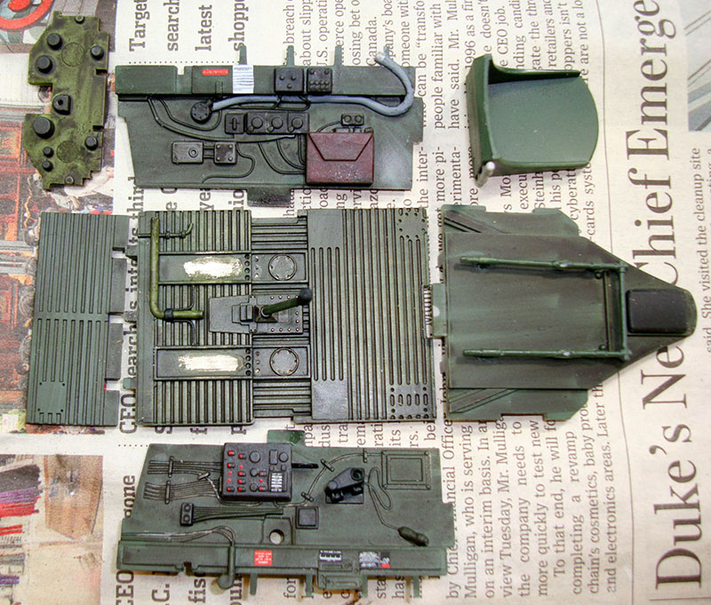
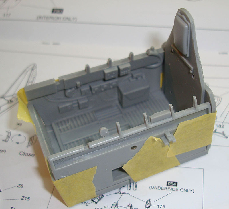
Here is the cockpit tub with stenciling added and the same weathering used on the floor applied to the sidewalls and rear bulkhead. The seat is next.
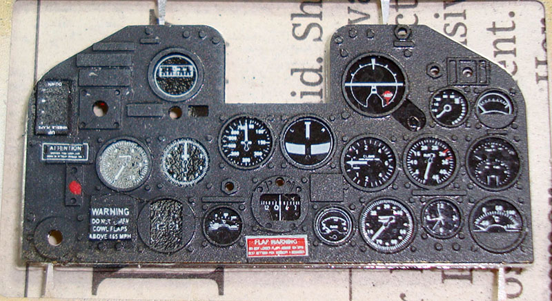
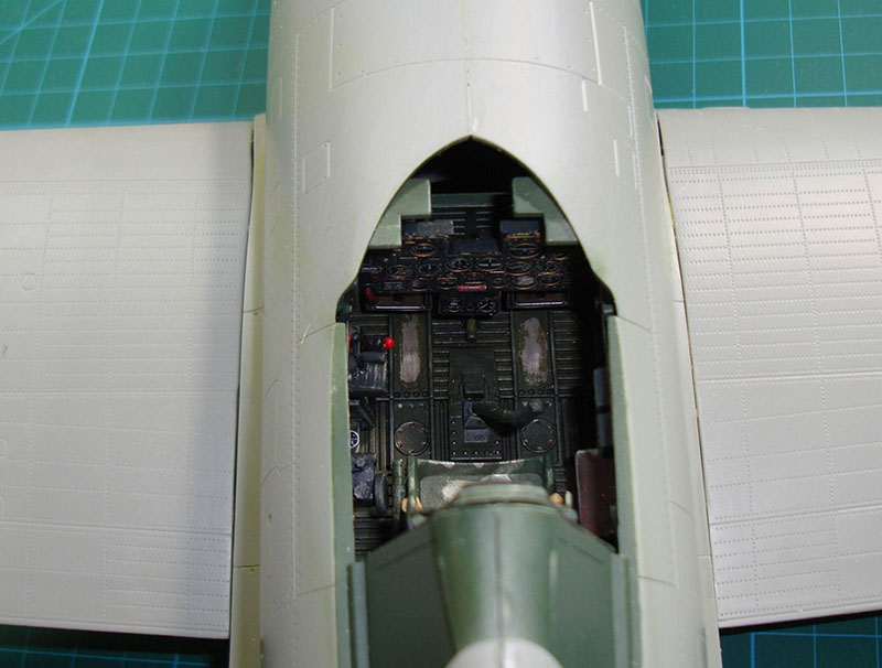
This is what the Airscale instrument panel looks with the stenciling applied and sitting atop the instrument faces. The Airscale set includes a sheet of clear acetate to simulate instrument glass but I opted to apply a layer of Future to the entire decal face and laminate the photo-etched instrument face over the decals using the Future as the adhesive. You can see holes in the instrument panel where knobs and switches are intended to be placed. Since there are none included in the Airscale set and none in the Kinetic kit, I used fiber-optic strands with the tips heated into knobs and other materials to fill these voids.
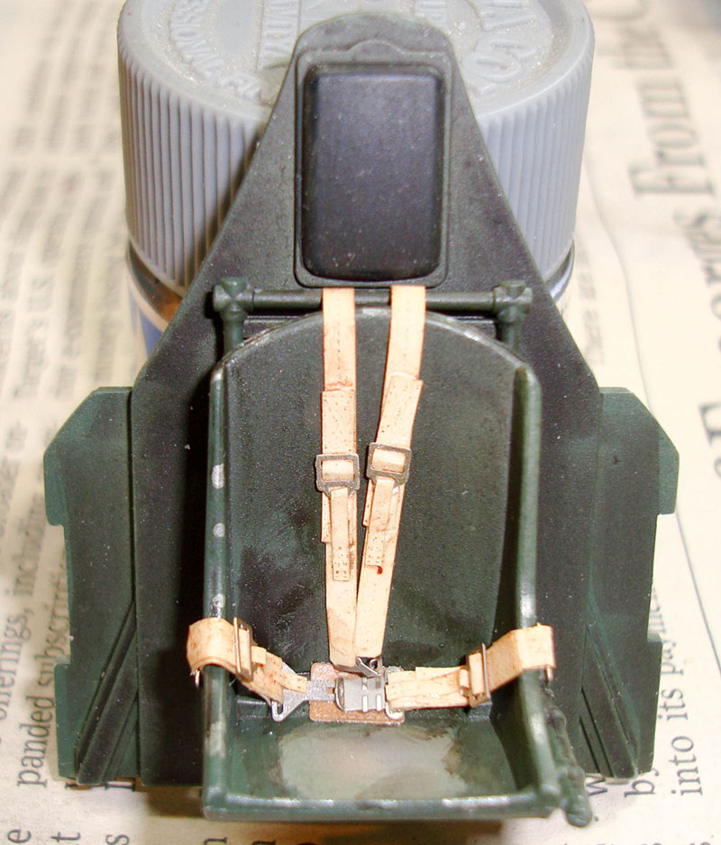
The pilot's seat is now weathered with the seat bottom worn through the paint from the wear of the parachute pack (and attached pilot) shifting around during flight. The kit doesn't provide for pilot restraints but here is the HGW Models 1/24 P-47D harness set consisting of fabric straps and photo-etched hardware. This beast took some time to assemble but the results look great.

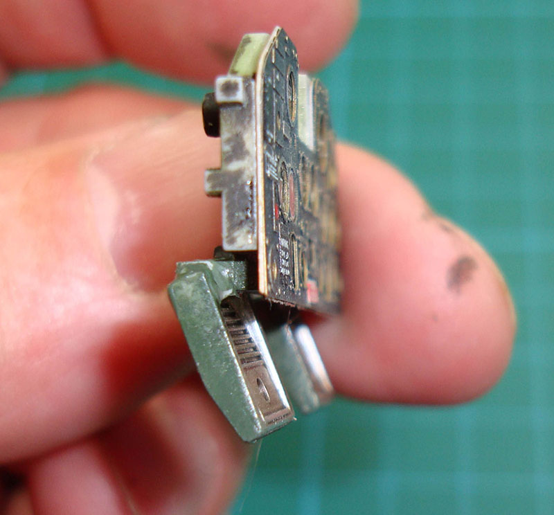
I've mounted the Airscale instrument panel to the kit backplate and then I looked at those rudder pedals. The kit would have you attach them to the bottom of the panel and hung down vertically. Hasegawa did the same thing with their 1/48 P-39 and the solution is the same. I added some Evergreen styrene to the back of the panel and mounted the rudder pedals further behind the panel and sloped them forward. In the real aircraft, the pedals would be further behind the panel, but this provides the illusion of depth when observed from outside the cockpit. Note: The instructions have you mount the gunsight to the panel. DON'T DO IT! It needs to mount higher into the windscreen and we'll look at that soon.
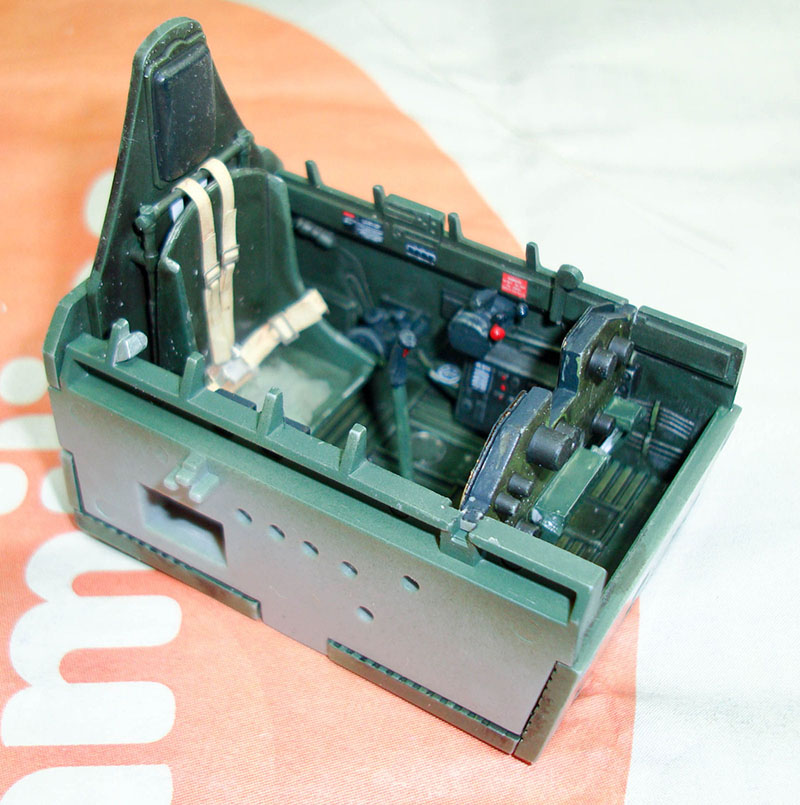
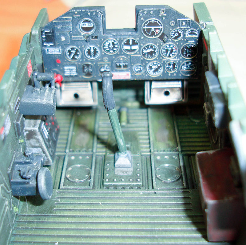
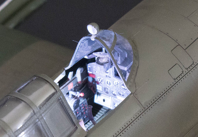
Here's the cockpit tub almost finished. The construction, painting and weathering is finished, but now it is time to install the white and red cockpit lighting. We'll be adding blinking navigation lights and cockpit spot lights using the MRC Light Genie.
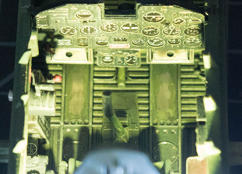
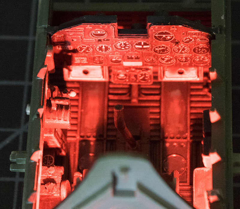
Here are two shots of the cockpit using the white and red LEDs now installed in the cockpit. The white LED is the 'cool white' (bluish) type and these old aircraft used incandescent bulbs which would be 'warm white'. I tried a dab of Tamiya clear yellow on the white lenses and you can see I got a greenish-white instead (let's see, blue + yellow = what again?) I'll use the stock white LEDs instead. The red LEDs look great.
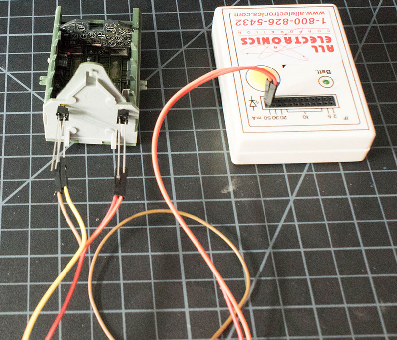
This LED test unit is 9 volts and provides the resistance to test 3 volt LEDs. Here's a quick LED tutorial as well as a look at the Light Genie in action which will be used to provide remote lighting control of this build. With the cockpit completed it is time to focus on the engine.
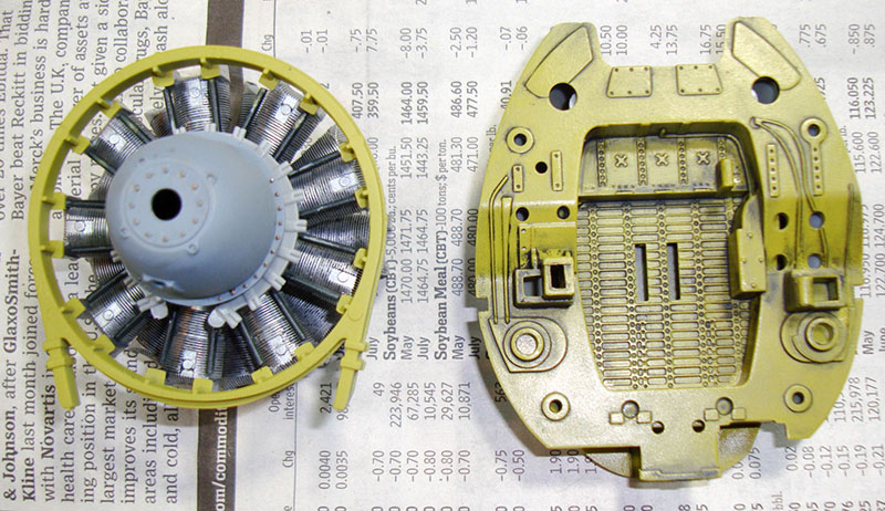
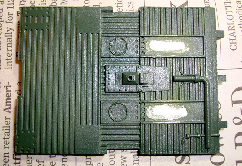
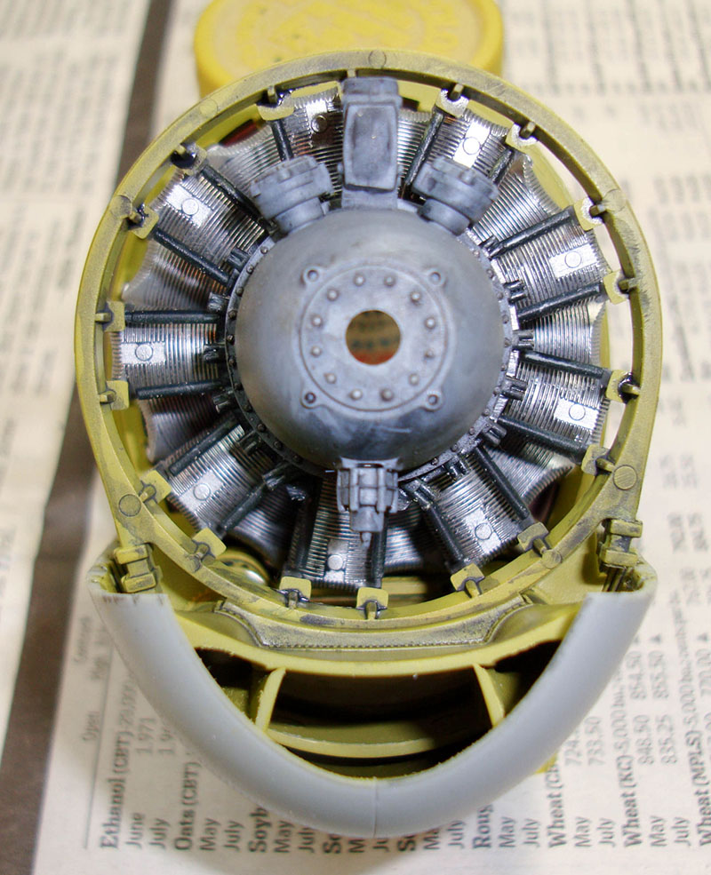
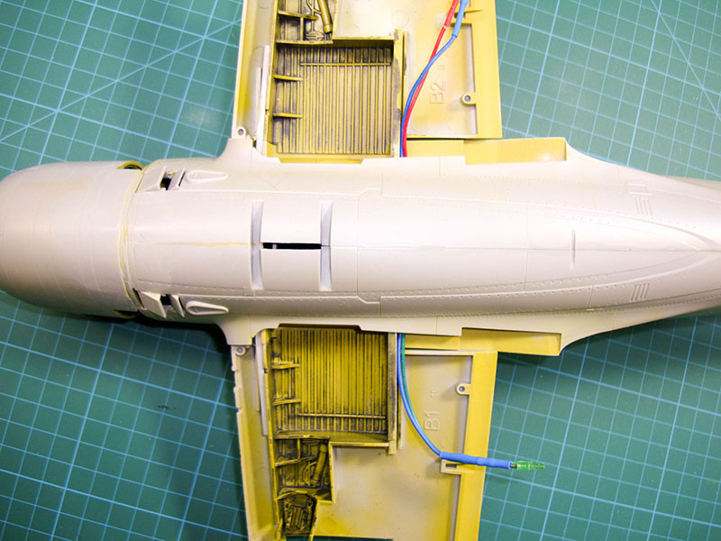
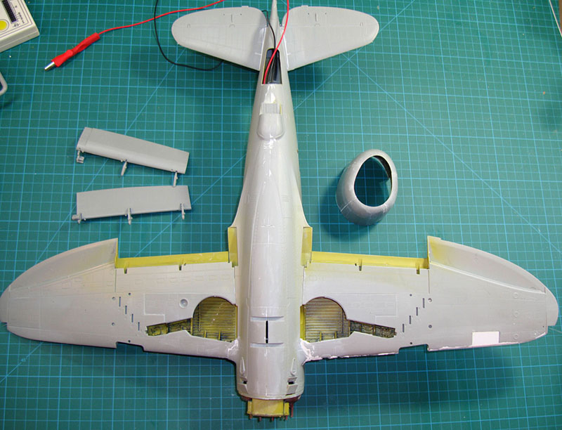
It was time to spray the model's visible interior parts in chromate. I've seen P-47s in chromate green and in chromate yellow (sometimes both) so I opted for chromate yellow using Tamiya's Yellow Green. The paint went down fine, but something was needed to make the molded-in details pop. The solution was AK Interactive's gray panel line wash. This is great stuff as you can literally coat the parts in the stuff using a paint brush, let it dry, then wipe away the excess with no effort. I applied the wash over a coat of Future as washes and flat paints don't work well together. Now it looks like the engine enclosure of a radial engine with a little oil and grit in the recesses.
Here's the same treatment to the main wheel wells. The wash brings out lots of details and I will simply add additional colors where needed.
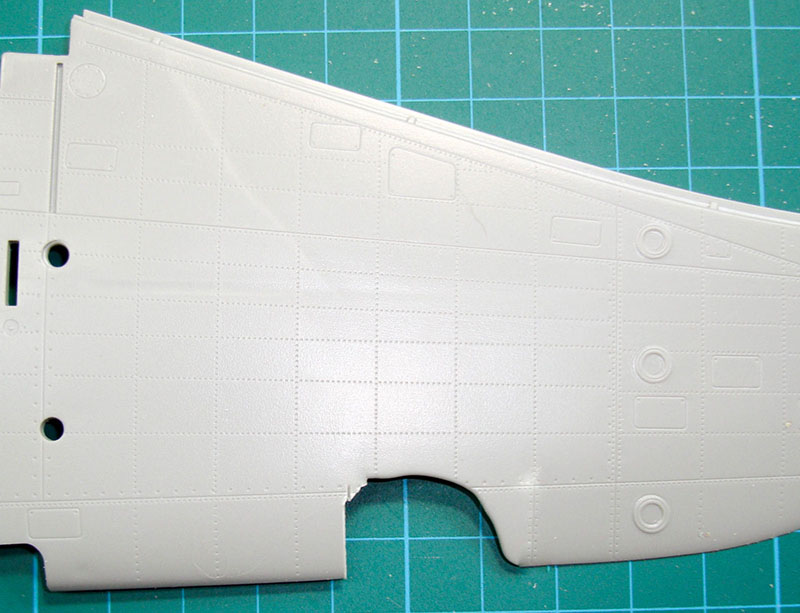
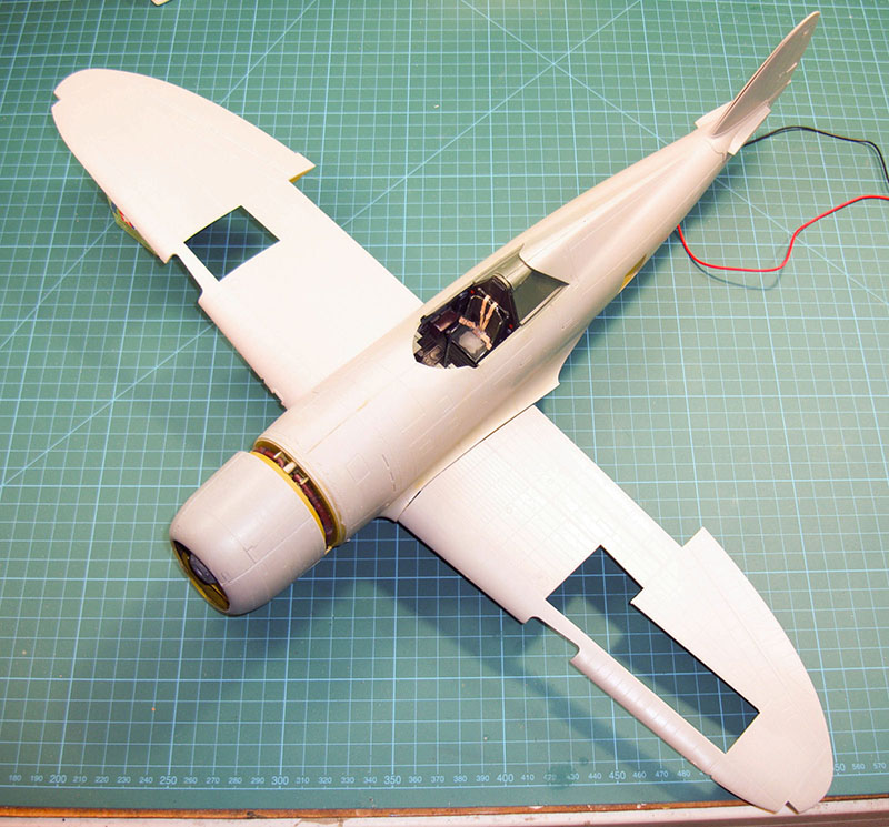
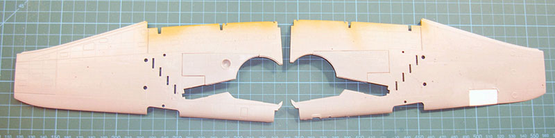
While I was working with the wheel wells, I decided to test-fit the wings. I don't know how I missed the short-shot wing, but this happens with injection molding. Kinetic's customer service is outstanding and while I have no doubt I can obtain a replacement part, I've already started squaring up the opening. When you see this next, we'll be repairing this with sheet styrene and moving on.
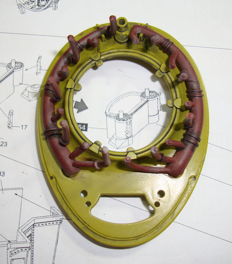
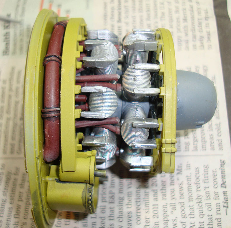
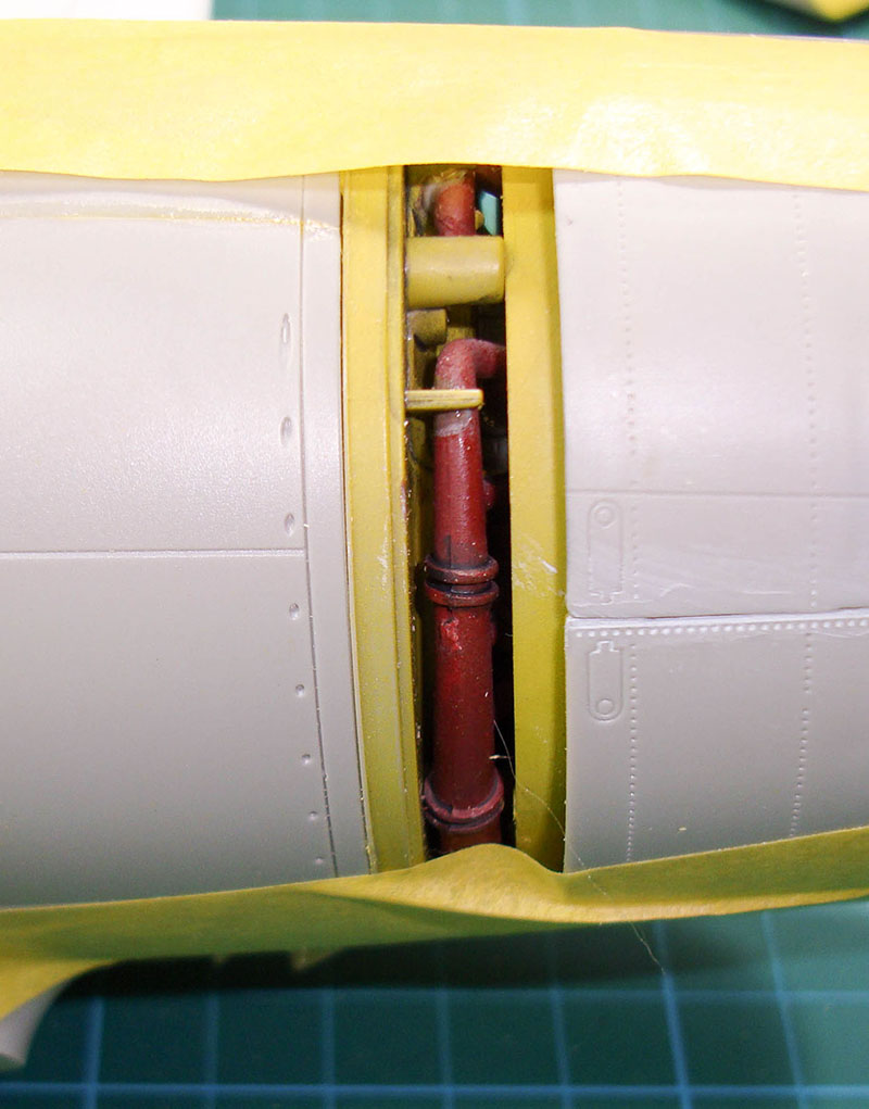
The major subassemblies start coming together with the engine and firewall. First, the collector ring is assembled and mounted to the firewall. The problem with this portion is that there are no positive locators to mount this other than one half-ring at the top of the firewall for each collector ring half. I opted to glue these down but in retrospect, I recommend leaving them loose until the engine is in place. I had completed the induction pipes which mount to one of the two holes in the rear of each cylinder and the exhaust pipes that are attached to the collector ring mount into the other holes. It took some patience and lots of fiddling to get everything lined up, but the instructions are quite vague here and you'll just have to experiment to get the assemblies together.
It was at this stage that I did another test fit because behind the engine block mounts the accessory pack and more ducting/plumbing that mount to the main firewall in front of the cockpit. The instructions have you assemble the entire engine assembly together and then mount that to the front of the assembled fuselage. The problem I saw was that the rearmost firewall is supposed to fit into a pair of mounts molded inside the fuselage halves and you don't have any way to see in there to mount them, much less glue them. That led me to consider mounting the rear-most firewall first, then mount the engine assembly onto that. When I test-fit the assembly above (without the accessory pack and rear-most firewall, it mounts directly to the front of the fuselage halves. What's more, nothing behind that front firewall is visible after assembly. So why am I messing with the rear of the engine? That's now deleted. This is a classic case of over-engineering and putting details where they'll never be seen again.
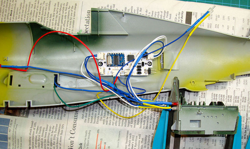
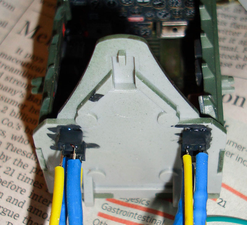
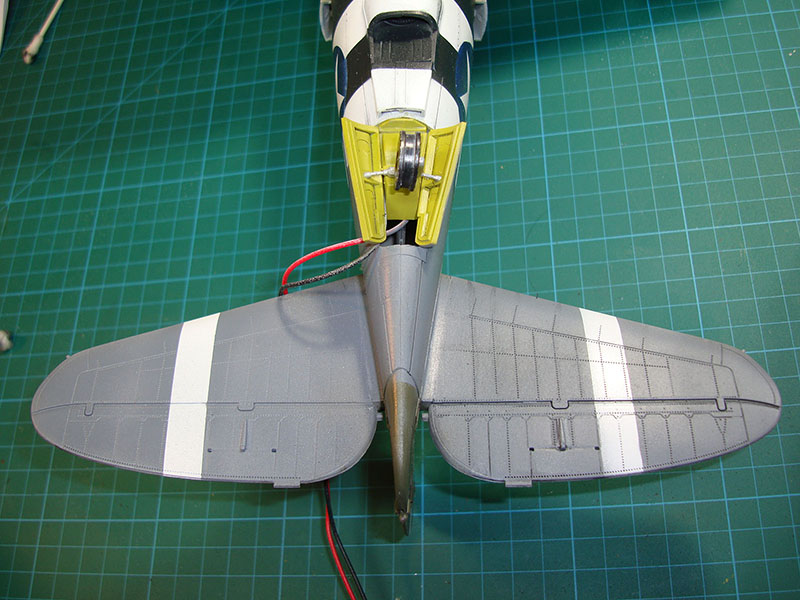
According to the instructions, the cockpit assembly and main spar assembly go into the right fuselage half first. I mounted the Light Genie to the fuselage half with Velcro, then permanently installed the red and white cockpit lights into the rear of the cockpit bulkhead. I painted the rear of the LEDs flat black to minimize the light that will shine inside the rear fuselage after assembly. Of course I powered up the system to make sure I haven't damaged the lighting system and all is well so far.
Before I can close up the fuselage halves, I need to run the wingtip lights out of the fuselage and fore this, I opted to cut a slot behind the rear main spar on each side for the wiring to pass into the wings. I've cut a corresponding slot into the wings as well. The last step before closing up is to mount the rear navigation light to the fuselage half and run a fiber optic line out to the rudder.
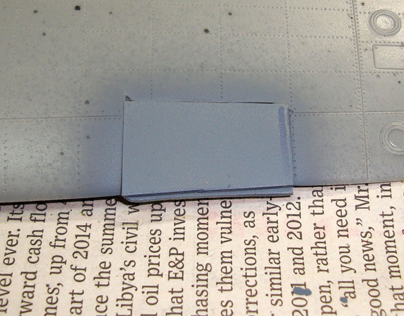

Remember that short-shot wing photo earlier? Here's that wing with some laminated sheet styrene fitted and glued into place. The lower sheet is wider so that I can file and sand the wing contour, especially the leading edge to match the surrounding kit wing. The primed photo (left) shows the patch from the exterior side while the unpainted photo to the right views from inside the wing half.
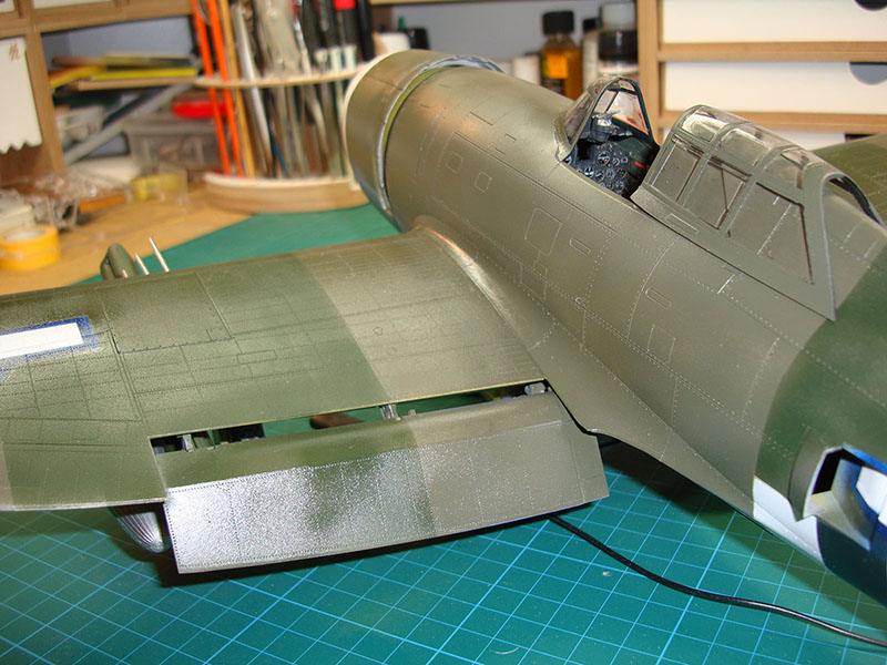
The magnetos, prop governor, and final engine details are in place with the lower cowling mounted. You can see in the image to the right that the only details you'll see with the cowling closed is that collector ring and even that would be invisible with the kit's closed cowl flaps. I'm replacing those with the beautiful resin open cowl flaps from Master Casters.
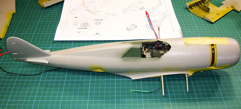
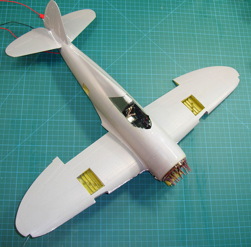
This is the result of a lengthy wrestling match. After running the red and green LEDs out of their respective fuselage channels and installing the fiber optic run for the rudder navigation light, I put the cockpit tub onto the wing spar mounts (not glued) and trapped everything inside the two fuselage halves. The wrestling part came about in trying to get the cockpit tub seated in both of the fuselage halves' mounts as well as on the main spar. I finally heard the gratifying 'snap' and I started gluing the fuselage halves together. I used a Touch'n'Flow to get Tamiya Extra Thin Cement onto the various mounts for the cockpit tub deep inside that fuselage. I used Tamiya tape to keep it all in shape while I went off seeking and adult beverage.
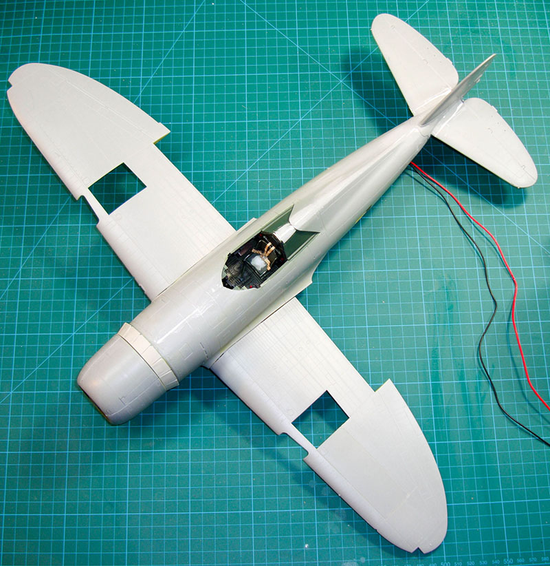
When I returned the next morning, everything had set up nicely and I have a little more gluing to wrap up (vertical stabilizer) and some touch-ups elsewhere. I also mounted the engine subassembly to the front of the fuselage and now the model is beginning to look like a Thunderbolt.
I still need to glue the rear cockpit bulkhead to the fuselage but you can see how good the fit of this kit looks.
Since I am running lights and fiber-optics in the wings, I can't assemble the wings per the instructions before attaching them to the fuselage. Instead, I glued each upper wing half into place and clamped the mainspars from the fuselage to the wing internal structure.
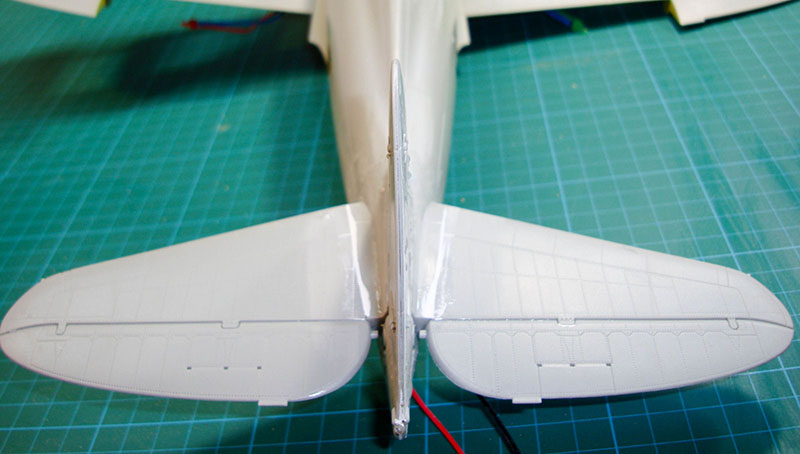
With a little fiddling, the wing/fuselage joint is close enough now to fill with some thin strip styrene. That will wait until the wings are fully assembled. Note that the vertical stabilizer isn't glued together yet - there is a slight warp in both halves that is easily rectified, but it will wait until the horizontal stabilizers are in place so I can square up the tail at that point.
Here's a look at the bottom halves of the wings with the various inserts glued into place. This is also where the instructions are a bit unhelpful as well. Ignoring the captions stating left wing assembly and the diagrams are for the right wing and vice versa, they don't call out the wheel well insert for the right wing (part 55) at all. By this time, you're already intimate with this kit as the instructions provide the part numbers needed for a given assembly, but no clue on which parts tree they're located.
The insert that goes into the left outboard section (part 76) fits snugly after some fitting and filing to thin the part to sit flush with the surrounding wing. The wheel well inserts also required thinning but now they're glued into place and only require a bit of Mr. Surfacer 500 to close those slight gaps.
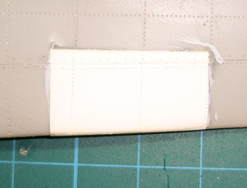
Speaking of inserts, I've also added the rivets and panel line to the short shot patch to blend it into the surroundings. One more coat of primer will tell if we're done here.
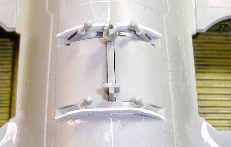
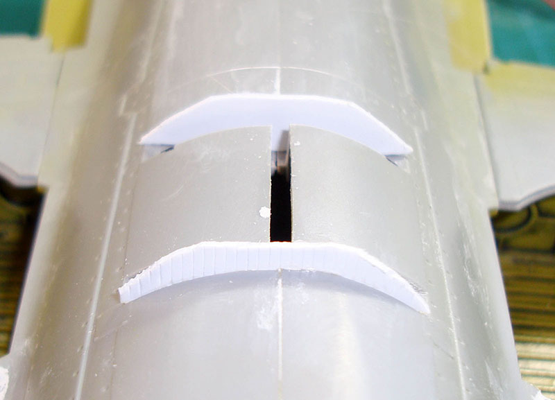
It was time to get the tail section together. I assembled the horizontal stabilizers per the instructions and then had to thin the tabs that insert into the fuselage so they'd fit. Note that the pushrod actuators for the elevator trim tabs are not visible here. They belong on the underside of the elevators but the instructions made it seem that they could be on either side. I wrapped up this effort by applying 3M Acryl-White Putty on various parts of the fuselage and doing a rough wet-sand.

While the putty was drying, I test-fit the resin cowl flaps from Master Casters after painting the inside aluminum.
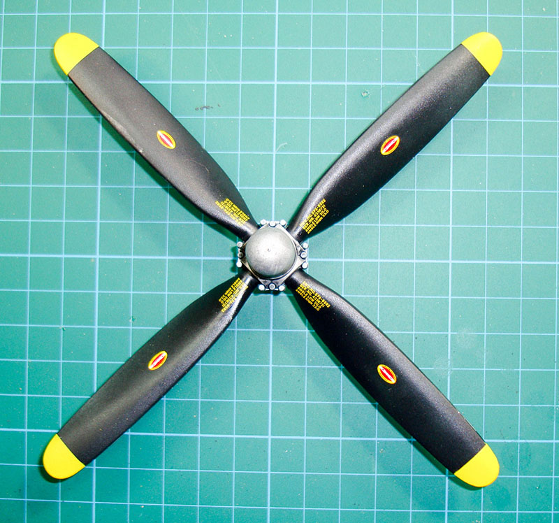
I decided to skip ahead to the propeller for a diversion. There are four propellers in this kit which shares many parts with the bubbletop Thunderbolt. The subject I'm building was equipped with the Hamilton Standard uncuffed propeller so I painted, weathered, clear-coated, decaled, and flat-coated the prop as you see it here.
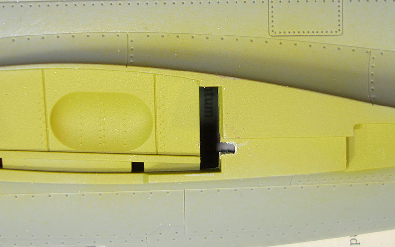
It is time to tackle the wingtip fiber optics. I need a path into the wingtip lens which I drilled out with a pin vise.
The navigation LED in each wing was tacked into place with an UHU clay-like reusable adhesive. The fiber-optics were inserted into a small-diameter section of heat-shrink tubing and white glue was used to fix them in place. When they had dried, the next size of heat-shrink tubing just happened to fit snugly over the LED. Again I used white glue to mount the tubing onto the LED and inserted the smaller tubing with the fiber optics and white glued that against the LED. The white glue dries clear and neither harms nor interferes with the LED or fiber optics. The other end of the fiber optics was passed through the hole in the wingtip nav light and white glued into position.
Once the white glue had dried, I powered up the Light Genie and had flashing nav lights visible on all three fiber optic runs. It was time to close up the wings. Even though I'm modeling this kit with the gun doors closed, I installed the gun trays in the wings to help align the gun barrels as well as provide structural strength to the outer section of the wings. I mounted both to the lower wing halves per the instructions, then test-fit the lower wings. The gun tray in the right wing was obstructing the fit of the wing so I removed it from the lower wing and glued it to the upper wing half instead. That worked. With the wings fitted, I glued the halves together, and then applied the first round of the Acryl-White Putty.
The flaps were assembled per the instructions and it looked like they were supposed to be installed before the wing halves were assembled, but after test-fitting these, they'll install later just fine. I'll add these when I'm done painting the airframe.
You'll also note that the engine is off the aircraft again. I had been thinking about what I'd do different if I build this again and one item would be to get that firewall blending to the front of the fuselage without the engine. So while I was handling the model, there was a snap and now I have my wish. I won't be reinstalling the engine and cowling until after painting this time.
Now to address that huge 'H' molded into the underside of the fuselage between the wheel wells. These are three slots which are supposed to hold the centerline fuel tank suspension system, but the three parts that make up that system are not large enough to use up that space. I used some sheet styrene out of an Evergreen odds and ends pack (Set 9002) and cut rough shapes to fit with the kit parts and close up the gaps. The photo on the left shows the white styrene pieces dry-fit with the kit suspension system and now the fit is snug. With the kit parts removed (right photo) I glued the styrene pieces into place.


When the glue had dried, I blending the white styrene to the fuselage contours (left) and then dry-fit the suspension system (right) to double check the fit. Any left-over gaps will be addressed with Mr. Surfacer.
Speaking of Mr. Surfacer, my ten-year-old jar of Mr. Surfacer 500 finally became unusable and when I tried to find another bottle (or two), I also discovered that the product isn't readily available in the US. While I'm using 3M Acryl-White putty for the more serious body work on this model, I like to use Mr. Surfacer for the little touch-ups that are required. I found a source through eBay for Mr. Surfacer from a hobby shop in Japan and after a week or so, my supply of Mr. Surfacer has been replenished.
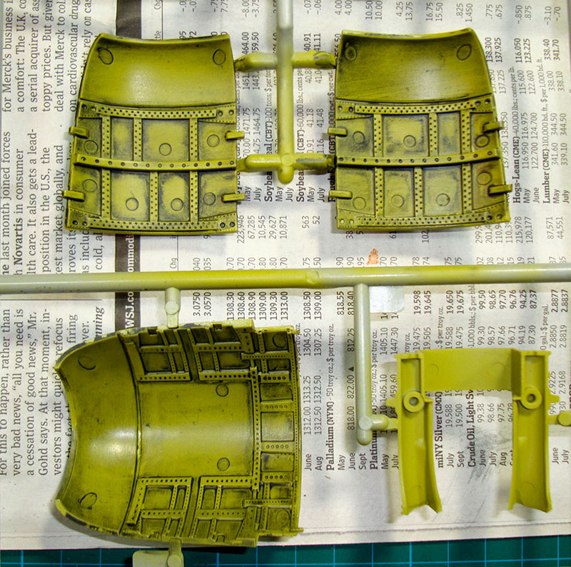
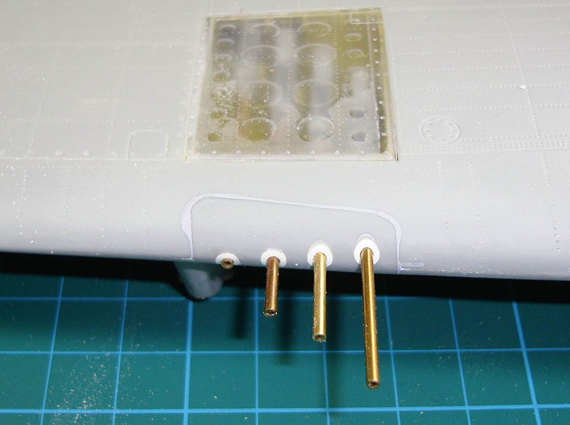
Now we're wrapping up the final details before heading to the paint booth. The leading edge inserts for the guns are now installed and blended (that to the Mr. Surfacer) and I filled the slight gaps in the wing/fuselage joint with strips of Evergreen styrene.
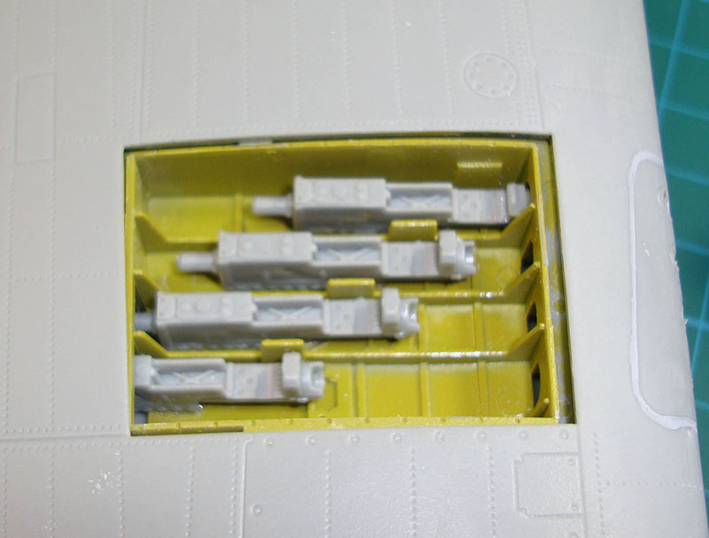
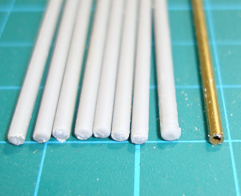
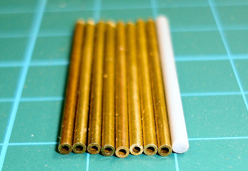
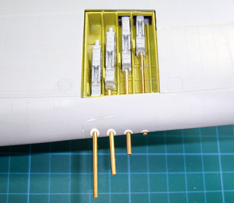
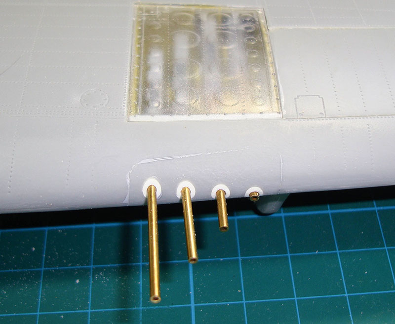
I was tempted to simply close up the gun bays and worry about the gun barrels later and I am very happy I didn't. I installed the guns in the wing bays but I didn't bother to paint them since they were going to be closed up. I also removed the eight 'barrels' from the parts trees and discovered quickly how little I thought of them. In 1/32 scale, hollow .50 caliber gun barrels are noticeable so at 1/24 scale, they are a necessity. That's when I poked through the K&S Tube Assortment I always keep on the bench for such contingencies. Sure enough, their 1.5mm diameter tubing is nearly identical in diameter to the kit 'barrels'.
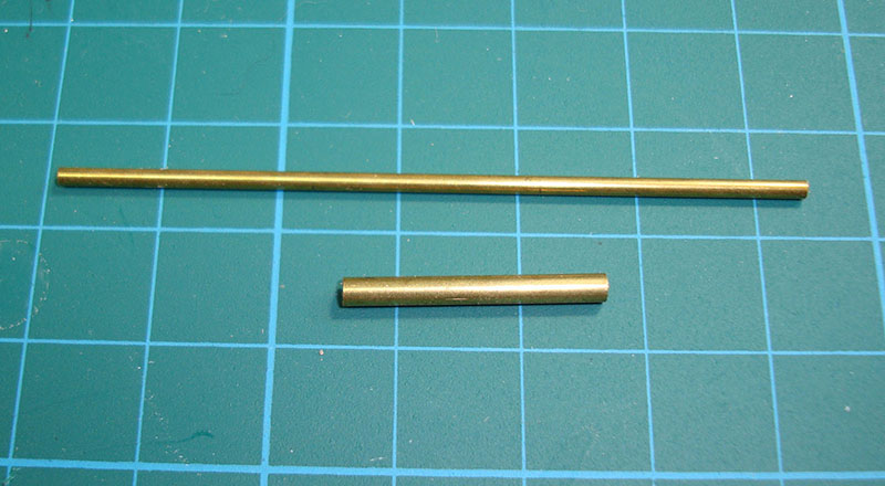

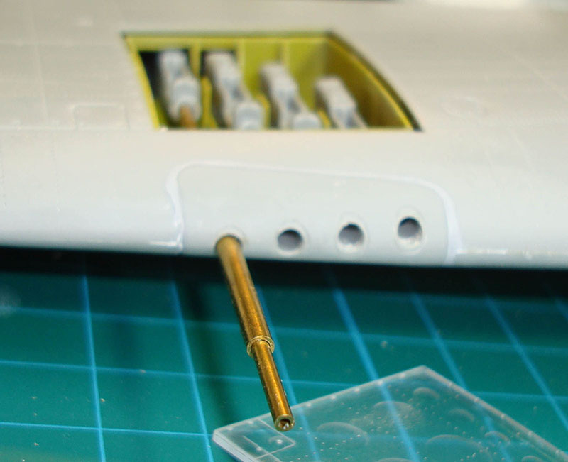
When I inserted the kit barrels and my brass barrel stock into the wings, they sat at the bottom of a larger hole in the wing leading edge. While the sit in the mounts at the front of the guns, there is nothing to keep them in alignment through the wing leading edge. Looking at photos of the full-scale P-47, the openings in the wing leading edges are only slightly larger than the diameter of those gun barrels. At 1/24 scale, that opening would be virtually invisible, so I needed to close up those holes. My first thought was using K&S tubing the next size up and you can see in the images that they nearly fit nicely. The problem was going to be the metalwork needed to blend the larger diameter tubing to the contour of the wing leading edge. No bueno.
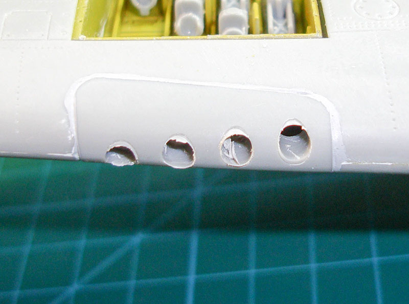
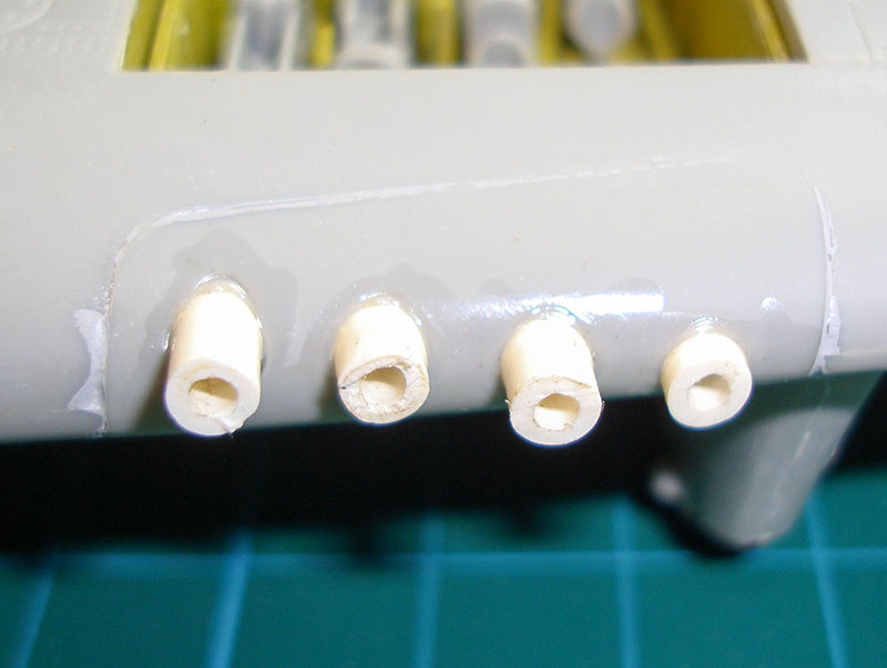

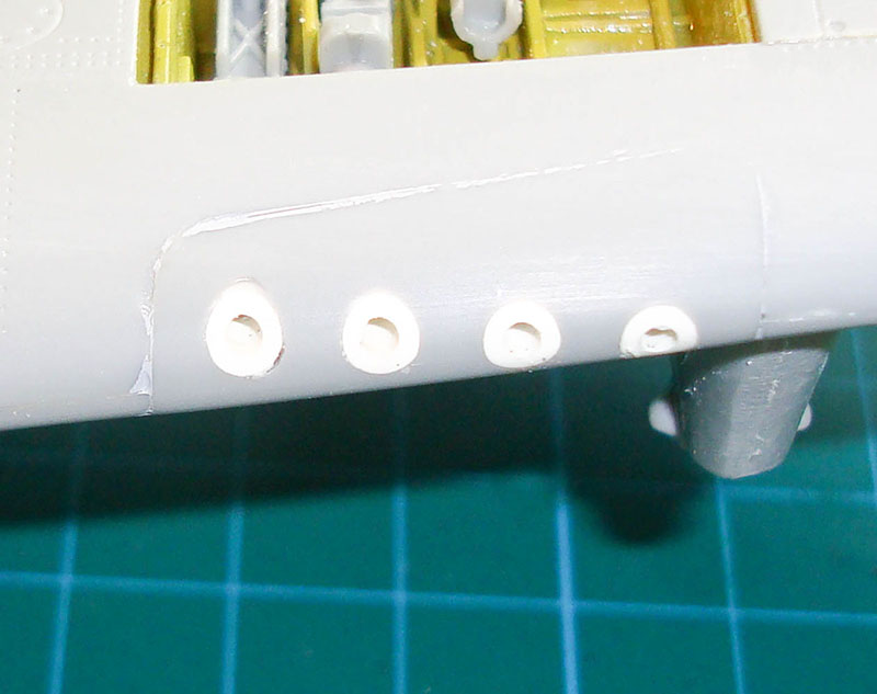
I rummaged through my stockpile of Evergreen/Plastruct plastic stock and found tubing that had an inside diameter of 1.5mm, but the outside diameter was larger than the wing leading edge holes. I used a drill bit to open up those holes, then I inserted each piece of plastic tubing into the wing leading edge using the brass barrel to align the tubing with the gun breech. When all was well, I applied liquid cement, let the wings set, then filed the tubing down to conform with the wing leading edges. I applied Mr. Surfacer around the tubing to address any issues left from the improvised bodywork.
I cut eight barrels to length and then used my Dremel tool to grind the tips that will insert into the wing leading edges into almost a point.
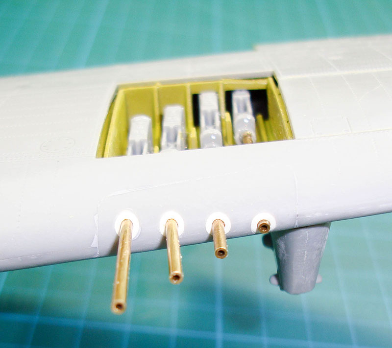
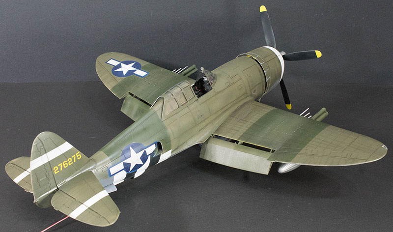
Here are the gun barrels installed in the left wing bay and there will be some barrel alignment (boresighting) done at the final stages, but the hard part is finished.
I dry-fit the clear gun cover doors and there were a few spots that needed to be trimmed to allow the doors to sit flush with the wing surfaces. Once they were flush, the doors were cemented closed and it is off to the paint rack.
Before I can apply the base colors for the P-47, I've got to plan the color layers that will precede them. First will be gloss white for the national markings and invasion stripes background, then using paint masks and masking tape, gloss blue for the next layer of national markings and gloss black for the invasion stripes. I'll also use aluminum metalizer in a few spots that will be show through some worn paint.
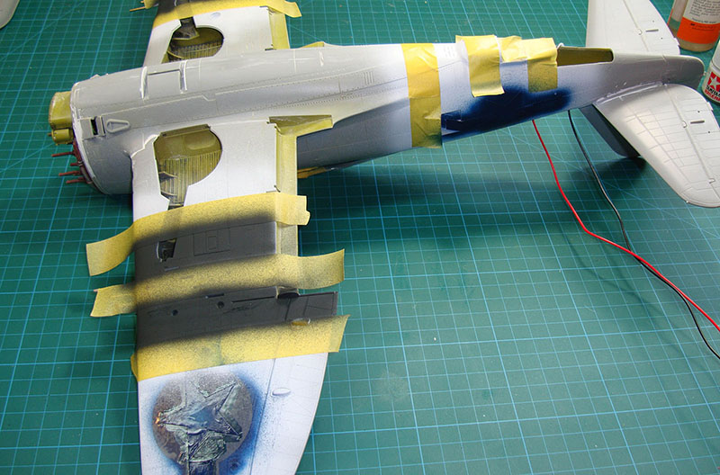
Here is a look at the model with the third color going down. The white had been applied, then the star and bar paint masks and invasion stripe masks laid down. Next was blue for the national markings and those masks were applied and liquid mask used to seal off the gaps between the two masks. Now the black stripes have been applied (photo) and these have been masked to prepare for the OD Green over Medium Gray paint scheme.
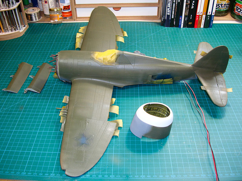
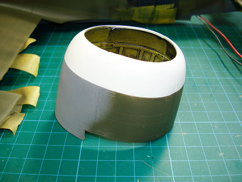
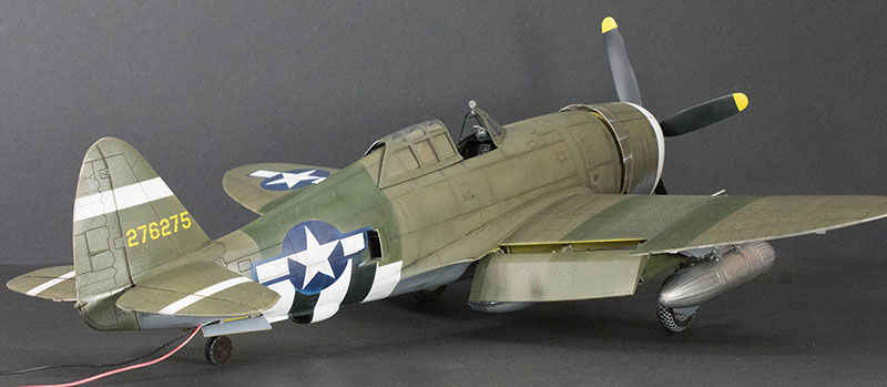
It is interesting to paint a model that has enough surface area to almost qualify for its own zip code. The base colors are now applied (OD Green over Medium Gray) and then it will be time to see how my first attempt at paint stencils worked out. I couldn't wait to see how the cowling looked.

Masking off and touch-ups started. The first color was Tamiya Flat White and I had covered virtually all of the underside of the aircraft. I later painted the area for the ID stripes on the horizontal and vertical stabilizers the Flat White as well. After I added the national marking masks for the white areas, I didn't apply as much coverage with the blue background so now I have some touching-up there that has started. The invasion stripes turned out nice. The aircraft is starting to look pretty nice and I haven't added any decals yet.
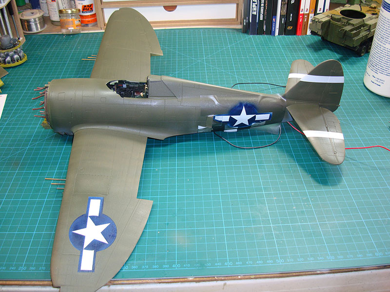


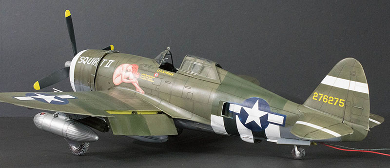
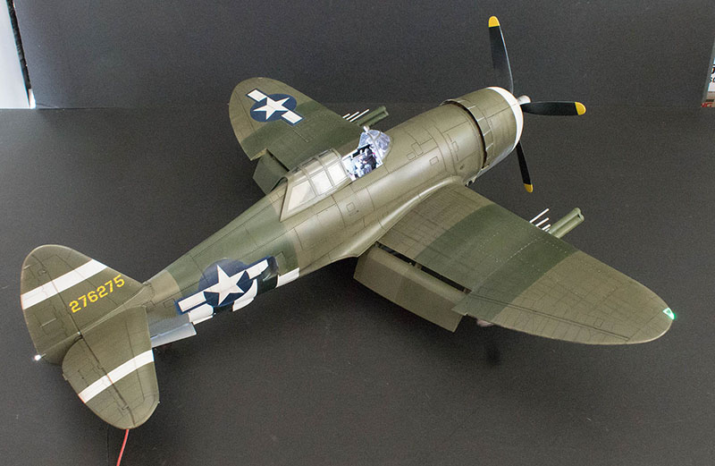
Touch-ups are completed and the model has reached that critical milestone - it is on it's landing gear! I've also added the second green over the upper surfaces that would have covered over the upper invasion stripes. Notice how odd-looking the color appears out of the bottle, but it darkens nicely when the Future gloss coat is applied below.
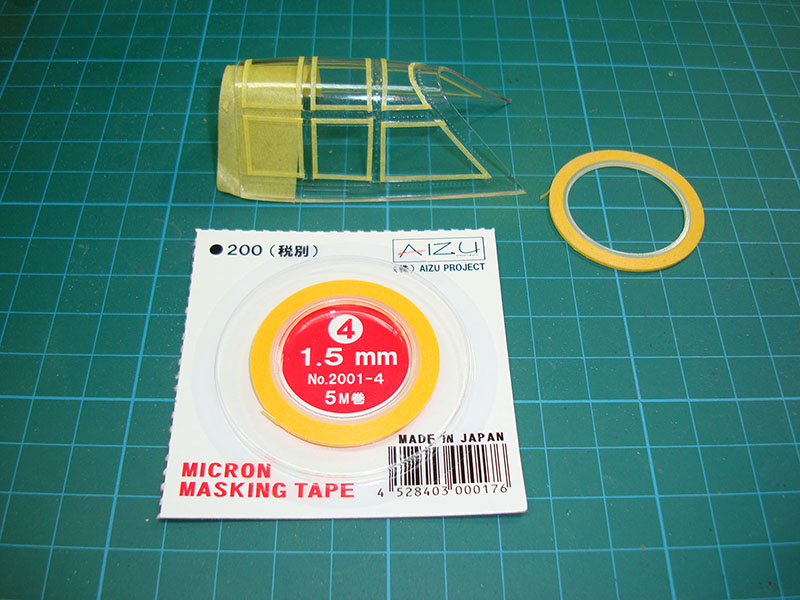
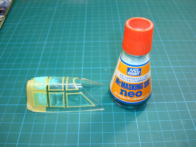
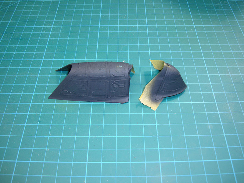
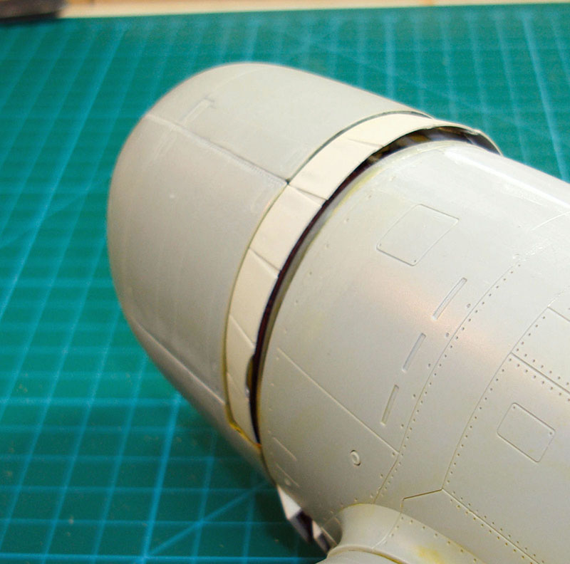
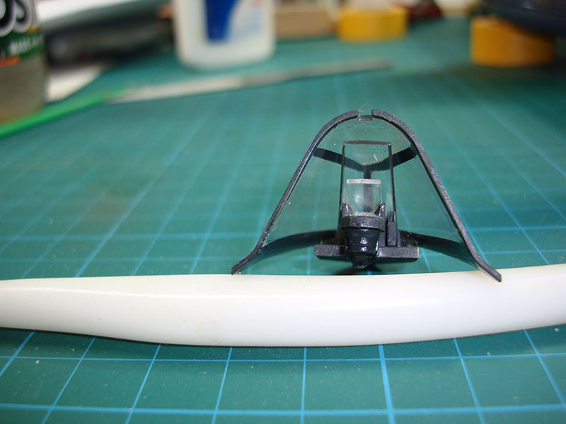
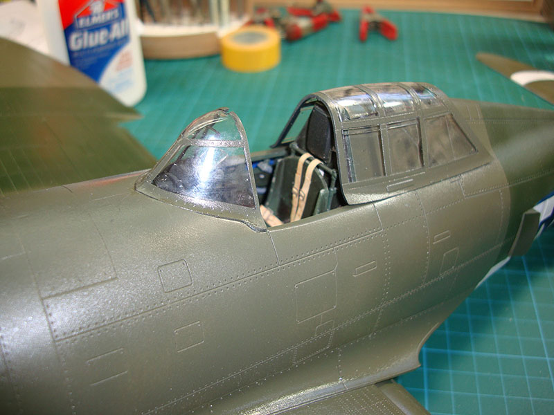
The next milestone is one I had been dreading - masking the canopy and windscreen. I had discovered that there were no paint masks available for this kit but I had recently acquired the Aizu Micron Masking Tape in different sizes and this looked like a nice opportunity to try the tape out. I applied lengths of the 1.5mm tape to the canopy, then used a cutting tool to carefully cut the tape at the frame intersections. It took a little time to develop the technique, but soon I had the clear sections of the canopy framed and I did the same for the windscreen. The next step was to apply a liquid masking solution inside the taped frames, in this case I tried Mr. Hobby's Neo which worked as any other available masking solution would. Once the masking solution had dried, I applied the inside color first, in this case Tamiya NATO Black. This was followed by Tamiya Neutral Gray to keep the final color from being too dark. The final color of course was Olive Drab 41.
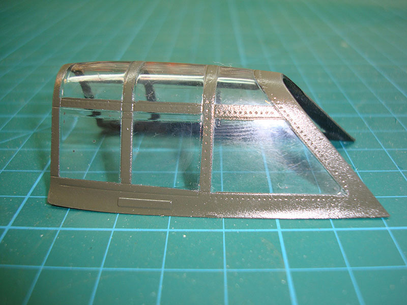
You can see how sharp those frame lines are once the masking was removed. You do need to be careful as the canopy and windscreen parts are quite thin so they may crack easily, fortunately mine held up.
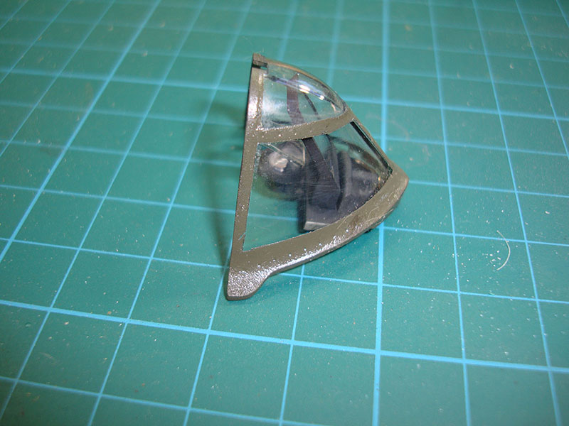
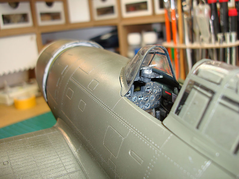
Before I can install the windscreen, I need to address the gun sight and armored glass that go inside the windscreen. According to the instructions, the gun sight mounted to the instrument panel but that was going to be too low. The plate that mounts over the instrument panel in Step 4 that holds the armored glass was going to be in the way of masking, so I deferred that step until now.
I assembled and painted parts Z16 and Y5, the armored glass and base plate (respectively) and the only parts in the instructions that tell you on which parts trees these can be found. When I test-fit this assembly onto the molded-on mounts above the instrument panel, there was no definitive location there. I decided to dry-fit the windscreen to see if that would help locate the proper position for Z16/Y5 and that's when I discovered that the pin located at the bottom-front of the windscreen was intended to plug into the hole at the front of Y5. I glued Y5 to the windscreen. When I test-fitted the assembly to the model, it no longer fit - the molded-on mounts obstructed the assembly. These mounts were snipped away and now the windscreen assembly fits nicely.
The last item on that list is the gun sight. Going back to Step 1, I assembled parts 9 and 11 thinking it was part of the gun sight but the instructions don't tell you where this assembly goes. Next to it is the gun sight itself, but while the instructions identify the base module (part 110) and the combiner glass (part 7), it doesn't provide parts numbers for the projector (part 135) and its lens (part 3). After finishing that detective work, I assembled and painted the gun sight and mounted it to the Y5 base plate so that it sits in proper position.
The windscreen and canopy are dry-fitted in place before the windscreen is cemented into place. Even after all of the test fitting, there was still a slight gap between the windscreen and fuselage.
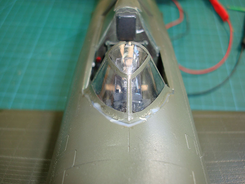
Rather than using filler and having to sand and repaint the windscreen, I used an old cheat and applied white glue to the gap which dries clear and takes on the surrounding color.
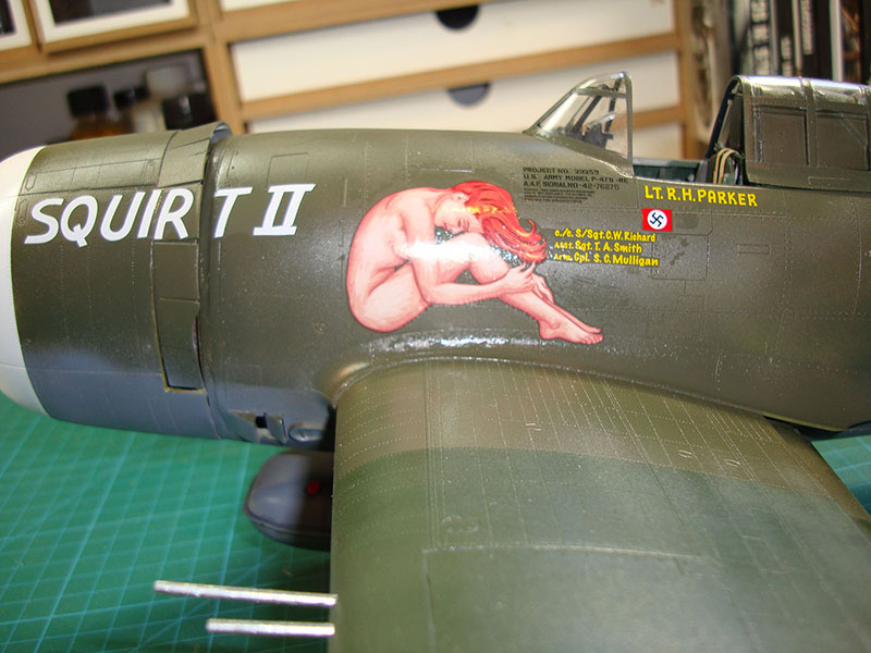
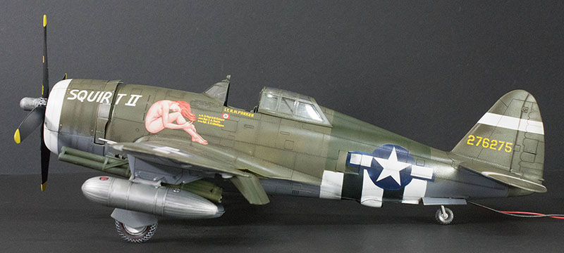
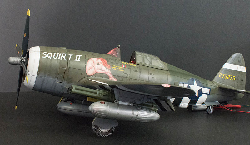
Since I opted to use paint masks for the national markings and simple strips of Tamiya tape for the invasion stripes, these were the only decals that needed to be applied (as well as the tail numbers). These decals are straight out of the box and go down very nicely.
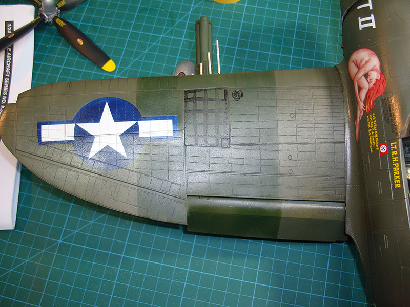
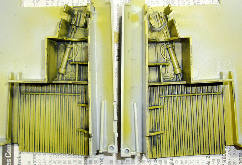
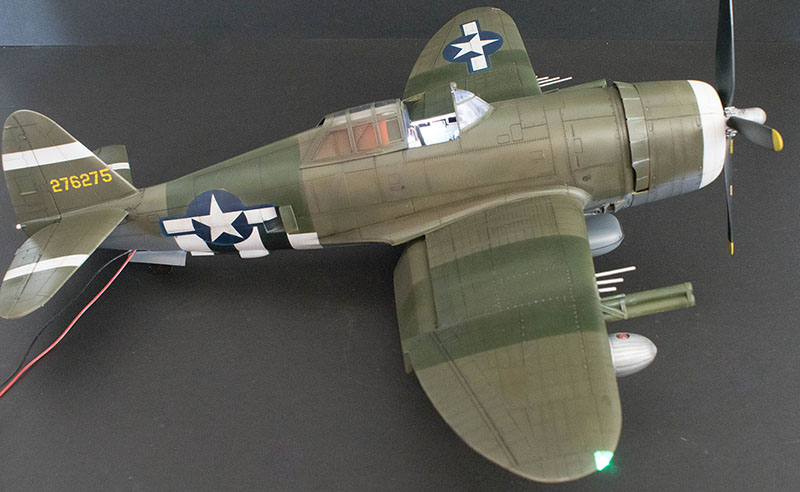
Now begins the process of weathering the model. I don't believe in heavy weathering as I've seen on some builds because the result appears (to me) to make the aircraft more like scrap metal than weather-worn. This is an art form, so to each their own. Here I am applying AK Interactive's panel line washes using a paint brush to apply along panel lines and lines of rivets. Aside from the gun door on the left wing, the rest of the wing is already weathered. Simply apply the wash, let it dry, then wipe away what you don't want. The results highlight the molded-in surface details and alter the paint shading slightly as if I had pre-shaded the model (which I no longer need to do with this stuff).
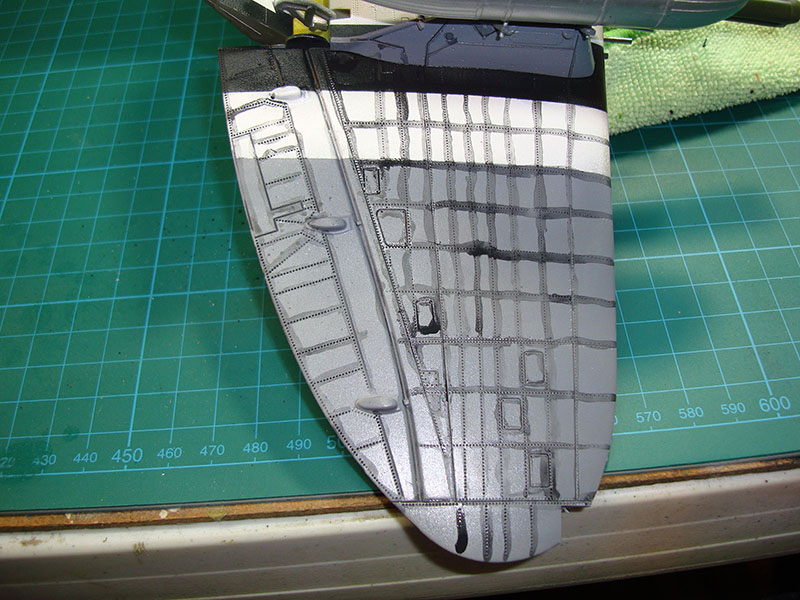

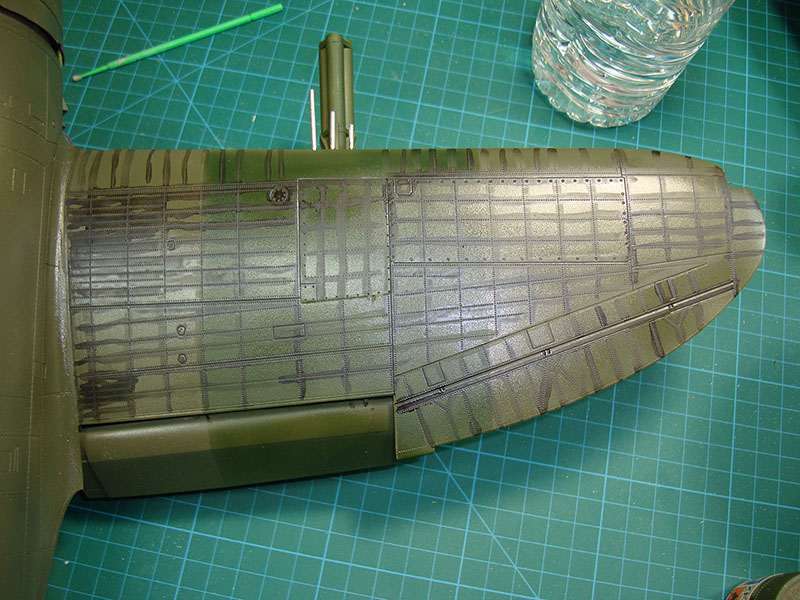
Here's a look at the lower left wing before weathering, during, and after the excess has been wiped away.
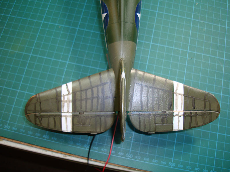
Here's another example with the undersides of the horizontal stabilizers before and after the panel line wash. I used a few other washes and techniques to add some age to the aircraft and I am rather pleased with the results.


It was time to see if the MRC Light Genie was still operable after the wet sanding and other not-so-friendly environmental exposures. The cockpit lighting works great! The navigation lights also work.

This was a fun project despite the glitches in the instructions. It took longer to complete than I had planned, but I had the opportunity to use this project to try out a variety of tools and techniques. All I can suggest with this project or any other for that matter is to test-fit everything so you can understand what the instructions intend, even if they're not clear.
© Michael Benolkin 2016
This article was published on Wednesday, July 20 2016; Last modified on Sunday, February 03 2019