
1/32 Rockwell OV-10D Bronco
By Jack Gryskiewicz
The model started as a vacuform “try-out”/first effort made by Lee White, who built it up until a basic center fuselage pod plus two tailbooms, including the main wing. He didn’t fancy the effort finishing the model anymore at a certain stage and sold it to Larry Hawkins, who in turn sold it to me, untouched. I had my eyes on this model for quite some time, and being thrilled by the idea of finishing this project and learning and improving some scratchbuilding techniques along the way, got me started planning and searching information and detailed pictures on the Bronco.
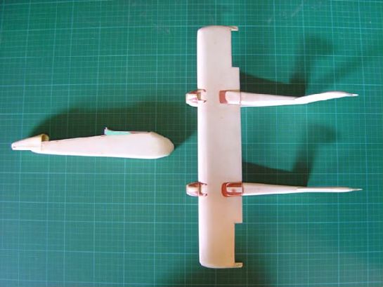
In general I had to figure out how to continue what Lee had started, since he indicated he encountered problems with the nosewheel bay, which collapsed on him and he was a bit in doubt on dimensions in general.
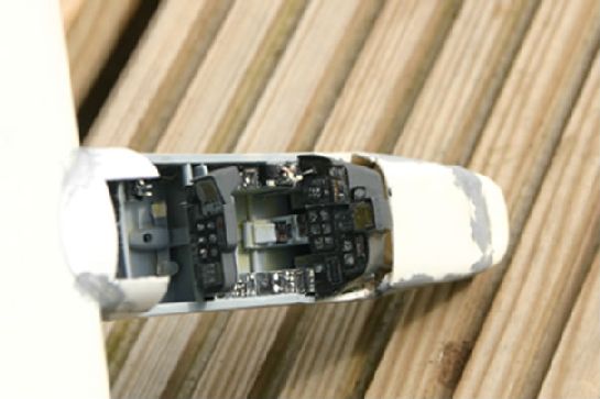
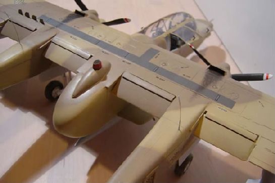
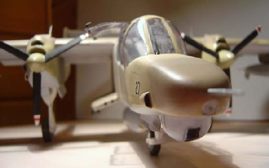
As it turned out after checking several photos and line drawings, the shape of the “D” nose was incorrect, but I could live with certain “inaccurate” dimensions, placing the model in the 1/32-1/35 range, because when overlooking all the various figures (wingspan, pod dimensions, etc) it would have been indeed a dead project in changing these items, since in overall look and calculations the nose was only 1/6 inch too long and both tailbooms also were 1/6 inch too far away from the center pod,but in all having more 1/32 figures than 1/35.
Concerning the nose shape, I had to cut it along the horizontal plane, and by doing so opening a lid so to speak, and adjust it in such a way that when refitted again the nose would have a lower profile and less steep angle from the tip of the nose towards the windshield. Also by opening the nose I could try to adjust the nosewheel bay (which didn’t work, so I just left it the way it was, it wasn’t that terrible after all) and fill it up with lead weight, since this model would definitely be a tail-sitter without some counter weight in the nose…..
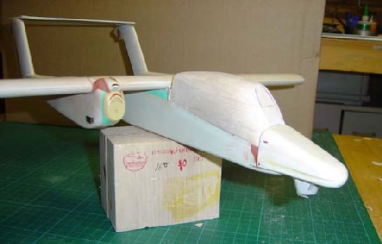
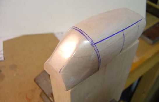
Note the off-sized nose in the picture above with the balsa mould intended for the heat-formed canopy lateron.
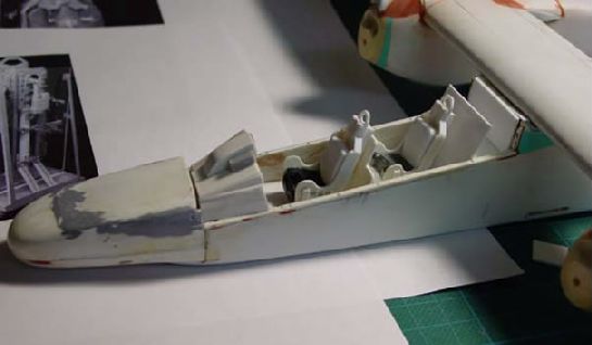
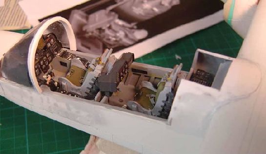
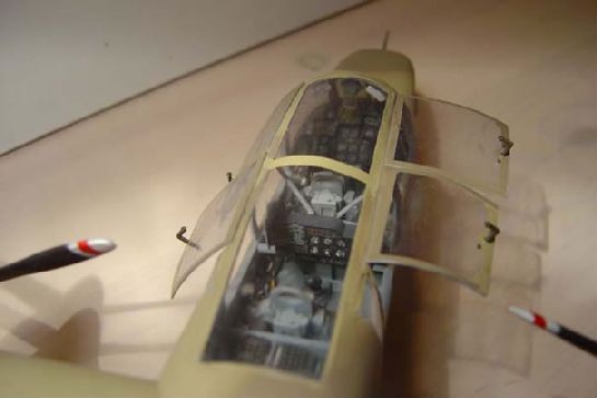
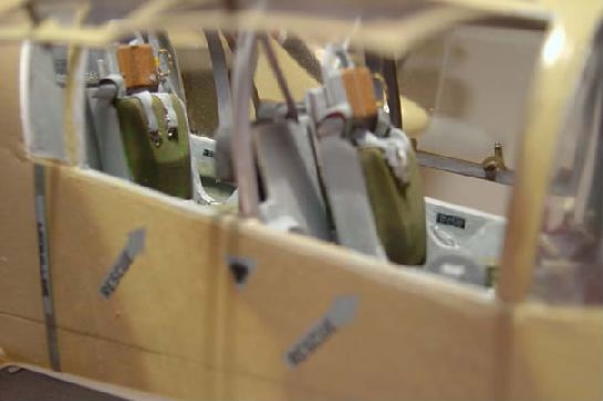
Using mainly Squadron signal publ. 154, dealing with the Bronco in action, together with what I could come up with researching other documentation, but finding the internet very, very usefull in gathering fairly good pictures on the interior, I started scratchbuilding the spacious interior, building up the instrument shroud, constructing instrument panels, both front, rear and side panels, ejector seats, radio shacks behind the second seat, etc, etc. Suffice it to say that the Waldron punch & die set and several Reheat Models products were invaluable at this stage.
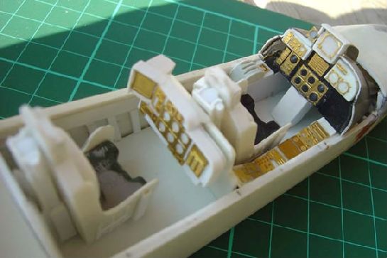
I used the Injection Site to get some detailed info and pictures on the Bronco’s NAA/Rockwell LW-3B “bang-seats”.
As shown I constructed a balsa mold in order to heat-form the windshield shape and get a feeling on how to build the rest of the “greenhouse” outfit.
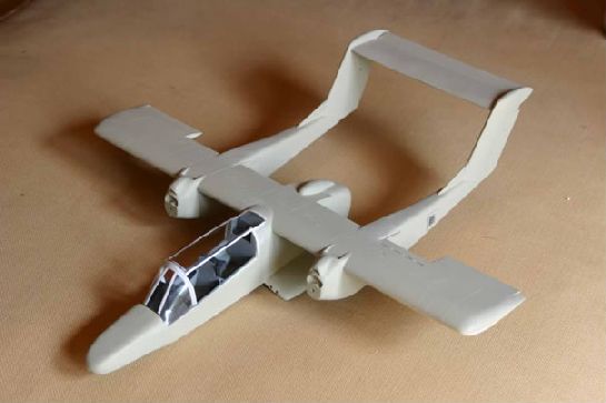
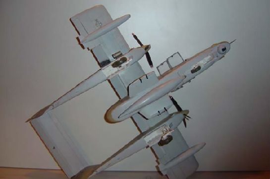
Before I could go on building up this section I had to attach the main wing section, together with the tail booms to the fuselage pod, because I had to blend in the part behind the second seat with heat-formed shaped plastic between the wing section and the fuselage pod. Also I had to blend in the windshield section to the nose by means of lots of filler (bondo) and stuff. After this would be ready I could “fill in” the remaining clear sections.
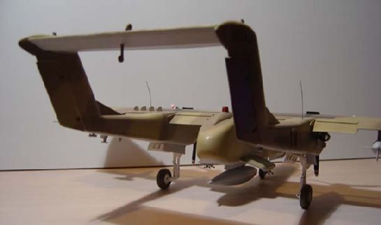
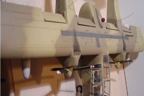
But before I ventured into this terrain, and before attaching the wing to the pod, I got to work on the wing itself, creating the four flaps in a drooped position, constructing the ailerons and scribing all the necessary panel lines. Also making up the spoilers on top of the wing (only on one side in the open position) which in reality aid in a tight turning capability because they are linked with the aileron movements, creating more drag on the lower wing.
The flaps are of the double slotted type, creating a gap between upper and lower wing parts, by means of a hinged part (on the flap itself) coming down below the wing and the slotted part on the topside of the flap over the wing when travelling downwards. These aircraft had tremendous short takeoff and landing capabilities.
This shows the aft and front part of the “blend-job”.
Again, after the wing was attached to the pod, I could construct the bulge on top of the rear of the fuselage pod at which the infrared jammer was attached. Also the side sponsons were scratched and attached to the underside immediately below the wing section.
I constructed two chaff/flare dispenser boxes and filled them with fine hollow tubing, cut out the appropriate spacing in the tail booms and glued the boxes into them.
Next I had to construct the rudders with convincing linkage openings to the vertical tail surfaces, and the horizontal plane between the booms with separate elevator, placed in the up position. The rudders were placed slightly offset as well. During all the constructing, I scribed several “skin” parts accordingly.
The frontal sides of the engine cowling had to be readjusted slightly to have a better appearance, and after this was done, a first primer coating could be sprayed on.
Now I could continue finishing the “greenhouse” construction, making the framework with evergreen styrene strips, and the separate window paneling by heat-forming over the balsa mold. Of course through the various constructions i had to do some painting too, and eventually the cockpit was finished; seats, belts, buckles and all.
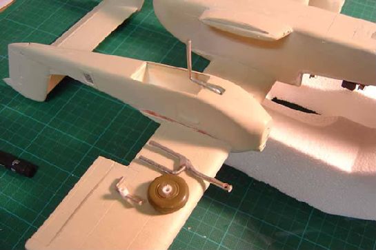
Turning to the underside I built up the insides of each main gear wheel bay and started scratching the gear doors both front and main bays. The main gear itself was constructed from metal rods and finally superglued and epoxied together. Main wheels came from some old Revell F-4 kit
Nose gear came from several parts out of the parts box, as well as the nosewheel (can’t recall its origin). Linkage parts also came from the Reheat stash.
Pylon tanks and centerline tank were made up out of adjusted parts in the parts box, as well as the spinners with counter rotating prop pitch. Props were made from “re-adjusted” old P51A Revell propellors.
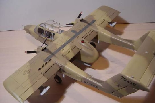
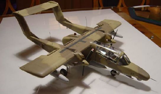
I wanted to make it a “first gulf war” aircraft, so I used the guidance material in the squadron publication together (again) with website information. I was a bit apprehensive at the outcome of my paintjob, still not having enough confidence/experience I guess, but after spraying the camo on top and the grey undersides (using the Kuwaite A4 camo colors scaled down with percentages of white) it turned out to my likings.
Final touches were several antennae, horn balances on the horizontal tail and static dischargers on main wing and vertical tails, several airscoops (attached of course before paint spraying), position- and navigation lights, pitot tube up front and ordnance racks on the sponsons and of course the under nose FLIR turret.
© Jack Gryskiewicz
This article was published on Wednesday, July 20 2011; Last modified on Saturday, May 14 2016