
Kitty Hawk 1/32 OV-10D “Bronco” - Part 2: Wings Wells & Booms
By Brian Leitch
Kitty Hawk OV-10D “Bronco”
Scale: 1/32nd
Manufacturer: Kitty Hawk Models
Accessory/kit #: 32003
Kit type: IM Styrene + PE
Part 2: Wings Wells & Booms
This is part 2, covering my build review for the new Kitty Hawk Models OV-10D. In Part 1: Cockpit and Fuselage Assembly, I covered the basic fuselage and cockpit assembly along with a few pitfalls if one wants to build their Bronco OOB.
Part 2: Wings Wells & Booms will cover the further assembly of the cockpit including finishing the windscreen, as well as the wheel wells, their installation, and the outer wing and tail boom assembly and installation.
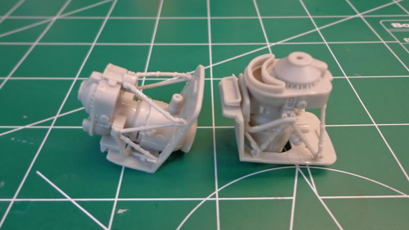
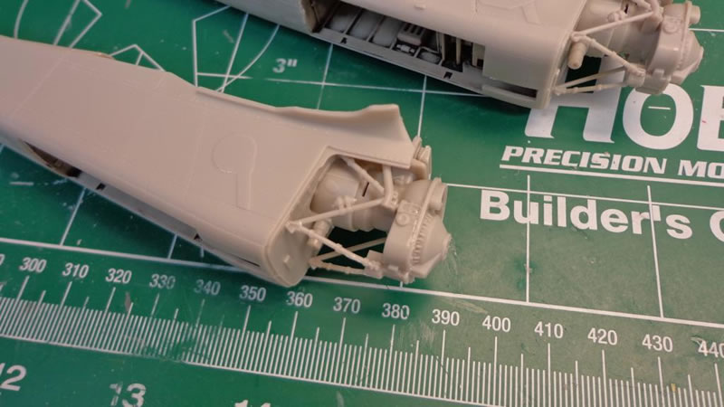
The next step after getting the cockpit and main fuselage components assembled was to start on the booms, which have the turbines in them as well as the wheel wells to complete. I started by assembling the turbines, which in my case were going to be closed up in the cowls since my build will be a more clean, buttoned up/panels closed look. I assembled the main components of the turbines, enough to make sure the prop was stable, but I did not worry about paint here:
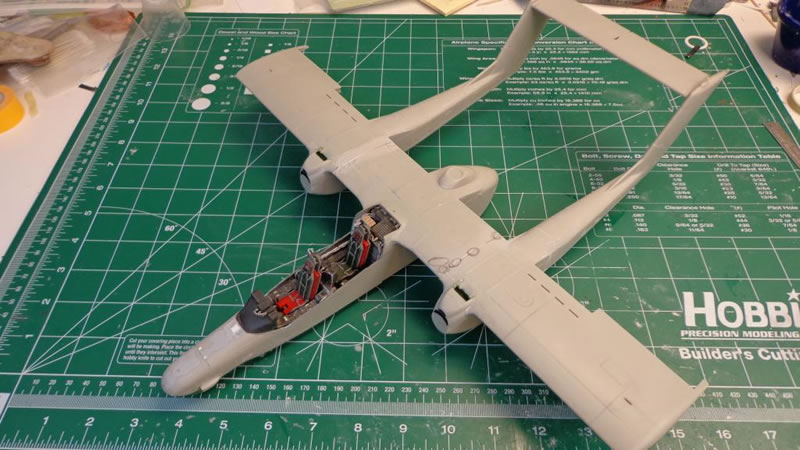
I also finished gluing up the troop door, as well as assembling the wings:
The natural method of installing these is needed here IE, the directions need to be paid attention to very carefully, as the outer wings are easily glued on the booms without any major issue, but the same cannot be said for attaching the boom/outer wing assembly to the fuselage/inner wing assembly.
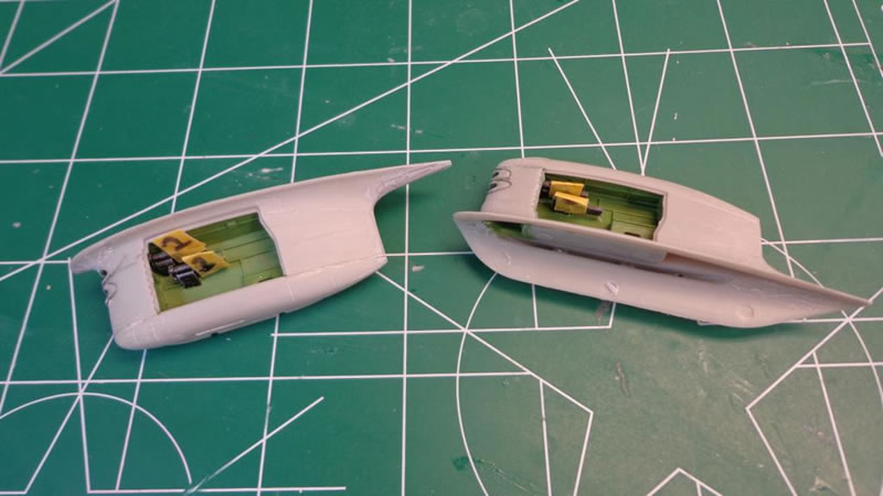
The Kitty Hawk instructions here call to install the turbine and turbine firewall inside the boom half prior to gluing the boom halves together, but I opted here for a different strategy, and that is to glue the halves together, then install the turbine and firewall assembly. This was concluded by the stellar fit of the firewall assembly when dry fitting the boom halves together.
This worked out very well and is highly recommended, as if you are like me, and don’t want the engine panels hanging out, or are posing in flight, you will need a tight bond between the cowl panels. The front cowl panel is directly seated on the intake on the front of the firewall assembly, and it is my recommendation that you install this front cowl to the engine/firewall intake first, and then install this unit into the cowl so the joint between the two side cowls and the top cowl is as tight as it can be. I glued in the firewall after the cowl was glued in, and this method worked very well.
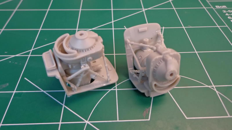
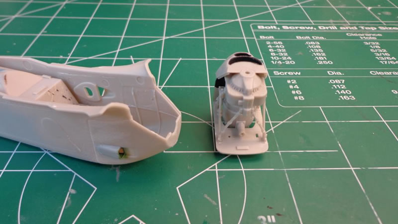
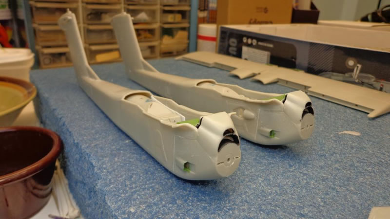
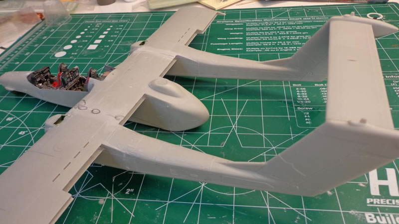
The booms were assembled, and the turbine/firewall assemblies dry fit:
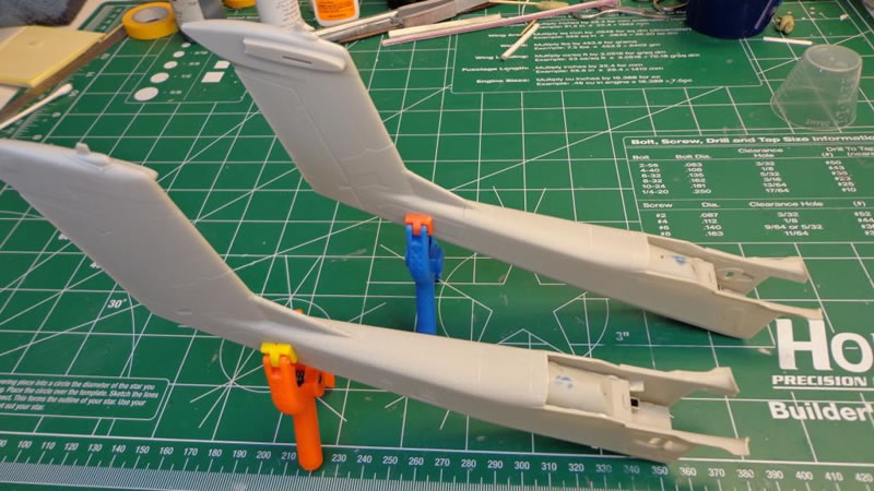
You can see here, that without the booms, it would be very difficult to fit the outer wing sections:
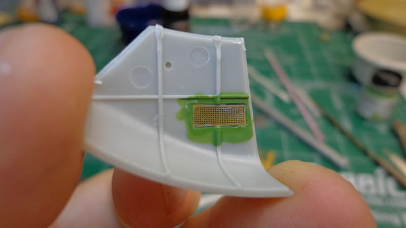
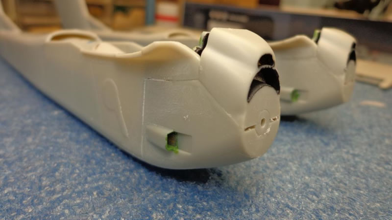
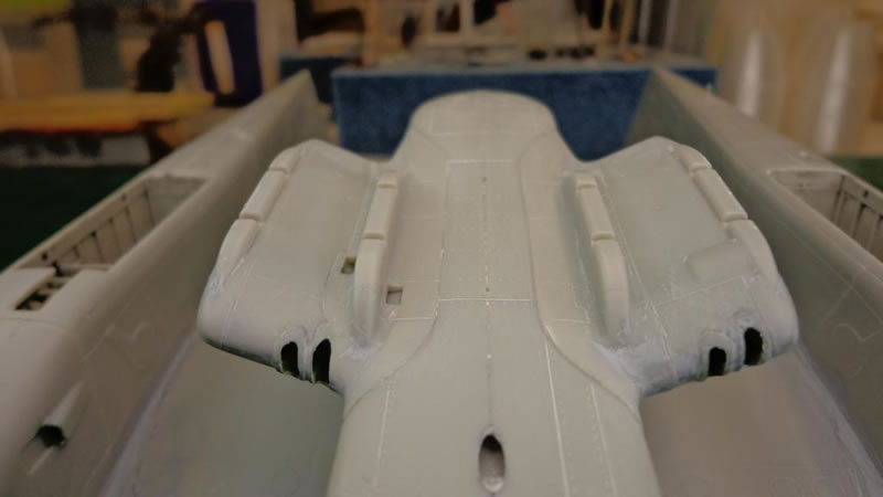
I installed the photo-etched cowl screens on the side cowl intakes for no other reason than it looked ugly and open otherwise, and I was too lazy to sand and fill:
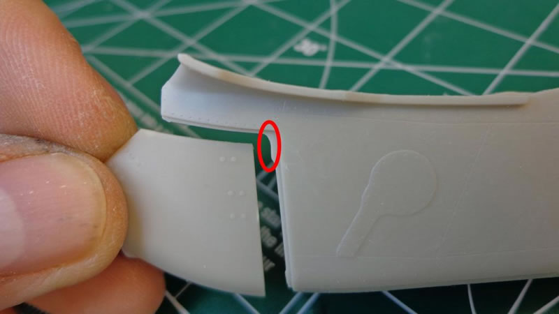
To get the cowls closed up properly, you have to nip off the inside corner of the cowl half:
I would also recommend dry fitting a lot to make sure none of the inner molded bracing interferes with the fit of the cowls. Another advantage of this method is that you can glue the two R&L cowl halves on, get that seam taken care of, then glue in the turbine/firewall assembly that has the upper cowl glued to it, and you get the tightest seams possible waiting to secure the firewall itself till last:
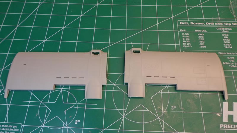
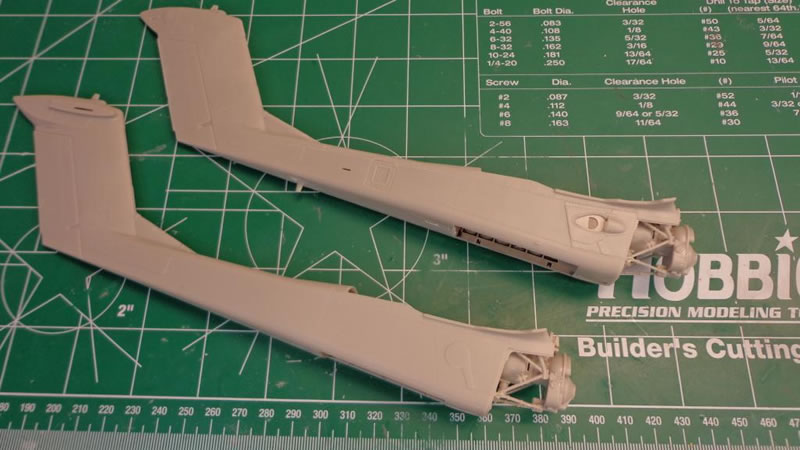
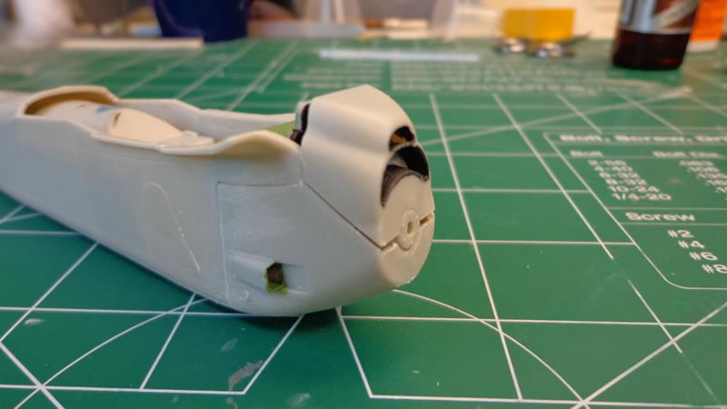
After both halves are assembled including the cowls, you can glue in the firewall assembly and complete each of the booms, along with gluing the upper spine top to each boom:
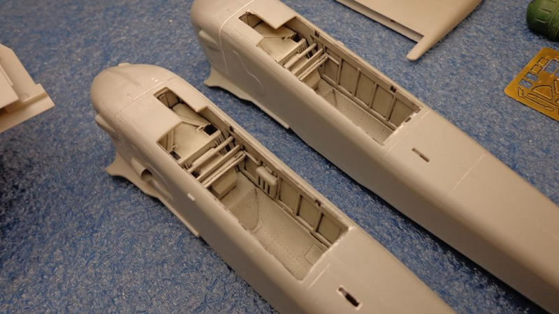
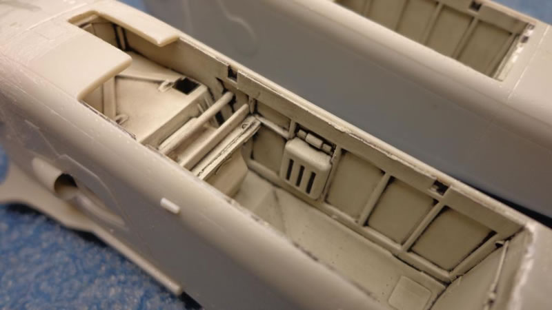
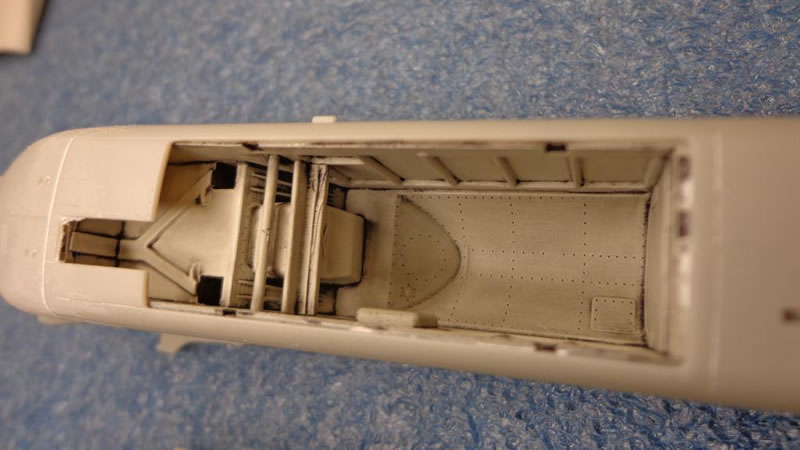
Although I’m showing it out of order, I did complete the wheel wells prior to the assembly of the booms. The wheel wells themselves do have quite a load of ejector-pin marks on them in quite prominent locations. These were dispatch the same way as the ejector-pin marks in the cockpit, with thick CA + micro-balloons.
I used the Kitty Hawk recommended color of camouflage gray MM36622 here, followed by a wash of Flory Models dark dirt. I do like this stuff, but it tends to go away if its left to sit on the shelf, and I'm thinking about exploring the UWW products. All the same they came out just fine for OOB, and I do like the well used, but not abused look:
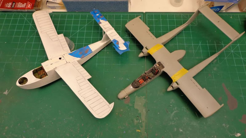
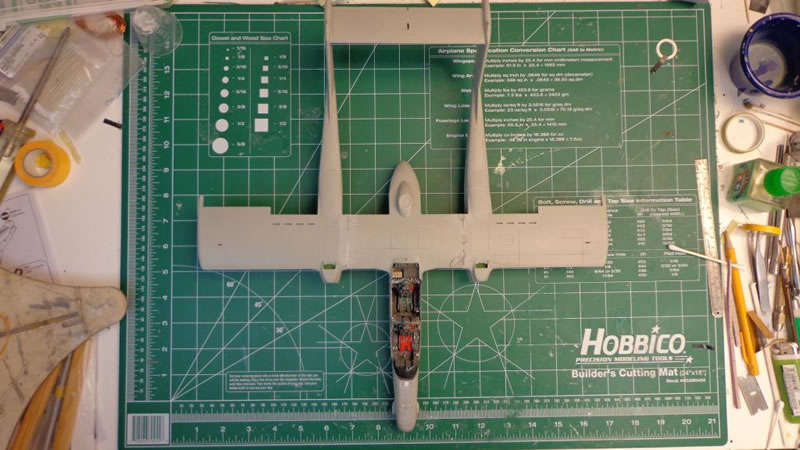
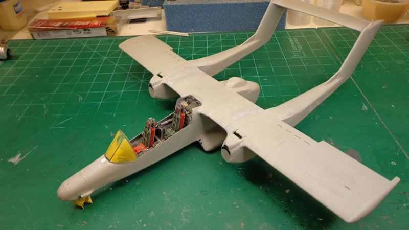
I glued the booms onto the outer wing sections per the Kitty Hawk instructions. Taping the wing and boom structure together reveals it has nearly the wingspan of my 1/32nd HpH Supermarine Walrus, and is longer by a small margin:
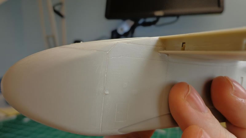
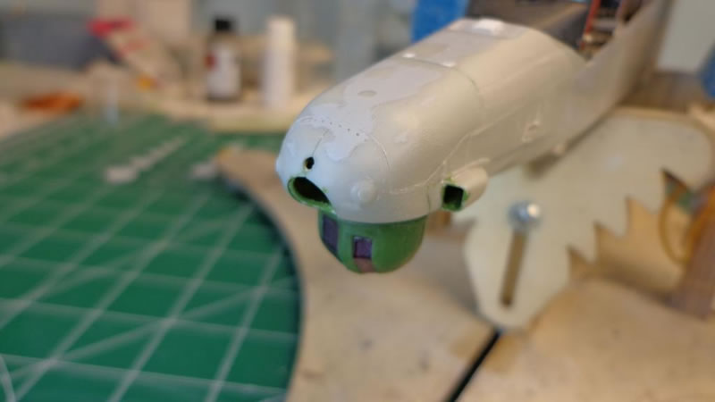
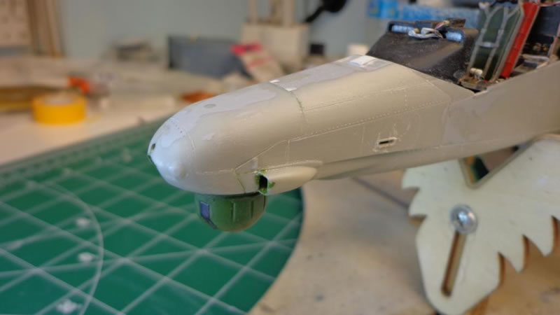
Next up, I glued in the front FLIR/laser ball, and got the nose secure and smoothed in:
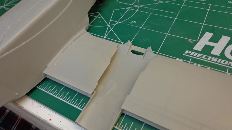
Now it was time for the next major step in this build, and that is the mating of the wing/boom assemblies to the fuselage/inner wing. After having done it, I can say I don’t honestly have a better way to do it myself, but I'm not a fan of how the wings and booms are attached to the main fuse. Its really dependent on getting everything aligned at the perfect point. I used some styrene strips soaked with Tamiya extra thin on the upper joints. The bottom joints follow the re-enforcing plates, so they are not straight at all. These are all butt joints so find a way to make them strong.
I would also recommend coming up with a small jig to keep things straight. I made mine out of flat sprue pieces. You can also adjust the booms alignment after they are glued on with some heat from an over the counter hairdryer, or even hot water but you need to be VERY careful if using the last method.
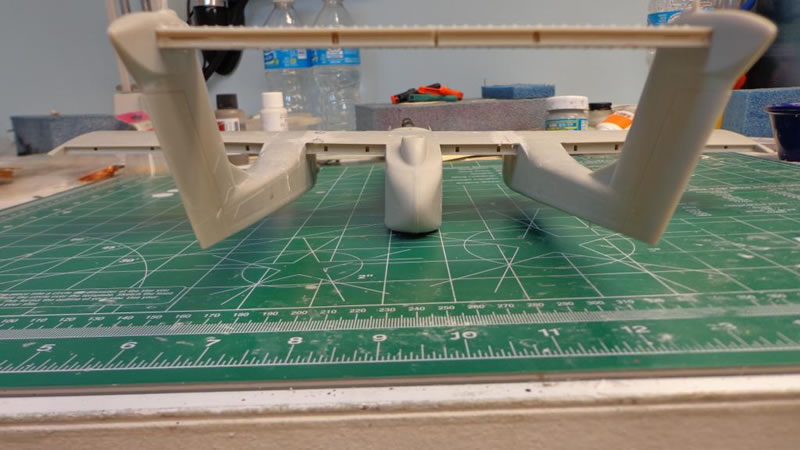
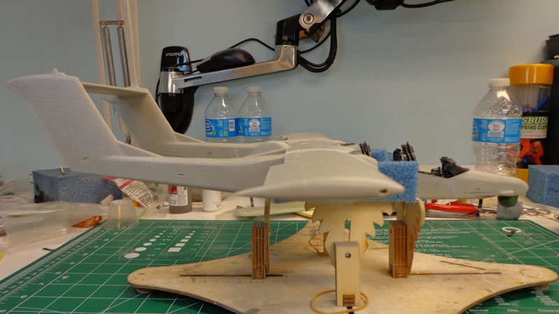
The OV-10 is deceptively big in 32nd:
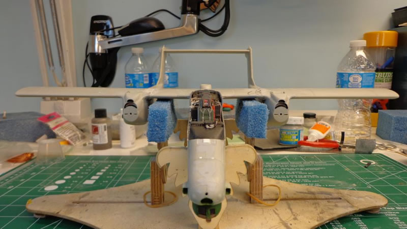
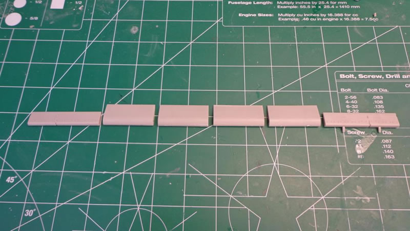
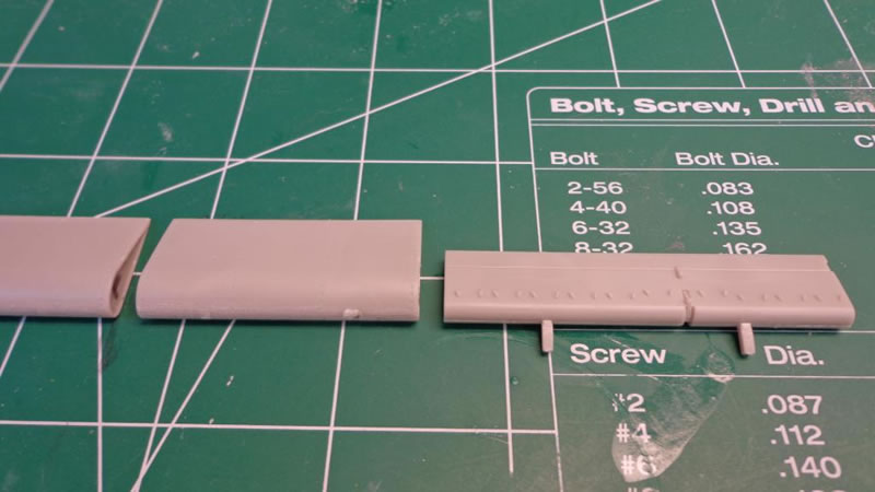
I also wanted to get the sponsons glued on, and the flying surfaces assembled. I started on the latter first, and got the flaps, and ailerons assembled, but with a slight twist. I really didn’t see many if any pics of OV-10s with their flaps completely deployed while parked. So I snipped off all of the connecting tabs for the flaps and one aileron, so they can be displayed in the retracted position:
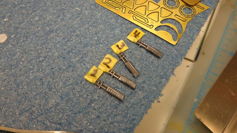
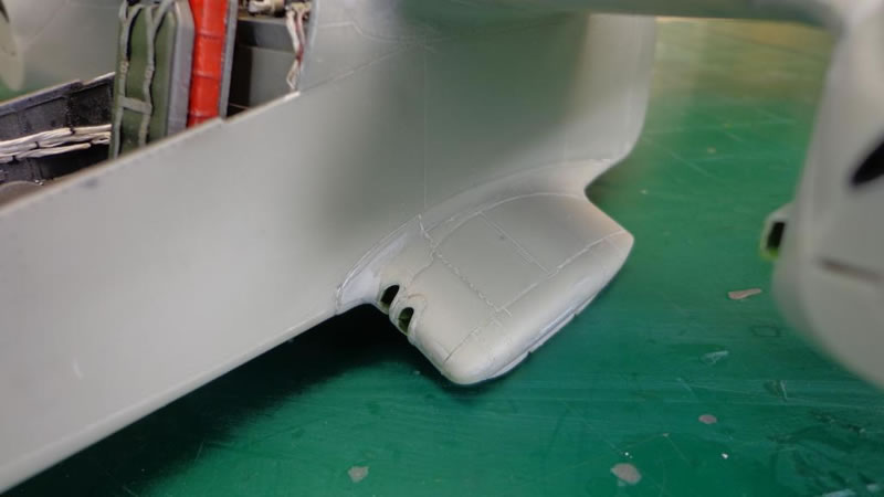
The sponsons really did fit well, but my only real issue with them was that you had to fully paint and install the .60 cals in them prior to installing them if you were like me, and were going to have the gun covers closed. My solution to this was to cut the guns right after the shell exit chute, and use the inner wall of the gun housing box inside the sponson to guide the gun ends in later after install. I hollowed the barrel tips out and logically numbered them 1-4 starting on the port side to keep things straight later:
If you take your time installing them, the very thin plastic at the edges will sand, feather and blend nicely:
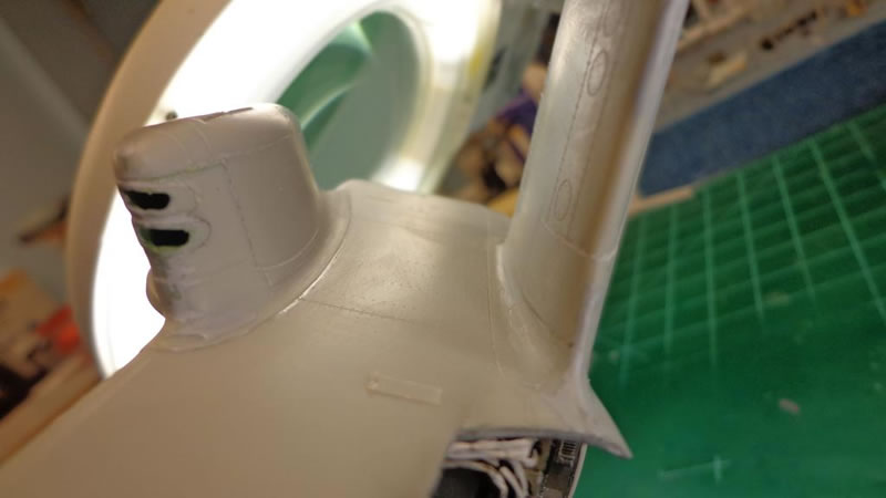
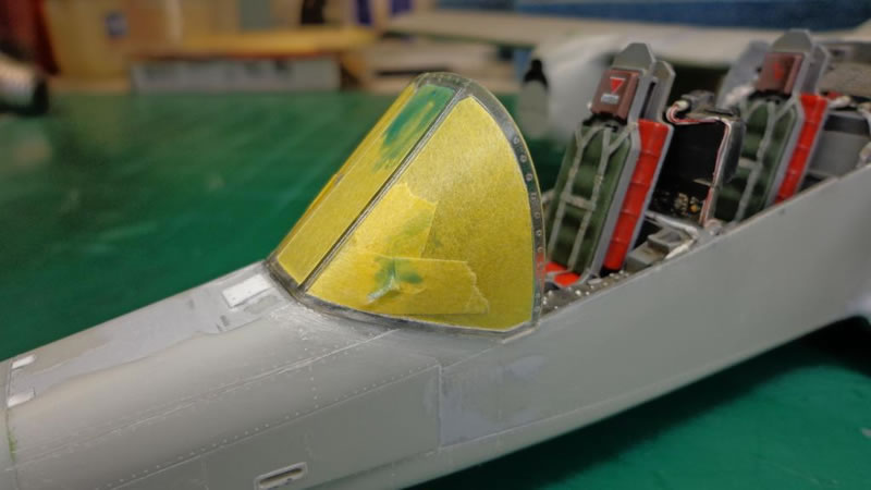
Lastly I got the windscreen glued in preparation to get all of the rest of the glazing put in the air-frame:
This is turning out to be a great fitting kit, and a really fun build. In my next and final installment of this three part build review, I will go over the painting, detailing and finishing of the kit, so stay tuned for Part 3: Paint and Finishing Details.
© Brian Leitch 2014
This article was published on Sunday, December 28 2014; Last modified on Sunday, December 28 2014