
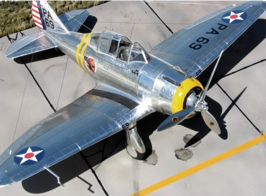
Williams Brothers 1/32 P-35 Part 2
By Mike McLeod
ENGINE COWL
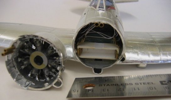
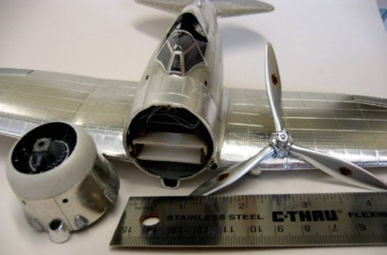
The engine cowl halves were glued together and the cheesy cowl flaps (just outlined with a thick raised panel line) were cut out. Engine fit was checked and mounting hardware fashioned. The cowl must be removable for battery access, yet tight enough that it does not look like it is "hanging on". By using two tight fitting concentric brass tubes glued together and parallel, I made a self-aligning mounting post to slip the cowl on and off. The inner brass tubes are just pegs that connect the outer pairs, which are securely glued to the fuselage or upper cowl.
These needed to be very tightly fitted as the gun exit troughs needed t be ground/filed/sanded on each side of the mounts. New cowl flaps were made from .010 and .005 sheet styrene with individual linkages behind each door. Exhaust pipes were drilled out and replaced with thin walled brass for a crisp look. Engine fit was adjusted and panel lines/rivets were applied to the cowl, making sure patterns aligned with the fuselage. Cowl fit was adjusted to ensure mating seam was minimal and would fade into surface like a panel line. The forward exposed gun barrels were made at this time and exit trough alignment checked. Thin wall brass tube was glued into the cowl to neatly accept the gun barrels during final assembly. The somewhat complex rivet patterns on the cowl were pin-stick applied. The larger cowl fasteners were made with a pin vise and small bit by just "starting" the bit to make a small circular divot that has relief and is larger than a rivet.
PROPELLER AND HUB
This kit has a nice prop design, but the molds left huge dimples and sinks in each blade. The hub has the basic shapes correct but the long, stretched up pillars simulating the fly-weights look terrible. The massive pillars were cut off clean down to the hub, and a small groove etched in. Scrap brass fret and styrene rod was used to make good looking fly-weights. The sink holes in the blades were filled in with medium CA and shaved with a scalpel, sanded with 600/1500 repeatedly until corrected. A thin aluminum tube ring was made to give the hub actuator a more 3-d look. Brass tube of the same size as the engine core piece was used to make a bushing which was fitted into the rear of the hub assembly to accept the steel music wire prop shaft without damaging the plastic hub assembly. The blades were attached on a jig for alignment and orienting in one planed of rotation. The entire assembly was polished with Crest and washed, painted with a nice "wet" finish of gloss black Model Master enamel, and set aside to cure for 5 days. The hub was finished with chrome ALCLAD II and the blades polished aluminum ALCLAD II. Decals went on nicely and the whole unit was final coated with Tamiya X-22 clear acrylic.
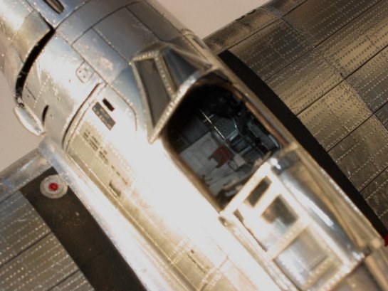
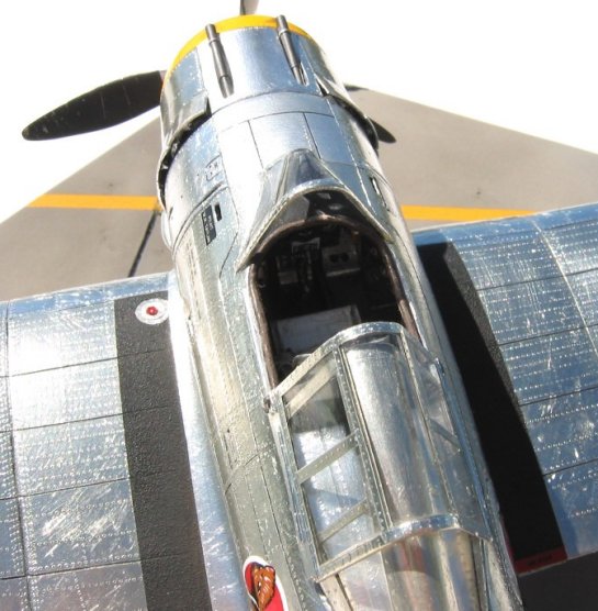
CANOPY
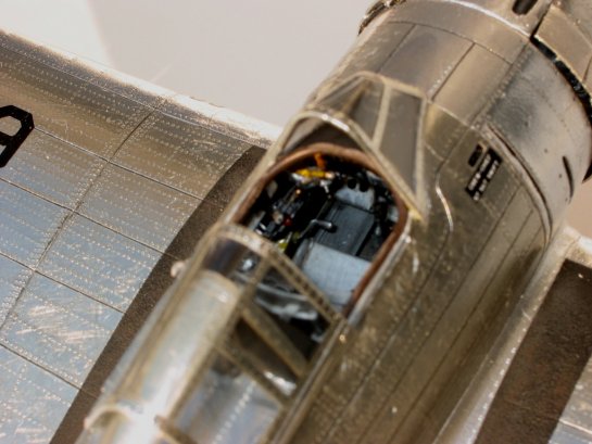
The clear canopy parts on this model are nice. They are packaged in a separate bag and were in good condition. Their fit is excellent and little sanding or rework was required. I cleaned up the pieces, scraped and pre-fit them, and dipped them in Future. Using a pin-stick, rivets were applied as required on the inner surfaces of each piece. Thin strips of Bare Metal Foil were applied and burnished on the inner surfaces. With the pin-stick again, rivets were applied to the outside and "matched" to each rivet on the inner surface. No foil was applied as this would be done in final outer covering. Points where the pieces would touch the fuselage and mate with glue were checked free of any foil. For the sliding canopy portion, two pieces of scrap fret were used to make the skirt which covers the canopy rail, and thin wire used to make the left side canopy outer latch handle.
ASSEMBLY
Here comes the good part…when the big pieces start coming together! The fuselage halves were mated taking great care to trap the tail wheel, aft cockpit bulkhead, and forward firewall correctly. The tail nav light wires were run under the left wing fillet, out of view, and in front of the forward firewall. Top and bottom wing outer/inner panels were mated and wires run through. Mating the outer and inner panels is a chore on this kit. The options exist for "without" (zero-dihedral racer version) or "with" (P-35). The mating points fit very tightly and nicely on EITHER the top OR bottom, depending on if you have dihedral or not. In this case, the tops were nice (preferred!!) and the bottom seam required large strips of styrene to gap fill…way too much for any putty or CA to handle! The entire wing was built up separately from the fuselage to ensure non-warped even dihedral. Now those non-connected panel lines and rivet runs can be finished up on the wings and fuselage. Then attach the wings and ensure alignment. At this point when checking alignment is when I noticed that the horizontal stab fairings on each side are not in alignment…YIKES!! The good part is that the stabs go in clean and straight, WHEW!! But this is what gave me fits when trying to draw in, and scribe the panel lines on the aft fuselage halves and the measurements always checked but the line spacing approaching the tail cone was not the same on each side. You see, it's always something… I ended up "flowing back" the panel lines to make them look correct, which turned out to get them aligned correctly……pure luck, man.
SURFACE PREP (AGAIN!)
Well, now it's looking like an airplane!! Go over everything and sand, fill, patch, re-scribe, touch up rivets, etc. to make it all PERFECT. Then polish lightly with Crest for a nice scratch free surface without removing any significant rivet details. Remember, foil shows detail well, and magnifies flaws beautifully also. The whole thing got a nice end-to-end scrubbing with a soft toothbrush an dish soap. I was surprised to see the bright gray plastic as it had become so brown and dingy from handling. Foil was applied to the rear canopy deck, and the windscreen and rear canopy greenhouse were glued on. Clean up the seams, which should not require any putty since the fit is so nice. Glue the battery box, made of thick styrene stock, to the forward fire wall as low as possible so the prop shaft will just glide across the top where the sweep contacts will be. I grouped the + & - wires together and stowed, then made/attached the braided copper sweep contacts on the top of the battery box. Now to make the colored lenses for the nav lights. I used stretched plastic in red, blue-green, and clear for the respective nav lights. Since stretched sprue has the same cross section, each piece was shaped to an "airfoil" shape, stretched to the appropriate diameter, and clipped to length. One end was rounded to the teardrop shape and pushed through the hole until just in position. The other side was marked for correct length. The piece was removed, trimmed, shaped, and polished, and reinserted. Once in perfect position, thin CA was wicked into the gaps, using a fine wire, to lock it in and seal the gap. Then the lights were tested…way cool! Little, itty-bitty red, green, and white lights. Remember, the green lens is actually a bluish-green, not the often misused Kelly green shade.
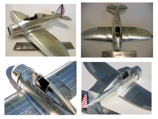
COVERING (VICE PAINTING…)
Well, there was actually some painting. With a clean, prepped airframe ready to go, the first step was to paint the control surfaces. Simply silver to match a doped fabric for the ailerons and elevator, aluminum for the inside of the cowl, and I chose to paint the rudder vice use the decal. Paint always looks so much better and it's fun to match up colors. The red and white stripes were not critical as good old Testors "little squares" matched the decals fine, but the dark blue leading edge took some tweaking of blue with a bit of black to better match the decal's blue on the insignia. Lots of Tamiya masking tape later, all the surfaces were done. While painting I also shot the main wheel wells with a mix of aluminum and a touch of steel, then sealed them with Future. Care was taken to mask and paint only areas not to receive foil as I wanted the foil on clean plastic and not over metallic paint or an oversprayed/feathered paint edge. And yes, a masked line will show through the foil. Now we reach the crux of the biscuit, and the foiling begins! Three grades of Bare Metal Foil were used; matte aluminum, chrome, and ultra-chrome. Most areas took chrome as the ultra- was far too stark and brilliant over larger areas. The ultra- worked well on select panels that showed high sheen in photos and/or stayed very clean. Some worn or varied panels took the matte aluminum based on photos showing relative sheen (obviously B&W pix, so a keen eye is handy for this part of your research!). Begin with the wheel fairings, then the cowl/cowl flaps. This will help you get the feel for foiling. When foiling, keep it clean! Any micro-speck of dust, hair, or debris that gets under the foil will show up looking like a rock is under the skin of the plane!! Keep a tack rag handy to wipe the surface before prep, and your hands as you work. Tools to apply the foil included; 1/4x1/4 medium balsa stick, toothpicks, q-tips, artists blending stumps, long fine tweezers, the pin-stick, and LOTS of #11 & #10 scalpel blades (X-actos are a bit dull for this, even if new). The balsa and toothpicks are shaped to have a chisel and a round end. Begin on the lower aft fuselage and work forward and up. Do tight spots like the elevator and vertical fin fairings before doing the surrounding fuselage and tail surfaces. The foil will come off quite easily if you goof it, just peel and do it over. It remains this way for several days to a couple weeks after application for some reason, after which the bond to the surface becomes stronger and more resilient. Then, it is almost impossible to peel off, and you will be picking at micro-chips of foil to remove it.
PAINTING
Now back to the airbrush. Care must be used at this stage to not damage the somewhat delicate foil job, which has not fully "set". The cowl and two stripes on this particular plane are insignia yellow and forget trying to match a cowl to decals…so all the yellow is airbrushed for consistency. To make masks for the stripes, the decals were scanned 1:1, and glue-sticked onto a layer of Tamiya masking tape strips applied to cover a wide area on a sheet of wax paper. All the decal stripes were carefully cut with care to save the non-decal space between the yellow stripe. These stripes are complex to fit around the tapered fuselage and canopy at an exact point and freehand mask jobs won't suffice. First, the forward yellow stripe was peeled off the tape, then the tape peeled from the wax paper and applied GENTLY on the foil. Do the same for the "space" between the stripes, then the aft stripe, and then the areas fore and aft of the stripes. When all is aligned and correct, GENTLY peel away the yellow stripe portion and GENTLY burnish down all edges. Mask off rest of plane from over spray and use some Tamiya tape to mask off the front cowl ring. With a q-tip, carefully swab the surface with denatured alcohol to clean, and give a light mist of X-22 to prevent bleeding. Shoot a primer coat of flat white, followed by just enough color to cover. Peel the tape away while wet to avoid tearing the paint, and don't score the edge or the foil will get cut and come up with the tape! Peel the tape S-L-O-W-L-Y, OR else, and when peeling pull it back at a steep angle, not straight up 90-degrees from the surface. You catch my drift by now.
WEATHERING
Huh!? How do you do that? On metal? Well, I feel that the foil surface allows the ultimate in replication of the look of a used and abused "NMF" plane. Referring to documentation showed a relatively shiny surface with lots of small, but highly visible surface scratches that are accentuated in various angles of light, especially in direct sunlight.
This is just impossible to do on any painted surface, no matter how good the silver paint may be. Weathering must be done on the bare foil surface, and done with care since the foil is so thin. FORGET REGULAR SANDPAPER, it will tear right through and really hack up the surface. On the cowl flaps I used a very light touch with scraps of ScotchBrite pad to gently, slowly, swirl in a dulled and worn surface. Once the surface has been ScotchBrited, is will take colorizing in the form of chalk pastel dust worked in with a blending stump if desired. For the general "scratching" a 1/32nd size foot was made from 1500 grit paper and glued on the end of a wood stick, This foot was gently rubbed, walked, and slid around in wear areas that the P-35 sustained such marks on. The paper becomes loaded after a short while and begins to need pressure to make fine blemishes, so glue on a fresh piece right over the first. Otherwise you may press too hard and get undesired results. Take your time, be patient at this point. After scratchin' it up a bit, the entire model was wiped down with Windex, avoiding the canopy. Don't use a solvent that may attack the foil adhesive. A light wash of black acrylic was applied overall and most excess was wiped away. When the look was satisfactory, the canopy was masked off and the whole thing given two light coats of Tamiya X-22 clear.
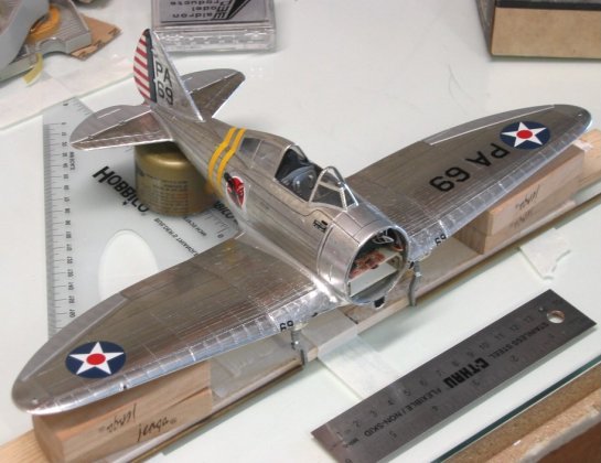
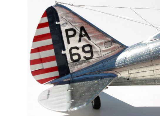
DECALS
I tested the decal response to solvents and found no bad reactions. The decals are very nice and not too thick, although there was a fair amount of clear edge on each piece. All decals were trimmed to eliminate as much of the clear stock as possible. For the insignias, no problem. For the buzz numbers on the wing, I elected to trim to a large rectangle and try to place the edge of the decal on a panel line or seam. Fortunately the clear on these decals is really clear, for it is hard to hide the edges when applying them over metal foil. All the sliders applied, I was faced with one last detail…the squadron insignia swooping hawk is printed in red-white-black. The real emblem had brown on the hawk, which was now red. After the decals were set up and wiped clean, the entire model, except canopy, was given another medium coat of X-22. When cured, the decals were nicely in place, protected and looked "painted on". Using some brown acrylic, so I could quickly wipe off a mistake, I painted in the brown where required using a 00000 sable brush. The brown acrylic is thin at this level of touch up and required several coats, making a hairy job three times more hairy!! Once complete, a quick shot of X-22 locked it in and protected it.
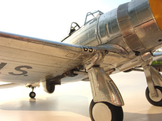
GEAR/ANTENNA INSTALLATION
When you've come this far on a model and it's looking nice, the last thing you want is to mess up the gear installation. When trial fitting the gear, it became obvious that the holes were too far aft and I re-drilled farther forward allowing the gear fairings to properly mate together. Test fitting the gear showed that ANY misalignment is VERY obvious visually and results in a noticeable wing tip unevenness. I had to guarantee that the gear would have a single axis running through each axle (no toe-in), and have the same rake angle/castor on each side.
Thus, a jig was fashioned on the bench to hold the aircraft and gear struts in perfect alignment while the 15-minute epoxy used to bond them in set up…giving me time to sweat over the program and tweak small errors. The jig used brass tubes, which fit the axles and are placed against a long wood straight edge. The fuselage was positioned 90-degrees to this and propped up with correct pitch to set gear stance. The end result was perfect. Very strong, perfectly aligned gear set in the proper mounting hole. The gear details were added next such as small linkage wires, retract/extension beams, strut placards, and brake lines. A unique feature of the gear is a naugahide or canvas like cover boot over the retract mechanism, attached with screws and large brass washers. This was made by carefully working wet facial tissue into the correct shape and place with the long tweezers and pin-stick. Once "perfect", small drops of thin CA were gently touched to it to wick in and turn it hard as concrete while securely bonding it down. This technique is fast, easy, fun, and looks great. When cured up, it was painted with a semi-gloss dark gray (best estimate of color, not much documentation here folks…). The precision punch was used to make the tiny washers, which were glued on with medium CA and painted brass. A small scrape with the pin made the screw at the center of the washer.
A little black and burnt umbra was used to streak a little oil down from the oil cooler aft along the belly, not too much though as is was a squadron CO's plane and kept pretty clean. All tires were slightly sanded for a flat spot and automotive putty used to give each a slight bulge to simulate weighted tires. One big headache, which plagued me from the start, was how to get "good" wing walks…and I still had not decided on a method. After experimenting with many suggestions using spray glue, baby powder, talc, spray 77, micro-balloons, thin CA, etc. etc. I still had not found an acceptable method to get that "just barely rough" finish, a little 3-D relief, be durable, and not too complicated. At last, the solution was elegant and superior to all the rest. Using some old Model Masters flat black that was getting thick, I sprayed the thick paint as-is at maximum pressure with medium flow from about 6-8 inches. The result was, as you guessed, lots of splattering paint! By masking the desired wing walk area, the spatters were built up s-l-o-w-l-y and formed the best looking, accurate, scale wing walk yet! A little rivet and panel line detail even shows through, and it has a slight raised edge. When cured up, the black enamel was more resilient than any other method attempted in tests.
Just mask, spatter away for a while, carefully peel off the tape, voila! Lastly, a little chalk pastel to show that a few people were walking on the stuff. The antenna on the P-35 was a monstrosity. I did this dead last, after the case was complete to avoid any "accidents", and you all know what I am talking about. Placing the 32-ga wire (2 strands) inside a small styrene tube and stretching it, then pulling out the wires made the fine white insulators on the antenna. Simple and easy.
The insulator cones where the wires exit the fuselage were turned down from a rod, glued in, and pin vice drilled to accept the wire. Using the thin 32-ga wire for the antenna gives a nice look and keeps the authentic metal look without getting into painting hair or stretched sprue, which I feel can be much thinner (and weaker) but just doesn't have the same look.
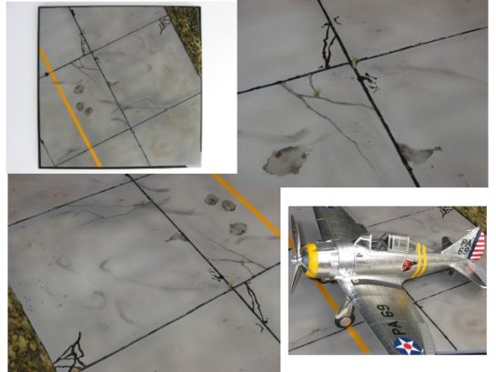
BASE CONSTRUCTION
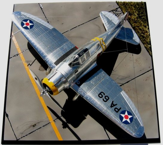
With all this effort I could not bear to see my shiny little pursuit plane sitting on a piece of oak or a black plastic slab. Thus, I took on the task of creating a suitable base to help display the model in a realistic environment. I chose to place it on the edge of a taxiway or ramp pad, almost in the grass. I found several photos with lines of P-35's, P-36's, etc parked along the edge of the tarmac in this manner. Since the case I ordered was 12x12x8, a 12-inch square wood floor tile was an easy start. The wood was trimmed to exact size, sanded and primed. After some trial and error, I settled on making the small patch of grass from several hundred small tufts of "range grass" I found in the railroad section of Space Coast Hobbies here in Melbourne, FL. On a piece of 3x5 card, I used a mix of carpenters glue with a few drops of burnt umber acrylic to glue down, endwise, short ¾ inch tufts of "grass". The grass comes in four colors; green, light green, brown, and tan. By making up bunches of selected strands, "mixing them up", and cutting to ¾ inch sections, I could make a pile of tufts to install over a 45 min period…then take a break! After all the grass was glued (no, you don't want to know how long it took…) some areas were touched up with a little extra glue for strength, and I used some hair clippers to begin "mowing" and shaping a bit of unevenness in the turf. Back to the wood, I marked out scale 16 foot x 16 foot slabs and used a Dremel cutoff wheel to make a groove between each slab. Where the edge of the ramp met the grass, I ground down the wood about 3/16th of an inch to allow "planting" the turf patch and getting a nice visual with the step down between grass and concrete. Much better look than "sprinkled on" grass. Using the back of an old # 22 blade, cracks were scratched into the concrete in an attempted random yet believable pattern. Crushed cat litter mixed with glue was spread in a few areas and when dried, the weakly adhering was removed. Color was added in layers by mixing various batches of gray, brown-gray, gray-tan, etc. and lightly airbrushing around to form a random look. Chalk pastels were used to create a few "low spots" where water puddles then evaporates leaving a bit of a water/mud stain. Some cat litter was spot brushed to look like ramp debris or stray dirt clods. Regular shiny black craft fabric paint was used to run "tar" into the grooves and make the faux patches. A quick run of Tamiya tape and some yellow mixed with a touch of orange (to ensure looked different than the yellow on the plane!) was stippled on for the stripe. To add that special extra item, small tufts of the grass were randomly placed into pin vice drilled holes and glued, then trimmed. I tried to make them look like stray weeds I have seen at airports sprouting up from the cracks.
OPERATION
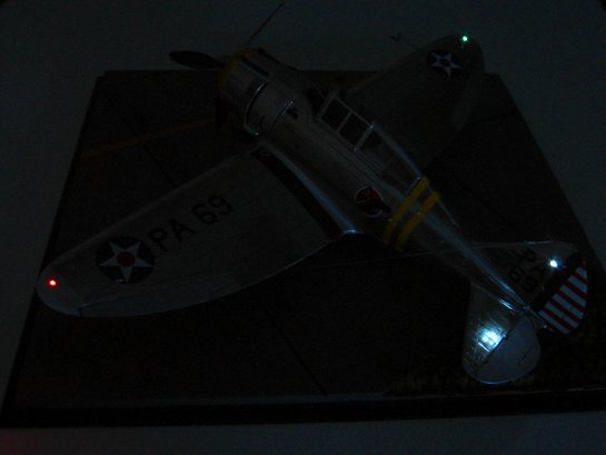
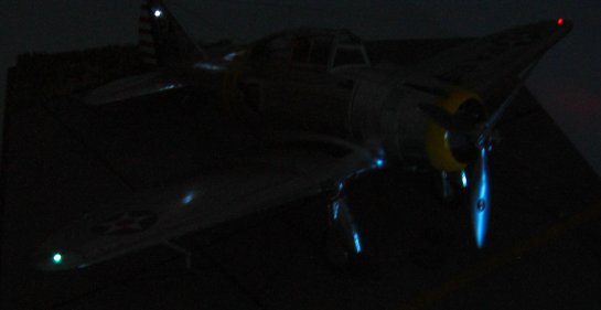
Since this model contains a battery, some design issues were addressed up front. No battery, wires, or switches can be visible from the outside of the model at all, period. The battery must be easily removable so as not to have to store it in the model (who wants a leaking battery in there!?). The way to access the battery must fully conceal the method, and operation of the switch should not be difficult, time consuming, or place risk on the model. With these self imposed constraints, the LED and 12V just barely fit the bill. After working out the arrangements for space, the top of the batter box became the location for the sweep contacts, which the prop shaft would short out. To make a simple switch, the end of the prop shaft touching the braided copper contacts was lightly ground on one half the shaft with a Dremel, and coated with thick CA. When hardened, the CA was filed and sanded to match the shaft, yet is non-conductive. With everything assembled and ready to go, the propeller is removed and a slight twist of the prop shaft with your fingertips makes the lights illuminate. Likewise, another twist to turn them off. I felt it a better idea to turn the shaft directly to avoid ANY forces on the prop for longevity's sake. I always make my props free wheeling and removable for transport and to avoid accidental bump damage.
© Mike McLeod 2002
This article was published on Wednesday, July 20 2011; Last modified on Saturday, May 14 2016