
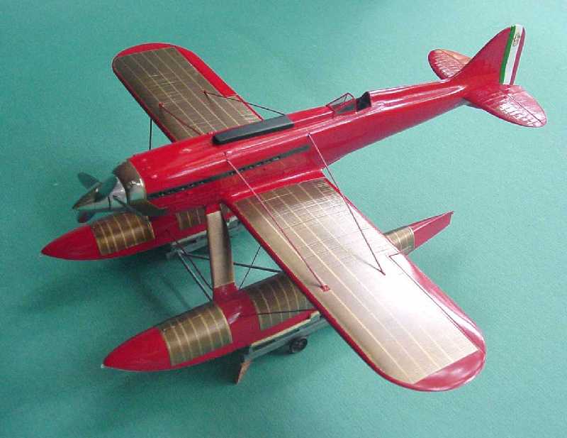
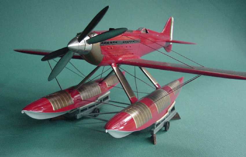
Essdale Models 3201 - 1:32 Macchi Castoldi MC.72 Schneider Racer
By Gene Nollmann
Back when the term "cottage industry" would conjure images of a model building enthusiast building and casting model parts and basic kits out of left over space in the kitchen (if a bachelor, which is quite likely) or the garage (if not totally consumed with storage), this venture came out of Bristol, England and onto the scene under the banner of "Essdale Models" with this first kit, no. 3201,sometime in 1996. The offering was one of the most famous and successful DNS"s in air racing history, the Macchi Castoldi MC.72 racing seaplane. Since then there have been other quite nice models of this same aircraft offered in 1:32 scale, namely those of Aerotech and Brach Models. Having acquired this Essdale kit before the others were made available, the author felt obligated to give this kit a go, even after so many years - one of those "Clear the Bench" stories!
Significance of This Subject
It has long been said that "necessity is the mother of invention" and so it would appear to be true for the Macchi Castoldi MC.72 and with some astonishing success. The "necessity" was to develop a more powerful engine but a shortage of time called for extreme cleverness.
The "moments" defining the final stages of the Schneider Trophy races can be seen as a 3-act play with the Supermarine S.5 winning the first act in 1927 and the Supermarine S.6 winning the second act in 1929. The third act would open in 1931 with Supermarine bringing back an improved S.6B and threaten to end the Schneider series with a third win in a row. Competition rules stipulated that the Schneider Trophy would go permanently to the country that achieved three wins within five years.
It is in that 2-year window from 1929 to the race in 1931 that Macchi Castoldi and Fiat were challenged to end the British dominance.
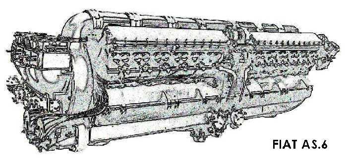
The Powerplant and Fiat AS.5 and AS.6
Engine talk can be a bit esoteric and boring, but this story is so pivotal to the outcome, it bears hearing.
A 1929 contract required Fiat to deliver a 2300 hp engine for the 1931 Macchi Castoldi racer to race for the Schneider Trophy. Fiat chief engine designer, Tranquillo Zerbi, realistically determined that 2 years was not enough time to design and run reliably a brand new engine. The necessity. His solution was a flash of brilliance with far-reaching and unknowable success.
Fiat had designed their own engine for their own plane, the C.29, for the 1929 Schneider Race, but it did not participate. The engine was designated AS.5 and was a 60 degree V-12 engine of the slimmest frontal area possible and displacing 25 liters with an output of 1000 hp and drove a prop concentric with the crankshaft center. Its power to engine weight ratio was the best of any of the engines running in the 1929 Schneider Races.
Zerbi"s solution of necessity was to basically use two AS.5"s in tandem on a common crankcase but with independent crankshafts and transferring power through gears to the V"ed middle of the blocks where concentric prop-shafts nestled to drive counter-rotating props. Now he had two 1000 hp engines giving a net 2000 hp. And with a modest supercharger boost of 5 psi (versus the Roll-Royce "R"s 17.5 psi boost), each half of the AS.6 was able to deliver 1550 bhp in 1934 trim for a total of 3100 hp from 50,000 cc! The rudimentary straight blade centrifugal supercharger took 250 hp off the rear engine and was compensated for by a fixed pitch change in the rear pair of propeller blades.
And the tally of results for using tandem V-12's:
- Twice the power with the frontal area of only one engine;
- Contra-rotating propellers eliminated adverse torque effect on the floats, allowing them to be smaller (in length and frontal area) and lighter;
- The geared power transfer to the blades allowed much more efficient prop tip speed than they could with the straight drive of the AS.5;
- It turns out the contra-rotating propellers more efficiently applied the power; the second prop had organized air to bite
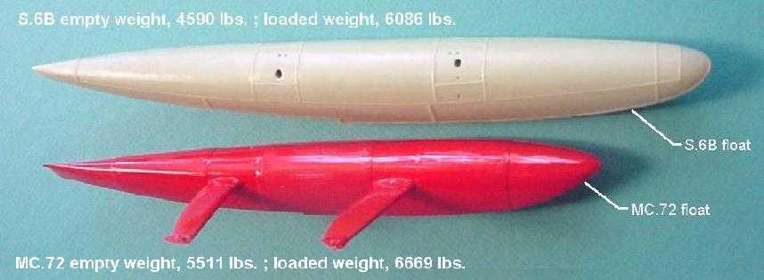
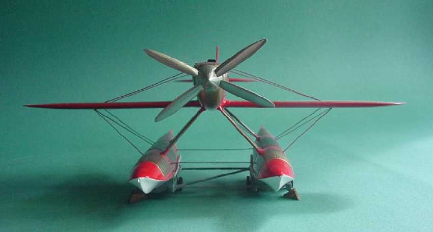
"Adverse torque effect on the floats" sounds relatively benign until you see the dimensional difference this resulted in. In the pic, note that even though the MC.72 was 10% heavier, the elimination of the torque effect allowed for a substantial reduction in the float displacement required to balance the craft on take-off and even more critical, a very advantageous reduction in frontal area.
With all these pluses and once the catastrophic back-firing problem, which prevented racing in the 1931 Schneider and had taken the lives of two test pilots, was solved, the MC.72 set a world air-speed record that stood as an absolute airspeed record until it was bettered in March 1939. And the MC.72 held an absolute speed record for seaplanes until it was broken August 1961 by a Soviet jet seaplane. The MC.72 holds an absolute world airspeed record for propeller driven seaplanes to this day, a blistering 440.68 mph set on 23 October 1934 by Sub-Lieutenant Francesco Agello.
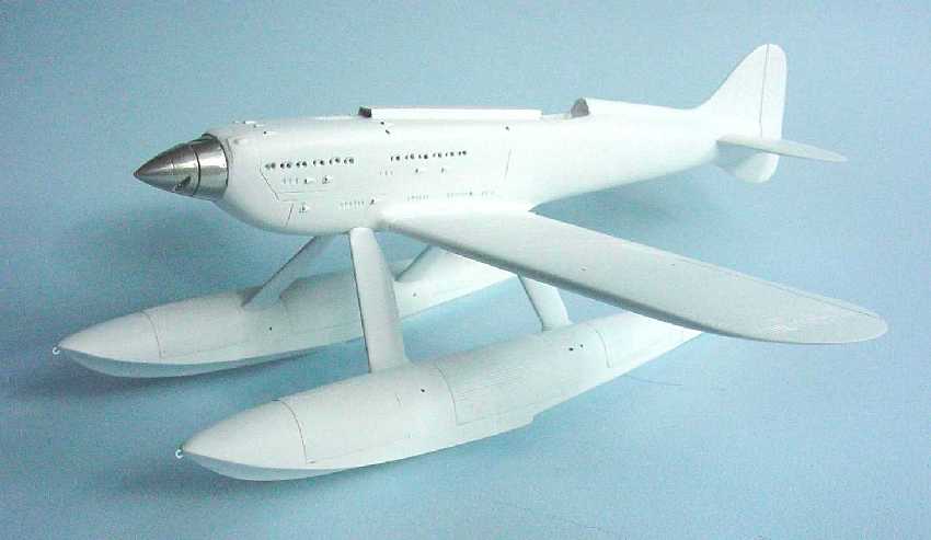
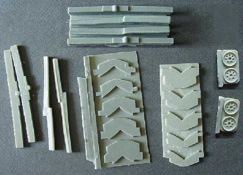
The Kit
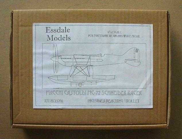
The kit comes in a modest brown box with a line drawing of the MC.72 glued to the top. It was broken down into 43 pieces; 33 polyurethane resin, 8 white metal, a decal sheet, and a small sheet of clear plastic from which to make the windscreen. The fuselage came in left and right halves with a single long tail section with a fixed rudder. Each wing was a unit and each float was a unit. A "bring your own" situation prevailed for the rigging and trolley axles. The rigging on the actual MC.72 is a neutral airfoil shape. The beaching trolleys were 11 pieces each - a nice little project to work on while waiting for gloss paint to dry. The kit instructions state the kit is presented in the form the MC.72 appeared in for its 1934 record runs.
The Challenge
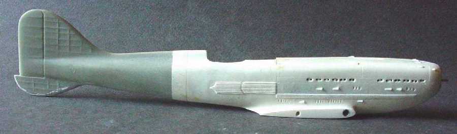
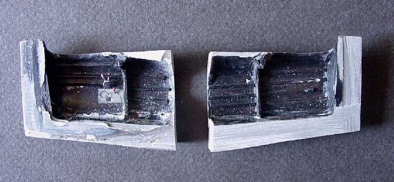
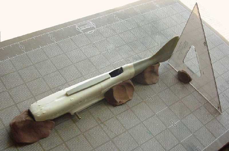
The kit was purchased from a modeler who abandoned the project after grinding off some major nose detail (on both sides) - probably in an effort to bring the wing roots into parallel to the fuselage centerline.
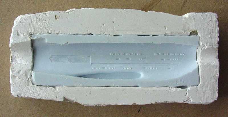
The only way to recover the lost detail was to replace the nose. A letter was sent off to Essdale Models, the fabricator of the kit, but remains unanswered to this day (and not returned as "no forwarding address") - it is an old kit long out of "production" and an answer would have been a real shock. The only alternative was to remake the nose.
Fortunately, limited access to an unbuilt kit allowed me to make a mold and then resin cast fresh pieces of nose. The damaged nose had a nicely built cockpit, so that was cut open and the cockpit pieces were salvaged to be adapted to the new nose.
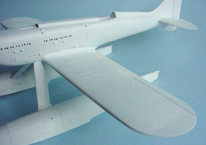
Surface Detail
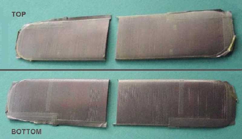
The surface radiator detail was very pronounced on the wings, floats and fuselage. Various race-plane literature described the wing as covered with "flattened copper tubes" and one ref" goes so far as to suggest that the assembled radiator skin was the actual stressed skin of the wing based on information of its interior design and construction. That being the case it would necessarily be able to keep out air under pressure to be able to suffice as a wing covering (this said with an eye to determine how the wing finish should "look").
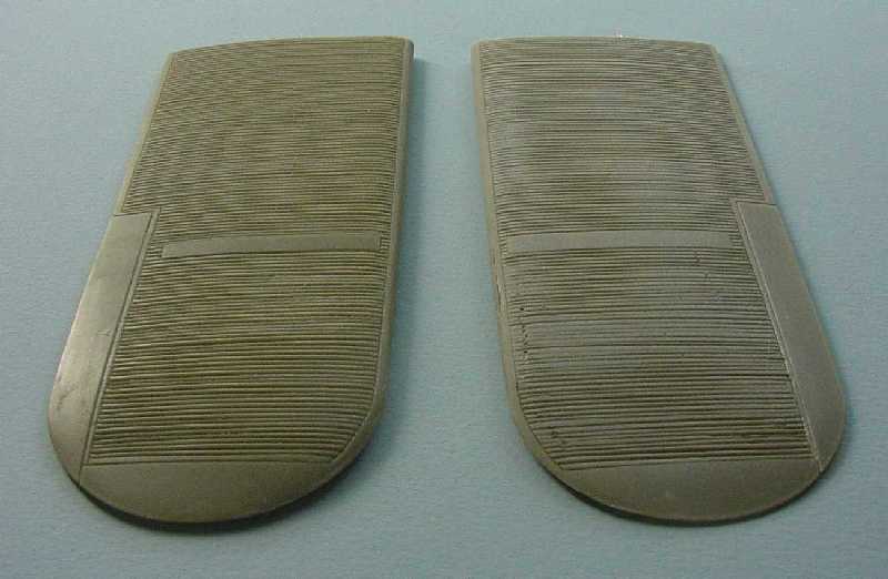
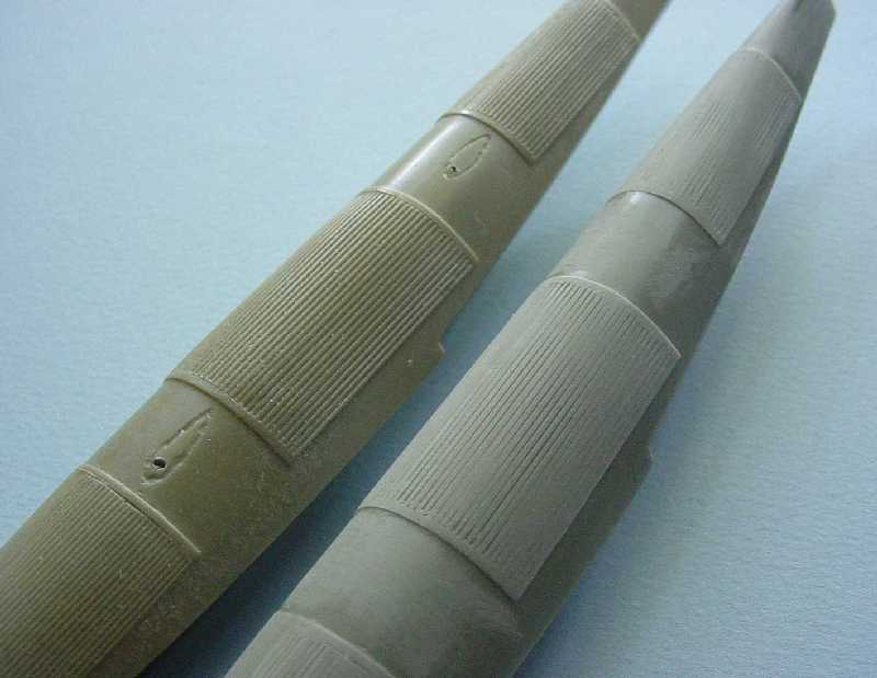
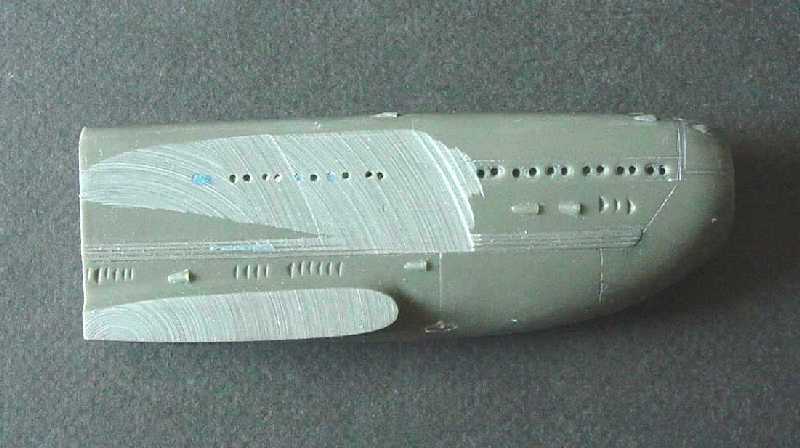
It is difficult to find a clear photo of the wing detail. However, the radiators on the floats clearly look planted onto the surface in the photo ref. But even then, they still look quite flat and smooth on the surface. On the Essdale model, the radiator detail appeared to be un-flattened tubes and the highs and lows were quite irregular and once presented in a bright metallic finish, the irregularity would be very pronounced. Jumping into the dark unknown, the radiator detail was block sanded down till it seemed to better represent the photos. Some "tubes" nearly disappeared while some troughs remained quite deep. After the wings and floats were primered, these troughs were filled with a special concoction of Tamiya acrylic paint (in this case white) and talcum powder (a.k.a. "Baby Powder"). It dries fast, sands easily and by using paint, it shrinks slightly as it dries and leaves some detail. The balance was not perfect, but came a lot closer to looking like a "suitable flying surface". (The Italian Air Force Museum has the last remaining MC.72 and has spent some time restoring it - the truth of its construction is out there somewhere - dilemma, wait for more research or build the model, being impatient you know what happened).
Surface radiators also appeared on the fuselage in various places at various times and were primarily applied and used during hot summer months. The fuselage radiators were the most discordant looking of all and this summer/winter option was a good excuse to present the fuselage with a "cleaner" look; however, the Essdale model had some of this molded in and had to be carefully chiseled off. That would leave me with a winter version and a clean looking fuselage!
Construction
Cockpit
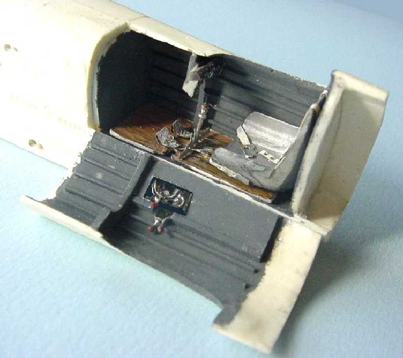
The Essdale model"s forward fuselage is solid except for an area blocked out for the cockpit. In recasting these pieces, an interior plug was used to make the fuselage nose hollow (there was some stray thought of opening up a panel to show an engine, but this was abandoned - later, seeing the Brach model gives some idea of how intense this modeling would have been to scratch build).
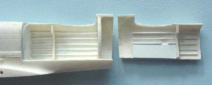
Stringers and bulkring were added to the cockpit walls of the new resin pieces and painted Gunship Grey (instructions call out black, but in that tiny hole the whole spectrum is black!). The seat and the instrument panel were pieces from the original Essdale kit; the control stick appears to have been a PE from some other source. Then the salvaged cockpit pieces were installed and the cockpit side panel glued in place.
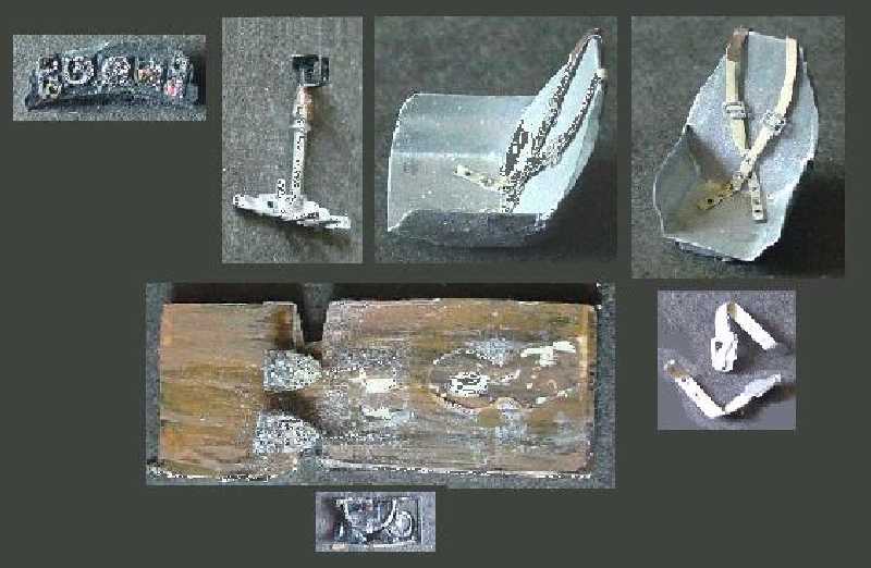
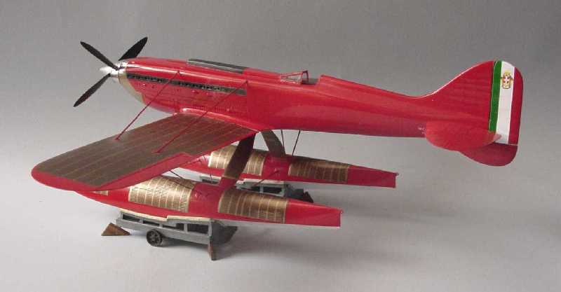
Trolley
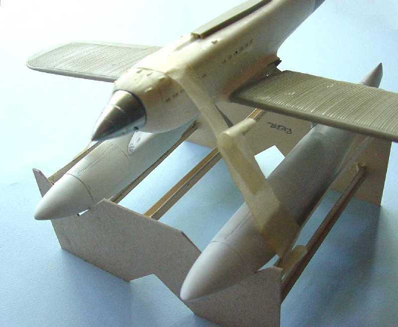
The trolley needed to be built for use in determining alignment of the floats. They turned out to be a bit more tedious to assemble that expected, but in the end they served their purpose. A few bits were added as suggested by various research photos; the corner block wedges for leveling the trolley and some tube spreader bars to maintain distance between the trolleys. The later served well to take some of the spreading forces of gravity off the strut-to-fuselage joints.
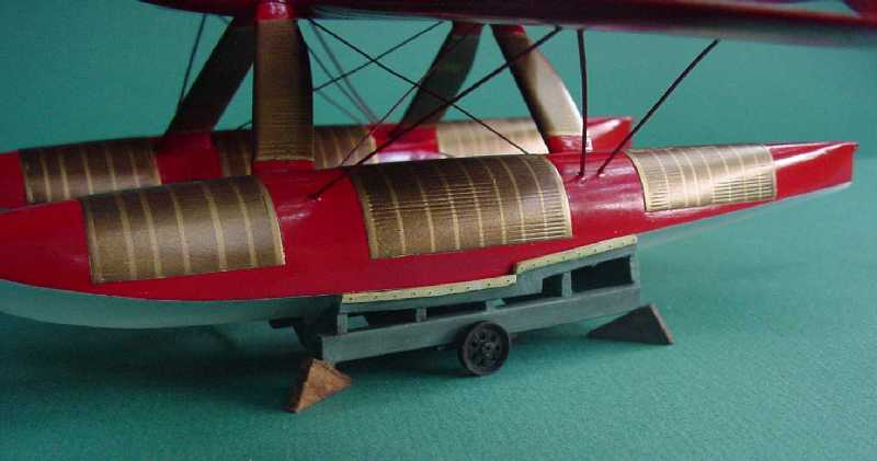
The trolley was painted up a dull blue/gray over a very dark gray base and then distressed a bit with course sandpaper. The cushion that reduces scratches to the floats was painted and aged to appear as canvas pads (the instructions call out black, but what material this represents is unknown - rubber?, but that didn"t seem very nautical).
Prefit
It is very advantageous while spraying gloss paints to be able to paint isolated pieces versus the whole assembled aircraft fuselage with wings, tail, etc. attached and in this case struts and floats. Finding that balance between too much gloss and a gritty dry coat would be nearly impossible and definitely impossible for me! Hence, some time was spent pre-fitting everything and pre-drilling for bracing wire attachment.
Props, struts, wings, and horizontal tail were drilled for brass pins to give strength to the joints and provide for repetition of alignment when final assembly approached.
The instructions provide full size drawings for making a jig to position fuselage and floats while fixing the struts in place. This was used in the pre-fit stage to develop a "repeatable" fit of all the elements. Thereafter, the jig, inverted, came in handy as a support while working on other elements of the model.
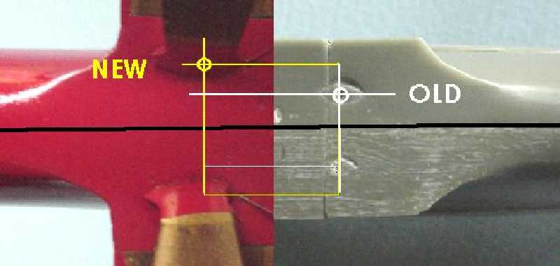
Cast into the fuselage were some marks suggesting a position for the rear strut attachment. These simply would not work. Mounting points further apart laterally had to be found and when found they also resulted in better alignment fore and aft. Further, in side view the fuselage sat in a more appropriate angle to the floats. This solution might not be correct, but the results seem to validate this approach. And need there be mention of how wonderful it is to get this "adjustment" process out of the way before there is a nice finish paint job to muddle at the end!!
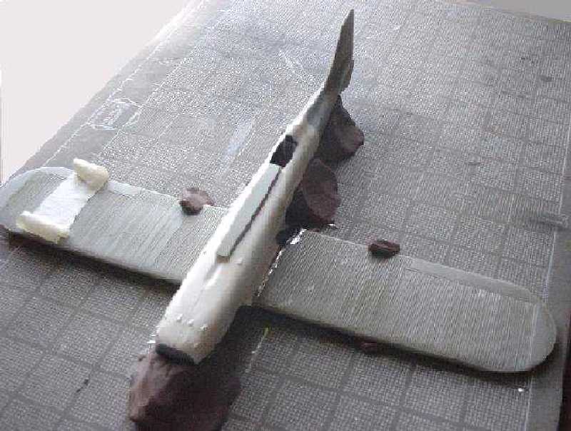
A simple cutting board grid was used to create a makeshift jig using hard clay to fix the wings and fuselage into position to assure ongoing alignment. The hard clay allowed positioning of pieces until axis alignment was achieved and then holding the position as the epoxy set. This was a critical area in the kit where the leading edge of the wing would not come to a right-angle to the fuselage unless serious adjustment was made at the wing root (remember the previous modeler"s grindings at the wing root).
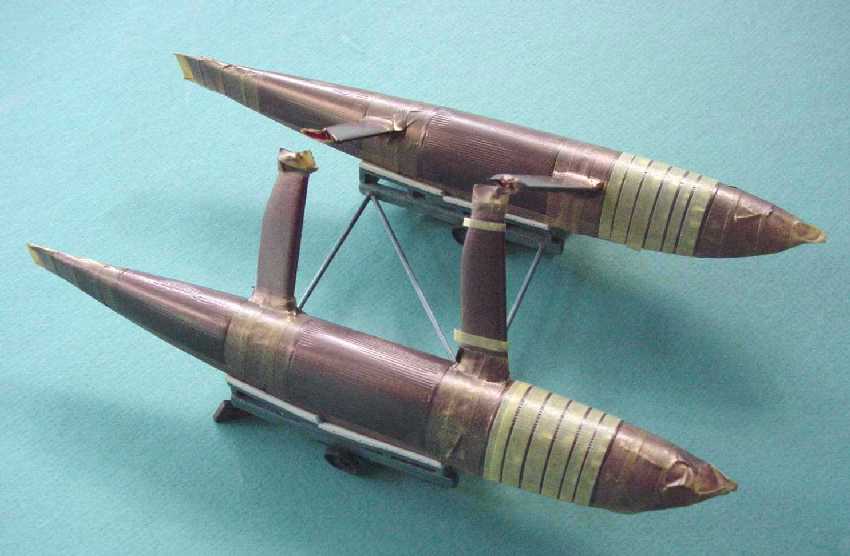
Struts & Floats
Anticipating some last minute adjustments, despite all the care to prefit, it was decided to bond the struts to the floats before painting - good thing! Some fill and surfacing was still required (imagine doing this with the color coat!). Doing this on the most visible connections was also a good idea.
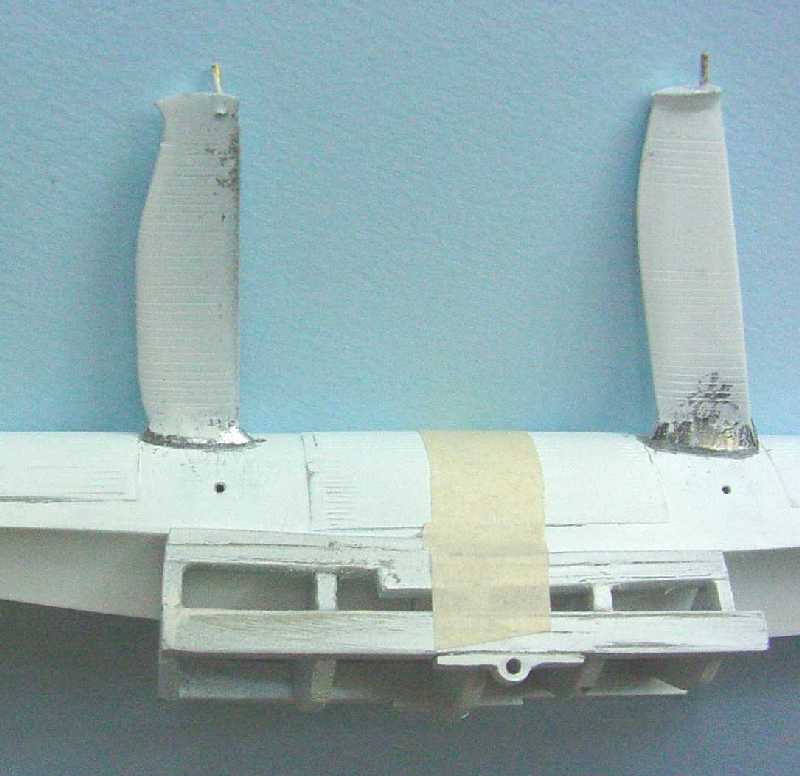
With some twisted wire, miniature eye-hooks were scratched and inserted in holes drilled in the floats fore and aft.
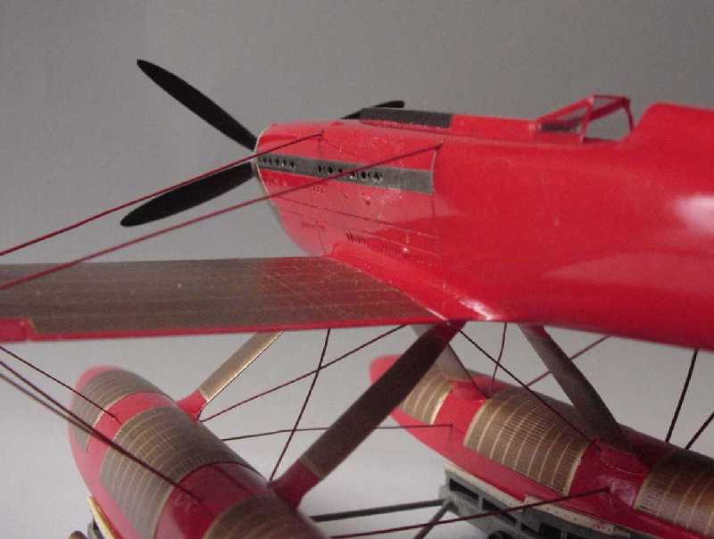
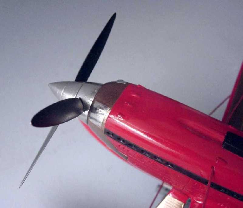
Counter-rotating Props
The prop hub came as a unit, i.e. at a preset angle of fore props with aft props. Not liking this too much, the fore and aft prop hubs were separated and each given an axle so that the fore prop would slip into the shaft of the aft hub - presto - now the angle could be adjusted to any desired.
Windscreen
The instruction gave a full-size flat pattern for the windscreen and a small sheet of acetate enough to make five or more. A light score line was scribed onto the cutout pattern for folds - once bent on the scoreline the acetate was nearly ready to fall off and if you attempted to bend it back flat, it would fall off. In the bent position, a small amount of cyano was applied to the break with a pin. Solid. Windscreen held its shape through all the ensuing abuse without complaint.
Painting
Main color
It was decided to use Tamiya"s paint system of White Primer (rattle can) and Italian Red (rattle can). There are all kinds of Red, but this one seems to have all the right pigment combinations.
Unlike the water and alcohol system of Tamiya"s bottle paints, the rattle can paints contain acetone and methyl isobutyl ketone among other paint chemicals and behaves very much like an acrylic lacquer (and can be polished to an amazing luster). As such, the metalizer lacquers seem to be compatible, as do the enamels. One caution; the cyano-kicker will do a wonderful job of melting the Tamiya rattle can paint (fortunately this discovery was made while using a pin-drop to set up a rigging attachment and the damage was quite tiny).
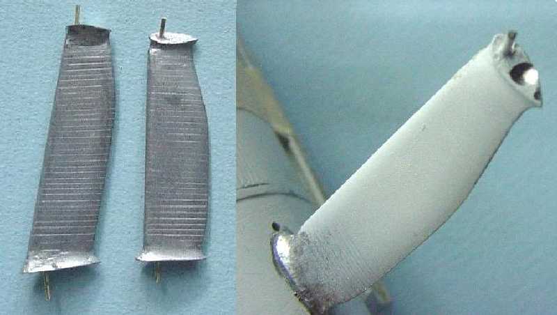
The props supplied were cast white metal. Essdale suggested they could be polished and they did polish up quite nicely and then were sealed with Future. The resin propeller hub was cut to allow counter rotation in positioning. The hubs were covered with Bare-Metal-Foil. It was a surprise to see the props and the hubs to have the same hue and sheen - especially considering the difference in metals (what is "white metal"?).
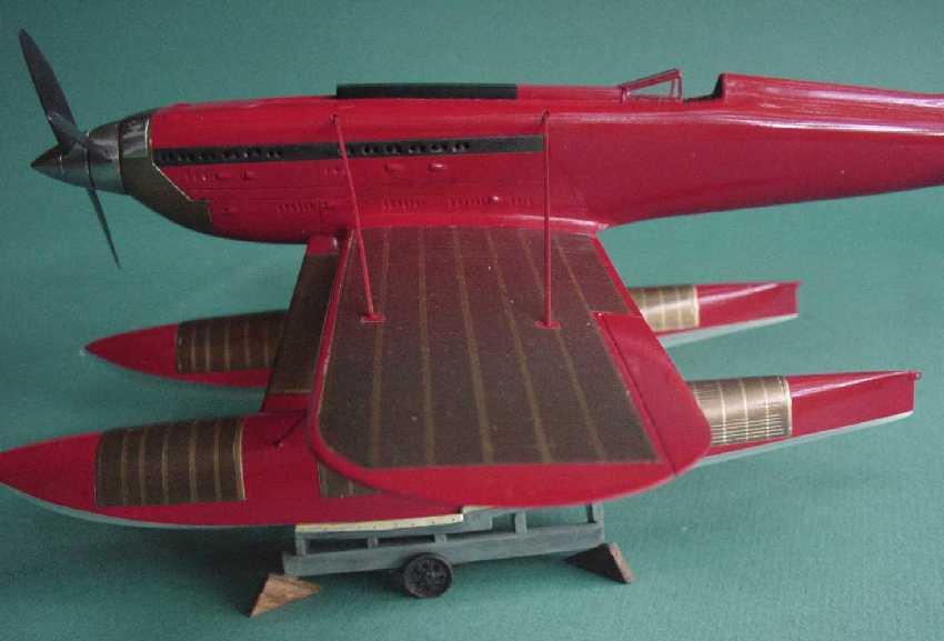
Radiator Finish
More thought and agony went over finding a solution for representing the wing and float surface radiators. In the end a multi-step process was adopted.
After the wings and floats received their red paint overall (and a suitable drying period) the radiator area was taped off with Tamiya masking tape (an excellent product and caused me to reflect on how much Tamiya has given to the enjoyment of modeling, not just great models, but an intense line of high quality products to help you build those models to a very high standard).
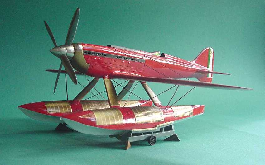
Masking complete, all the surfaces were given a coat of Gunmetal (buffing) Metalizer mixed with a generous amount of Pearl Ex Pigments Super Copper. Enough was added to clog the airbrush in quick order. To the mix was added Metalizer Thinner; then all sprayed on well. This gave the radiator areas a dark base that still had the tone of "copper tubes". The finish was buffed but with some Pearl Ex Pigments Aztec Gold [Brass] dry powder generously applied to the buffing rag and surfaces. This powder is very small (they say 10 to 60 microns) and will find places to adhere even to a glossy surface after buffing - quite interesting product. At any rate after the buffing the radiator surfaces had this quite nice copperish/brassy patina. The pics almost reveal this.
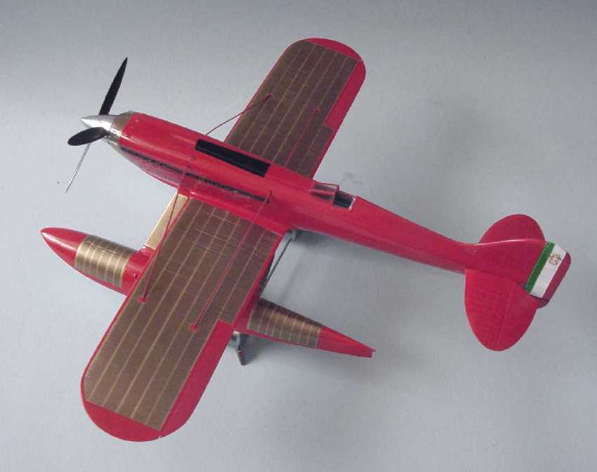
This was given a coat of Metalizer Sealer - all behaved well. After a couple of days, all was masked off, again with Tamiya tape, to created the border and interstitial lines that often show up as bright metal in some of the ref pics. A clear lacquer coat was applied after the taping to encourage blockage of wet paint under the tape; the clear would do the migrating and block the following color coat from migrating under the tape. This was sprayed with Metalizer Brass (non-buffing) and an amount of the Pearl Ex Pigments Super Copper - the purpose here was to knock down some of the brightness of the straight Metalizer Brass. The tape was removed, the clear coat and Tamiya tape did its job, and all was happy with the "Essdale model team" (i.e. me).
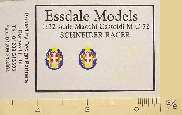
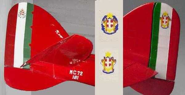
Decals
The division of color on the rudder follows the full size drawing provided in the kit. However, the "crest" that appears in the white band has some squiggly blue lines on the sides of the crest which do not appear on the museum plane and also is too wide for the model. With the "blue" trimmed off, all fits and also matches the museum plane. The only other decal is the faint identification "MC.72 181". There were 5 planes produced, nos. 177-181; no. 181 is the one that set the world records and is the one in the Italian Air Force Museum in Vigna di Valle/Rome, Italy.
Last of all - Rigging
The MC.72 used bracing wires to keep the wings, floats, and fuselage all in their proper alignment. The wires were very flat and said to be of an airfoil shape. To simulate this, a soft copper wire of 0.031" diameter was filed and sanded flat on two opposite sides until a size of 0.031 x 0.011 (roughly 1"x 3/8" in scale) was achieved. The holes drilled were to be deep enough to receive an extra length of wire and facilitate rigging.
Conclusion
At one time in 1:32 scale we had to look to "cottage industry" kits, be they resin, vac or other, for some of the most mundane modeling subjects. Today mainstream and limited injection kit manufacturers are gradually making kits that obsolete the former "cottage industry"s bread & butter (ten years ago who would have thought that Scratchbuilders, Craftworks or JRutman's product line would be almost completely run over by mainstream kits!), but there will always remain enough marginal subjects that the "cottage industry" can offer that promises too small of a market to attract the competition of a mainstream manufacturer. The Macchi Castoldi MC.72 might be one of those subjects on safe ground and has been the focus of more than one "cottage industry" kit maker.
The Essdale Models offering, though now long out of production, might be a cut below the Aerotech offering, but it remains a basic kit that can respond to a little attention. The basic elements are there and they require some fundamental modeling attention, but it will build up into a handsome model without hundreds of hours of benchwork (but would certainly respond well to that if desired).
With so many diverse elements coming together on this subject, the necessary exercise of prefitting and adjusting cannot be over emphasized; without it, the final assembly is doomed. There was nothing major required, like cutting and reducing or enlarging a part; all issues came to the consideration of placement and then some filler and clean up at the joints.
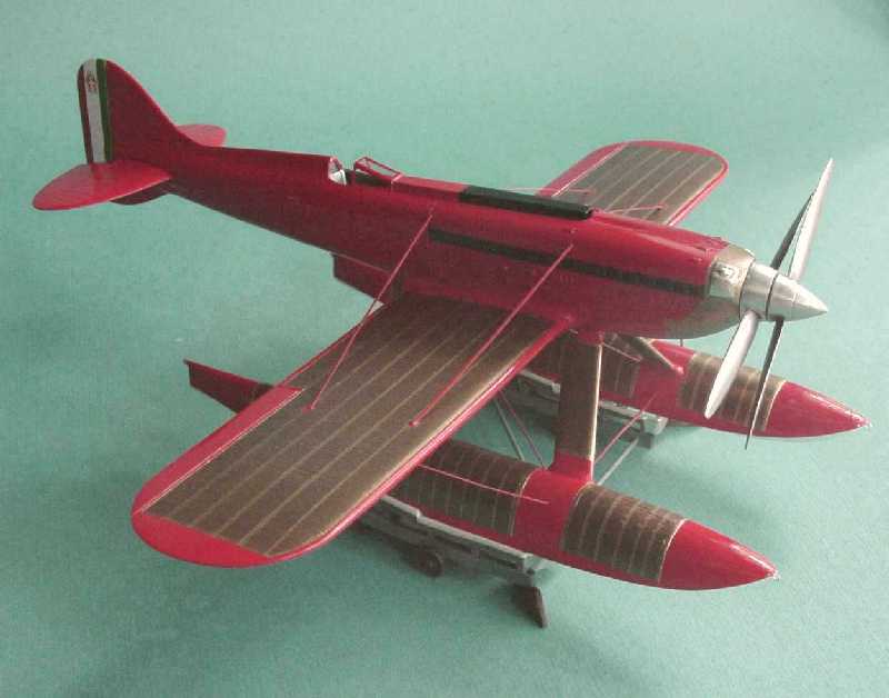
The result can be a handsome representation of an historically significant aircraft and one that not only broke and held records for performance, but one that has earned a seat among the "classic" expressions of the "industrial design" art - up there among the 1952 Studebaker or the Raymond Loewy steam locomotive.
Products Used
Glues
- Zap-a-Gap PT-04 - Medium CA+ [cyanoacrylate]
- J-B Weld - Epoxy Steel [2-part slow curing]
Paints
- Tamiya 87044 - Fine Surface Primer (L) (White) [rattle can]
- Tamiya TS-8 - Italian Red [rattle can]
- Tamiya TS-26 - Pure White [rattle can]
- Hobby Color H26 - Bright Green
- Model Masters 1723 - Gunship Grey (interior color & trolley base color)
- Hobby Color H67 - Light Blue (trolley top color)
- Pearl Ex Pigments 655 - Super Copper (Jacquard Products)
- Pearl Ex Pigments 658 - Aztec Gold [Brass] (Jacquard Products)
- Bare-Metal Foil Co. - thin self-adhesive aluminum foil
- Model Masters Metalizer 1405 - Gunmetal (buffing)
- Model Masters Metalizer 1417 - Brass (non-buffing)
- Model Masters Metalizer 1459 - Metalizer Sealer (non-buffing)
- Testors 1260 - Dullcote, Clear Flat Lacquer Overcoat [rattle can]
- Microscale Industries MI-12 - Liquid Decal Film [holds fragile decals together]
Other Modeling Aids
- Tamiya masking tape
References
- Racing Plane and Air Races: A Complete History, Vol. III, 1932-1939 Reed Kinert Aero Publishers. Fallbrook, CA. 1967, 2nd Prtg., revised, 1969 ISBN: none (pbk) (96 pp) [no mention of MC.72 in Vol. II, 1924-1931]
- Schneider Trophy Racers: History of the Schneider Trophy International Speed Contests 1913-1931 Robert S Hirsch MBI Publishing. Osceola, WI. 1993 ISBN: 0-97938-616-9 (hc) (192 pp)
- The Schneider Trophy Story Edward Eves MBI Publishing. St. Paul, MN. 2001 ISBN: 0-7603-1118-8 (hc) (253 pp)
- Schneider Trophy Aircraft 1913-1931 Derek N James Putnam. London. 1981 ISBN: 0-370-30328-8 (hc) (305 pp)
Not available to me, but maybe useful:
Aeroplane, November 2004 - has article & color photos
© Gene Nollmann 2004
This article was published on Wednesday, July 20 2011; Last modified on Saturday, May 14 2016