
Supermarine Spitfire Mk VIII
Photos By Max Otten
Photos were taken at the South African Military History Museum, Johannesburg (South Africa) in 2015.
The Spitfire VIII at the Museum has extended wing tips, and a bare-metal finish (not silver painted) with the rivets standing out in darker color. Fabric control surfaces (elevators, rudder) are painted silver. It is equipped with wing leading-edge fuel tanks. The Spitfire displays the number 5501 on the side. According to Wikipedia this is its South African Air Force (SAAF) serial number. The original serial number is JF294. Morgan and Shacklady list its details as delivery 19-1-1943, Merlin 66, in Oct 1943 transferred to the SAAF, flew non-stop Cairo to Cape Town March 1944.
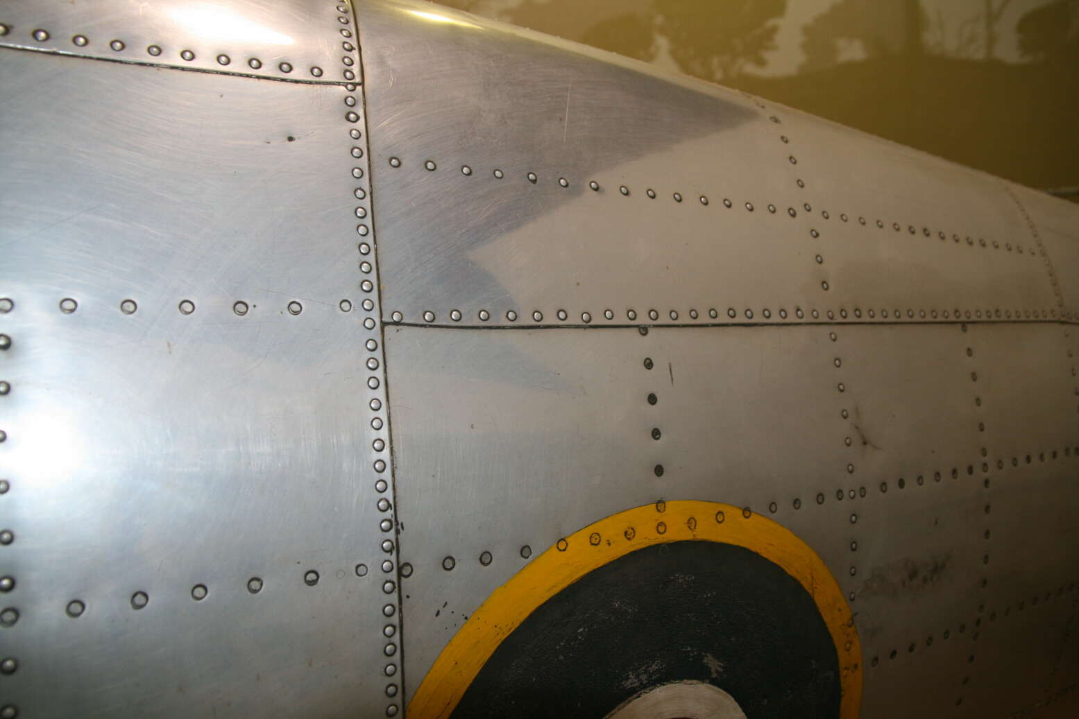
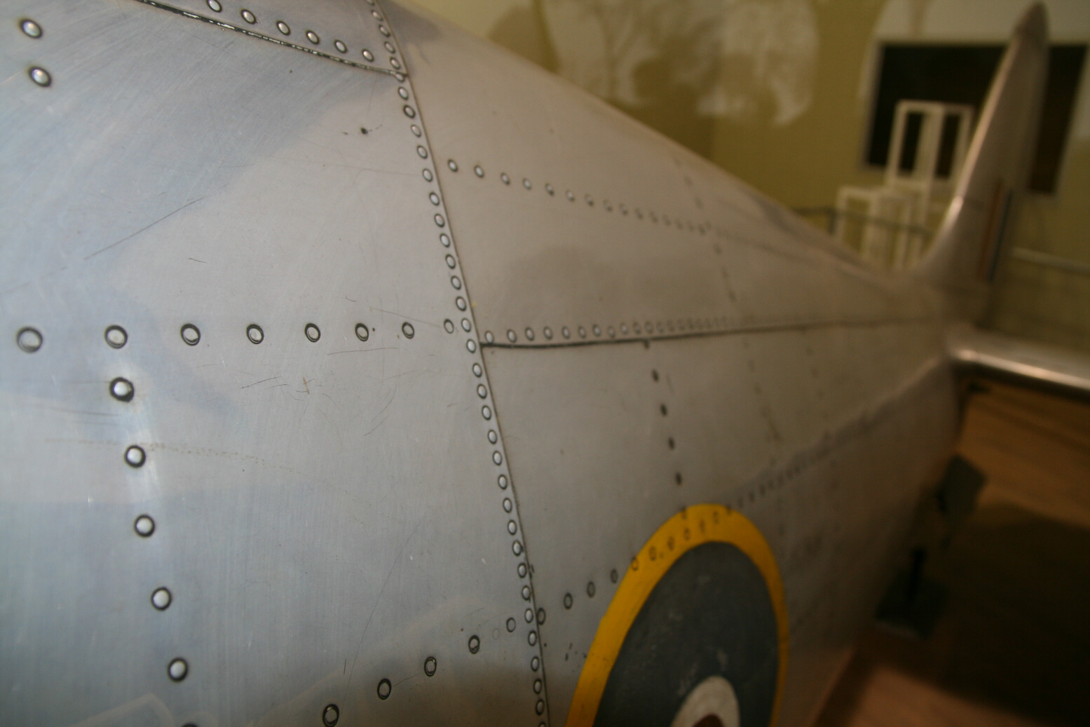
Photos 1 through 3 (below) show an overview (as far as can be achieved in view of the limited walk-around space) and details of the nose.
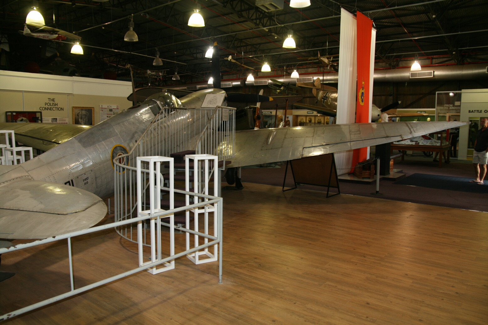
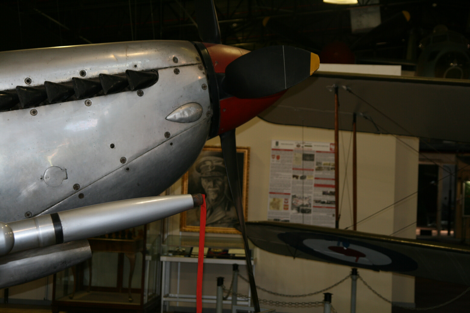
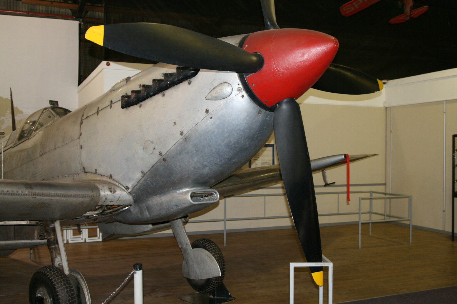
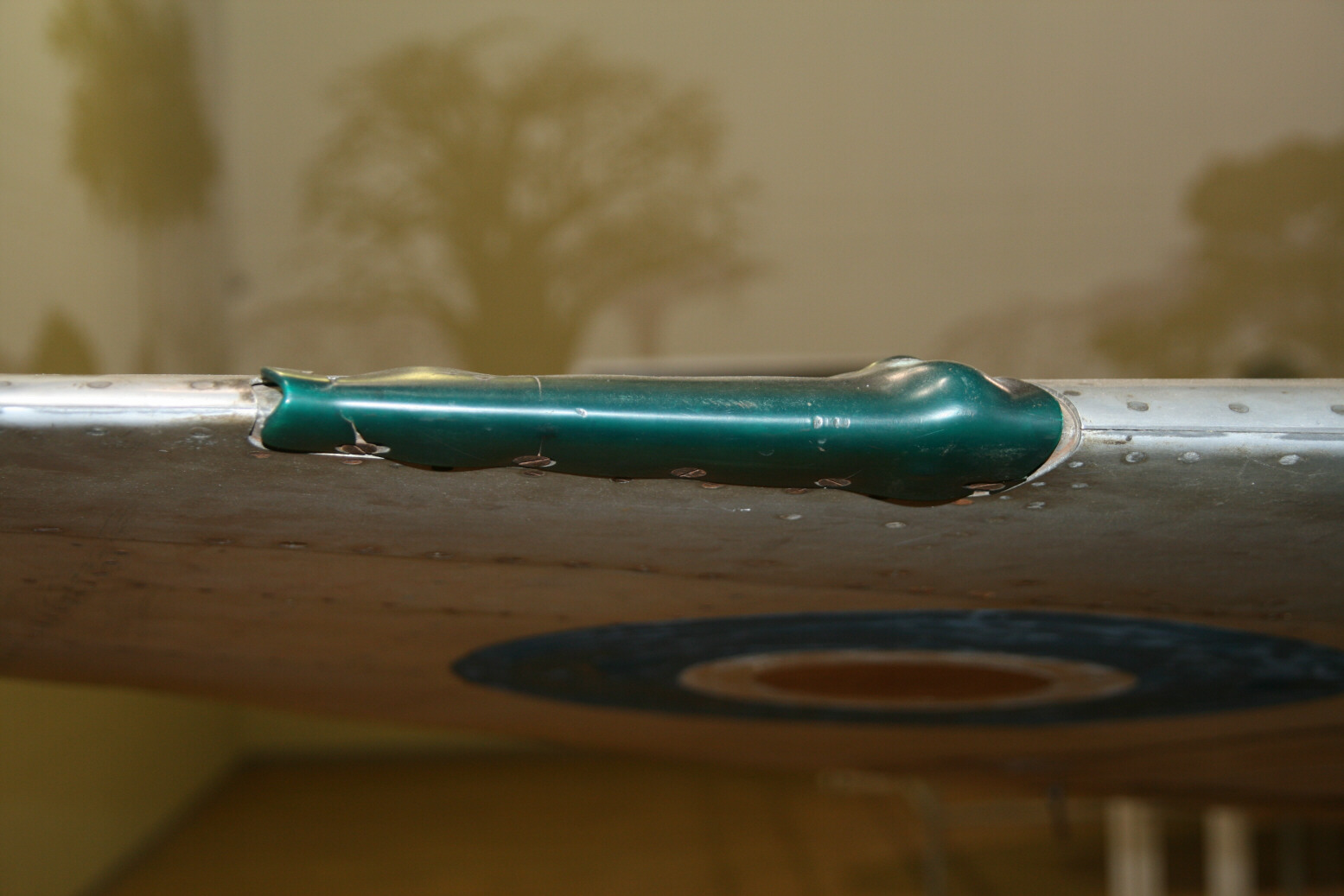
Photo 4 (below) shows the green navigation light at the leading edge of the starboard wing. The cover looks to be made of resin and by now has shrunk and is warped. The (red) cover on the port side is missing.
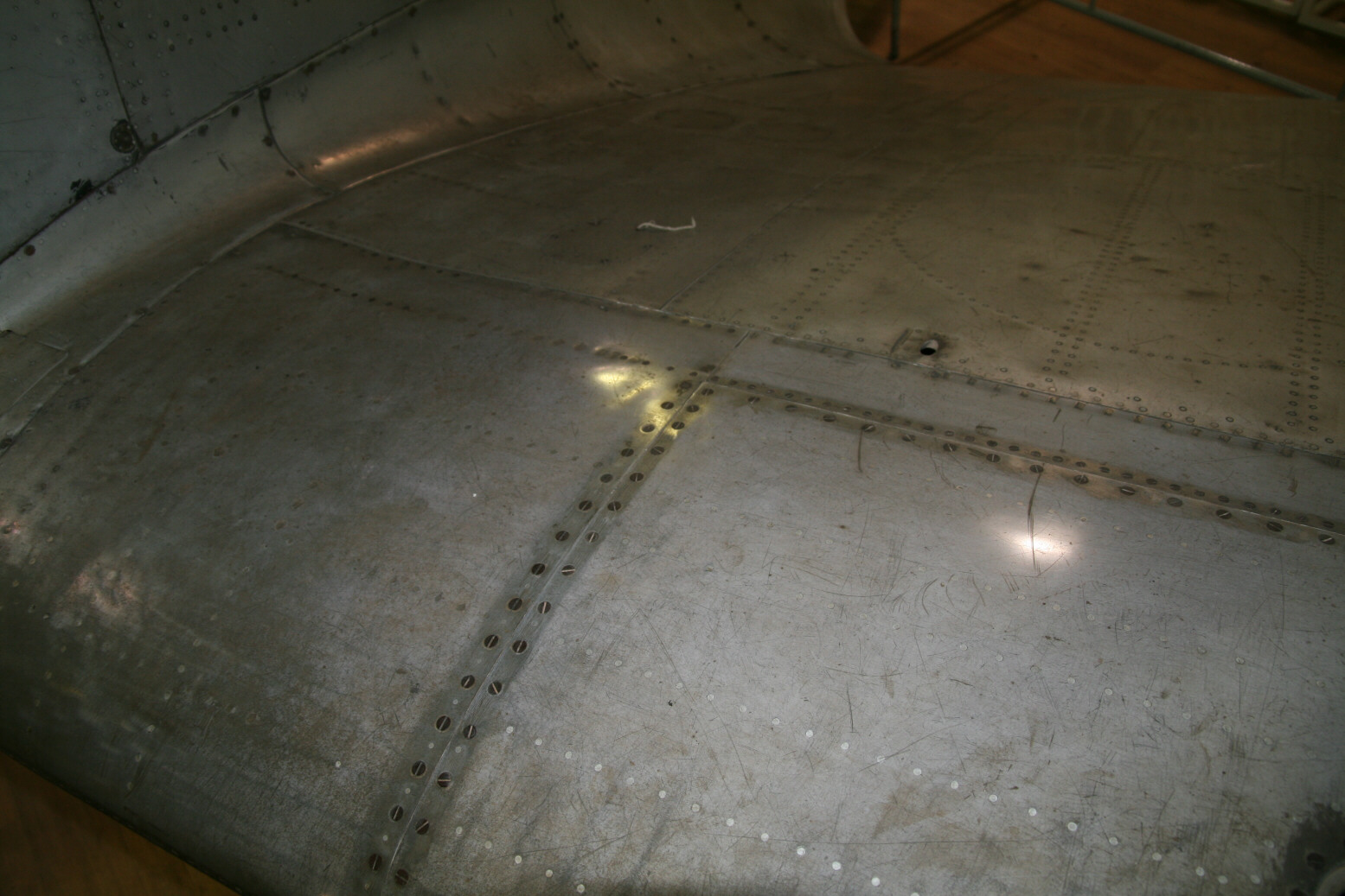
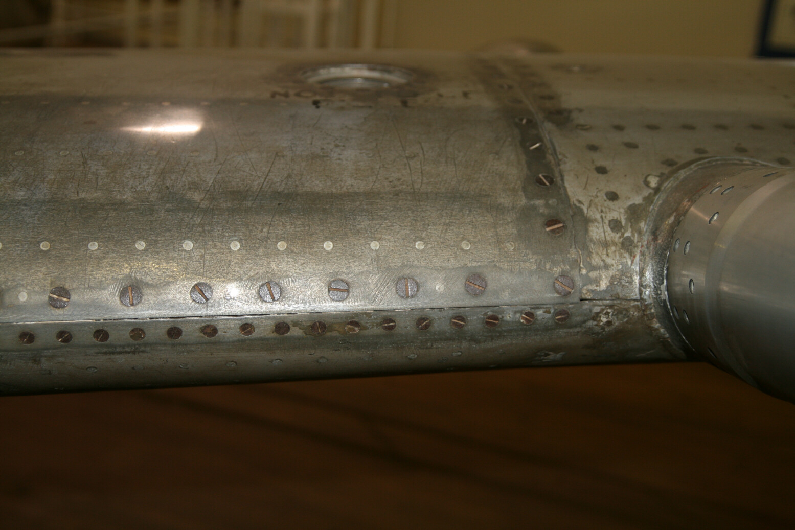
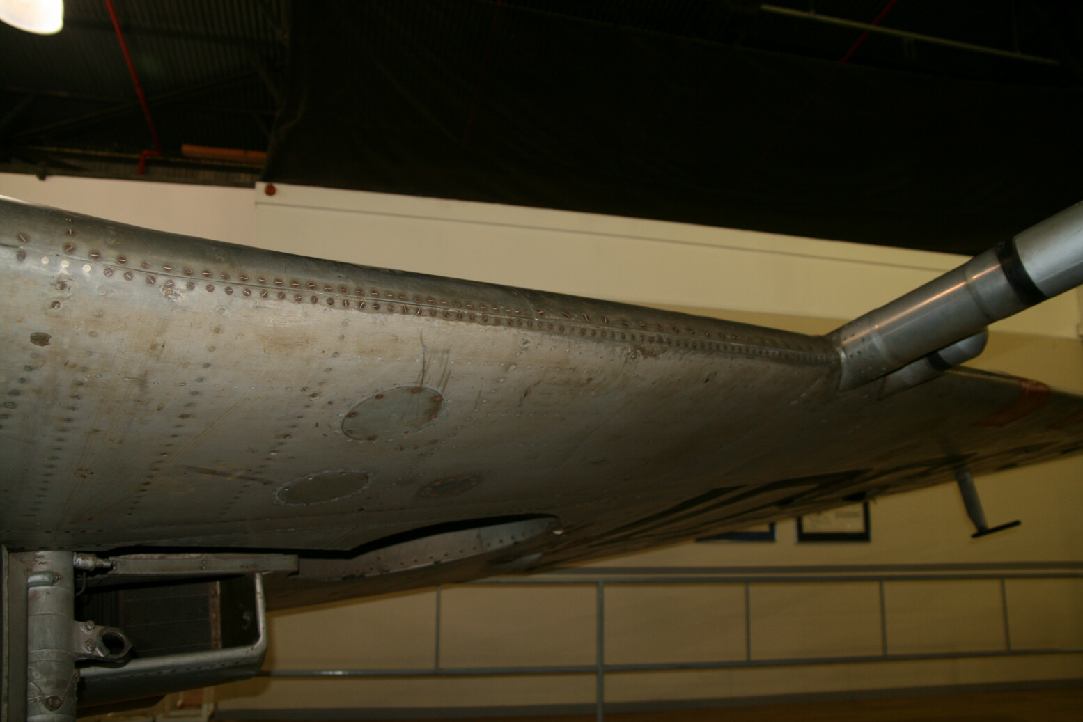
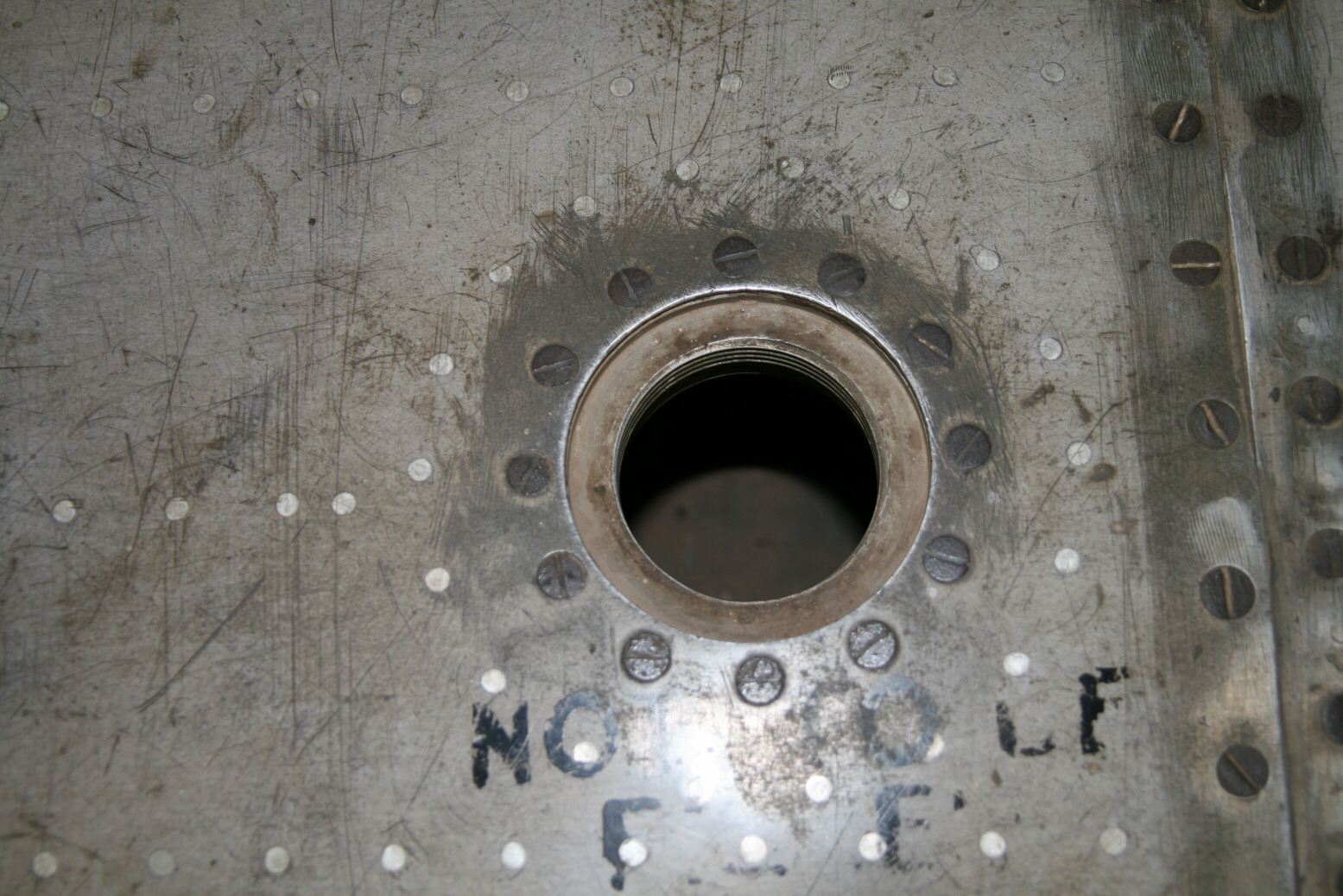
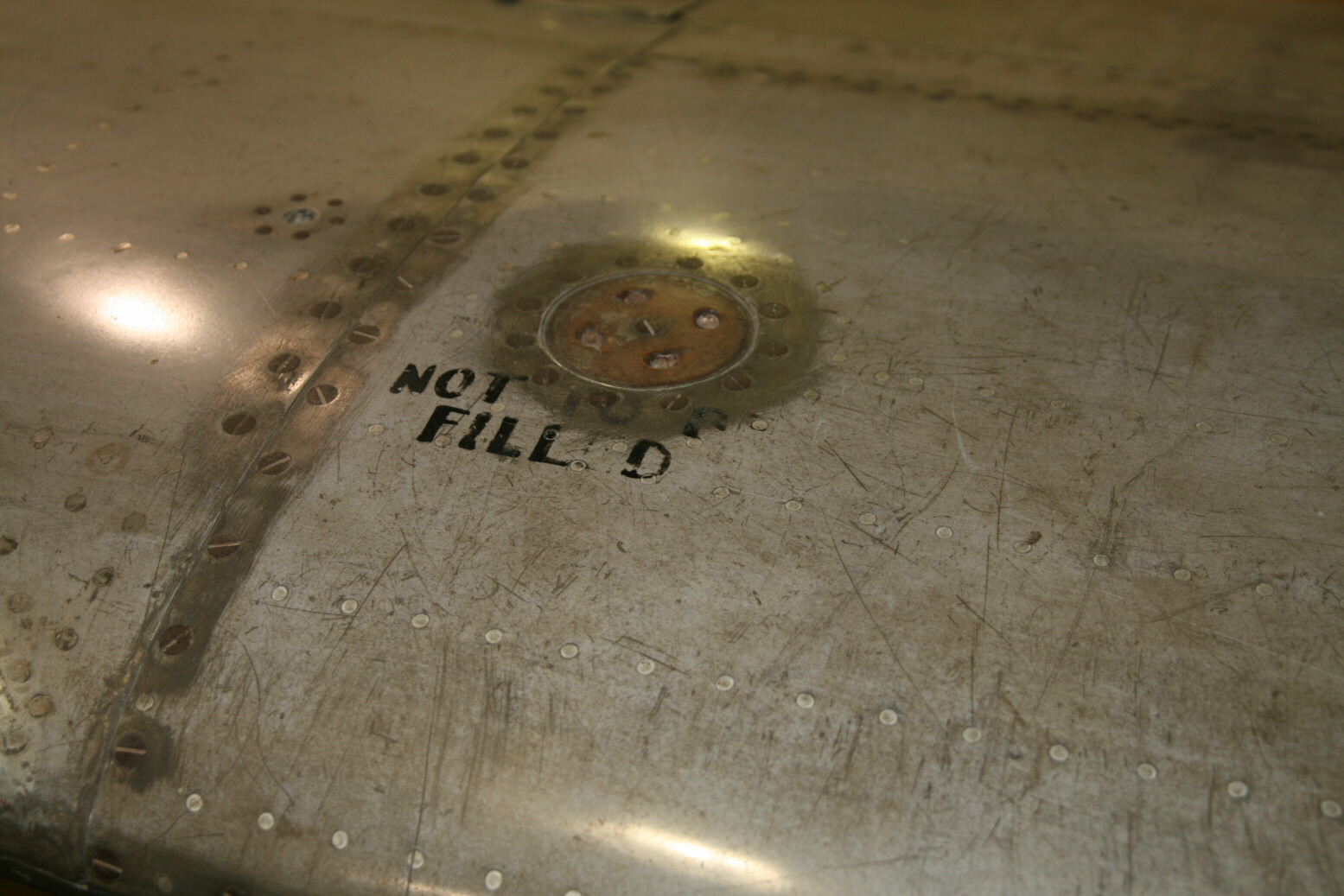
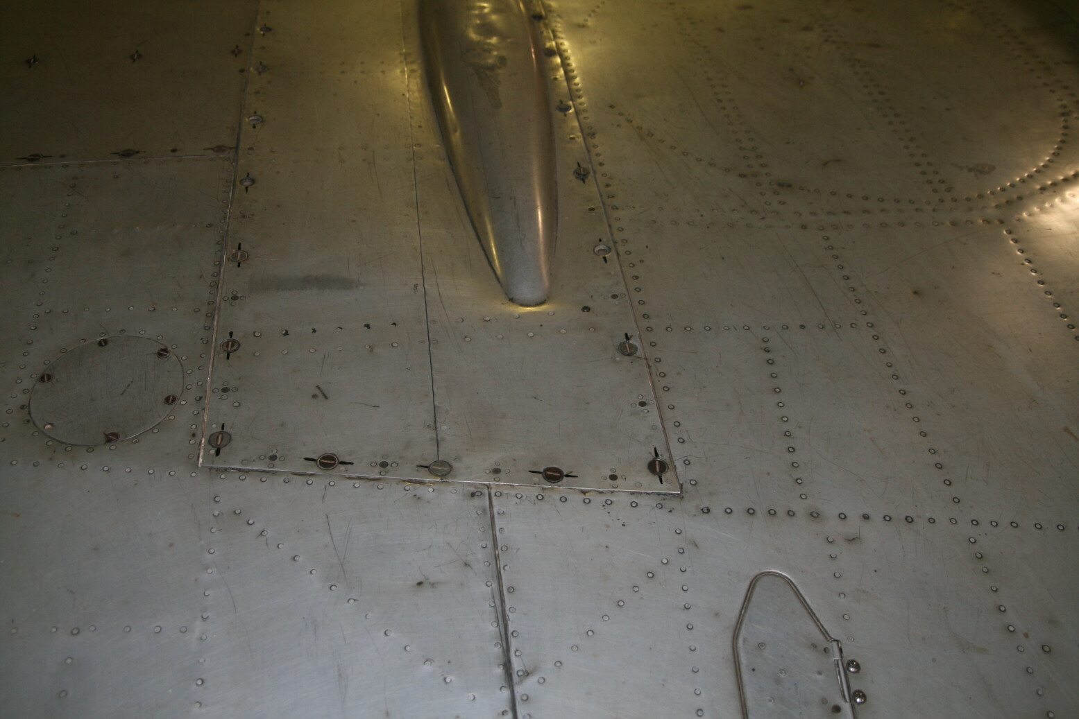
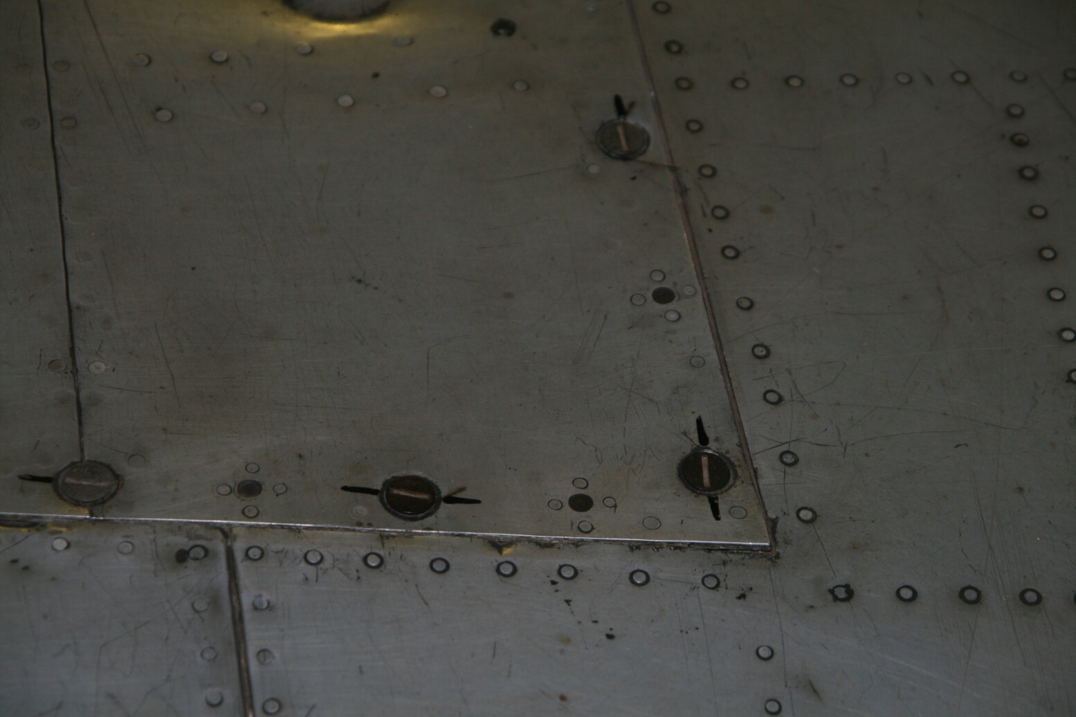
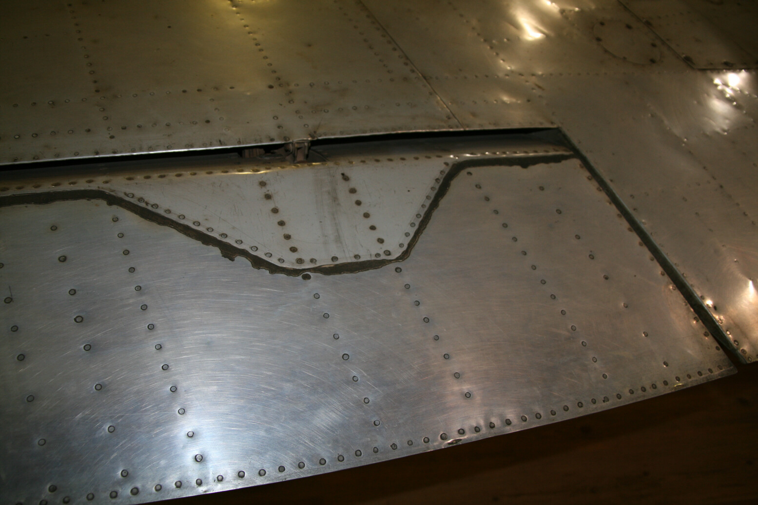
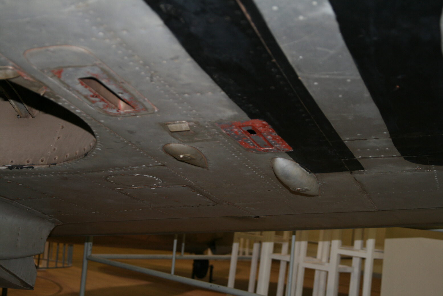
The 14 gallon leading-edge tanks were introduced with the Spitfire VII. The photographs of this particular Spitfire are very useful because of its bare-metal finish so nothing is hidden underneath paint. Photos 5 through 8 (below) show the fuel tank of the port wing. A number of things are noticeable. First of all, there are no panel lines at the bottom of the wing (photo 8), the undersurface is the same as for all Spitfires. A number of references (like Aero Detail 27) have this wrong. The panel on top is screwed down with brass screws which have been sanded to shape to give the wing a smooth surface. There is no gap visible between the top panel and the surrounding wing. Because of these features, on painted Spitfires the only thing you probably would see of these fuel tanks is the fuel filler cap. The text near the fuel filler caps states ‘not to be filled’. Presumably that was put there when the tanks were no longer in operation and is not original. The cap of the port wing is missing (photo 9), that of the starboard wing is still present (photo 10).

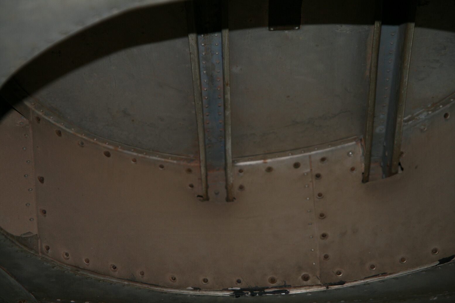
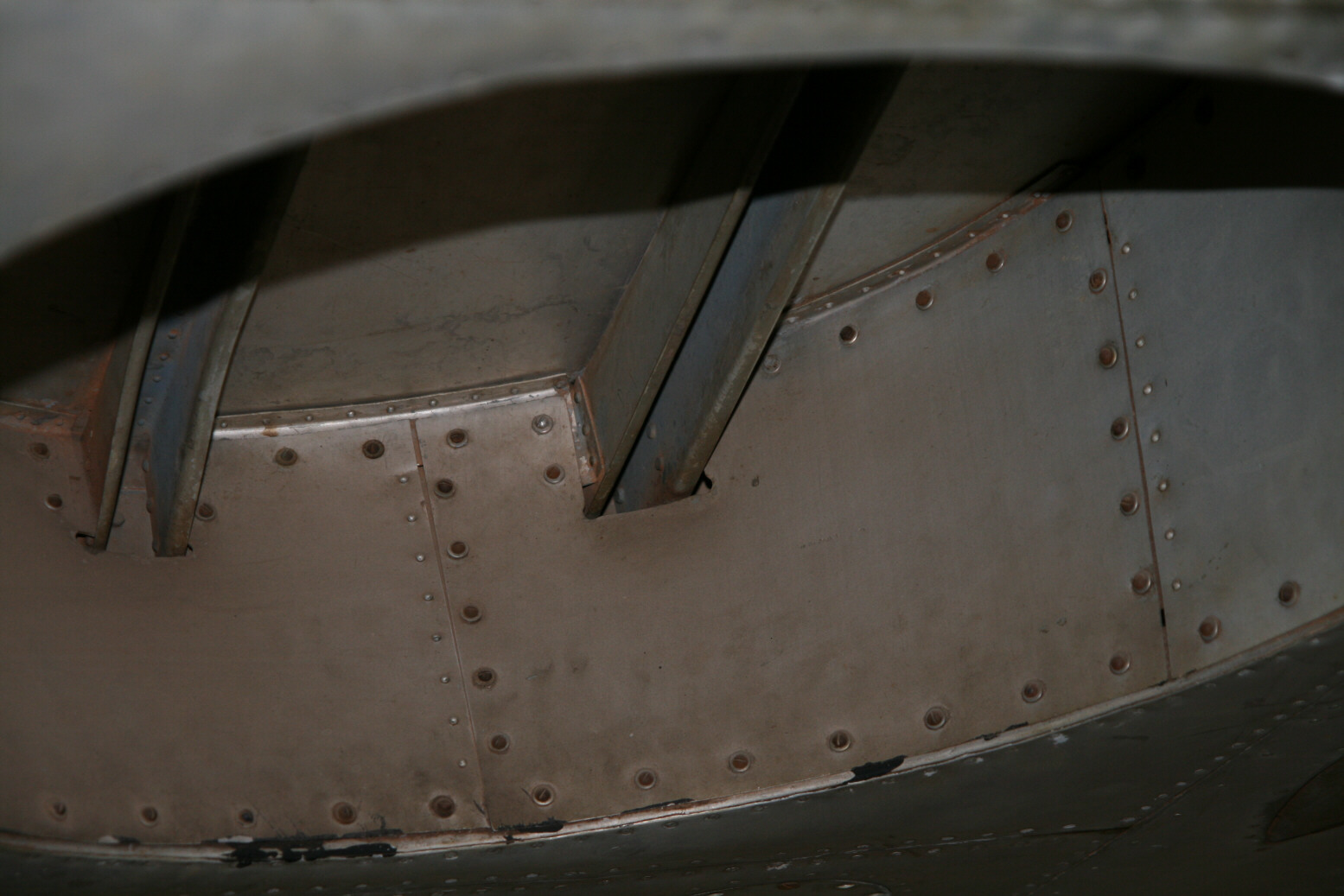
The reinforcements at the top of the wheel wells are quite high (photos 11 and 12, below), roughly as high as they are wide.
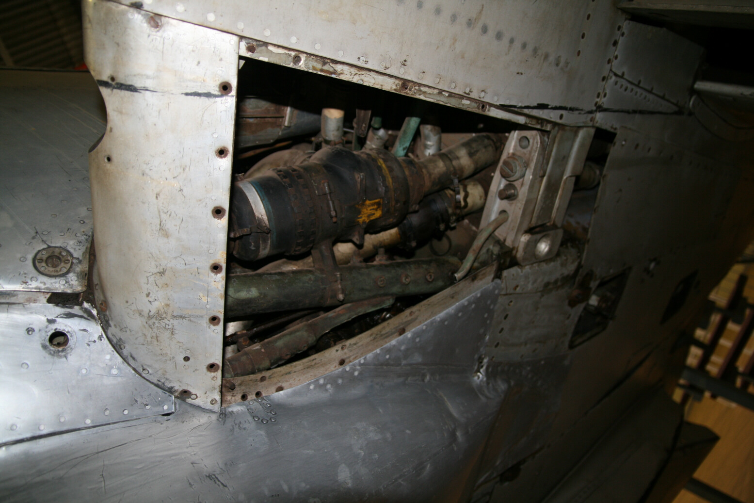
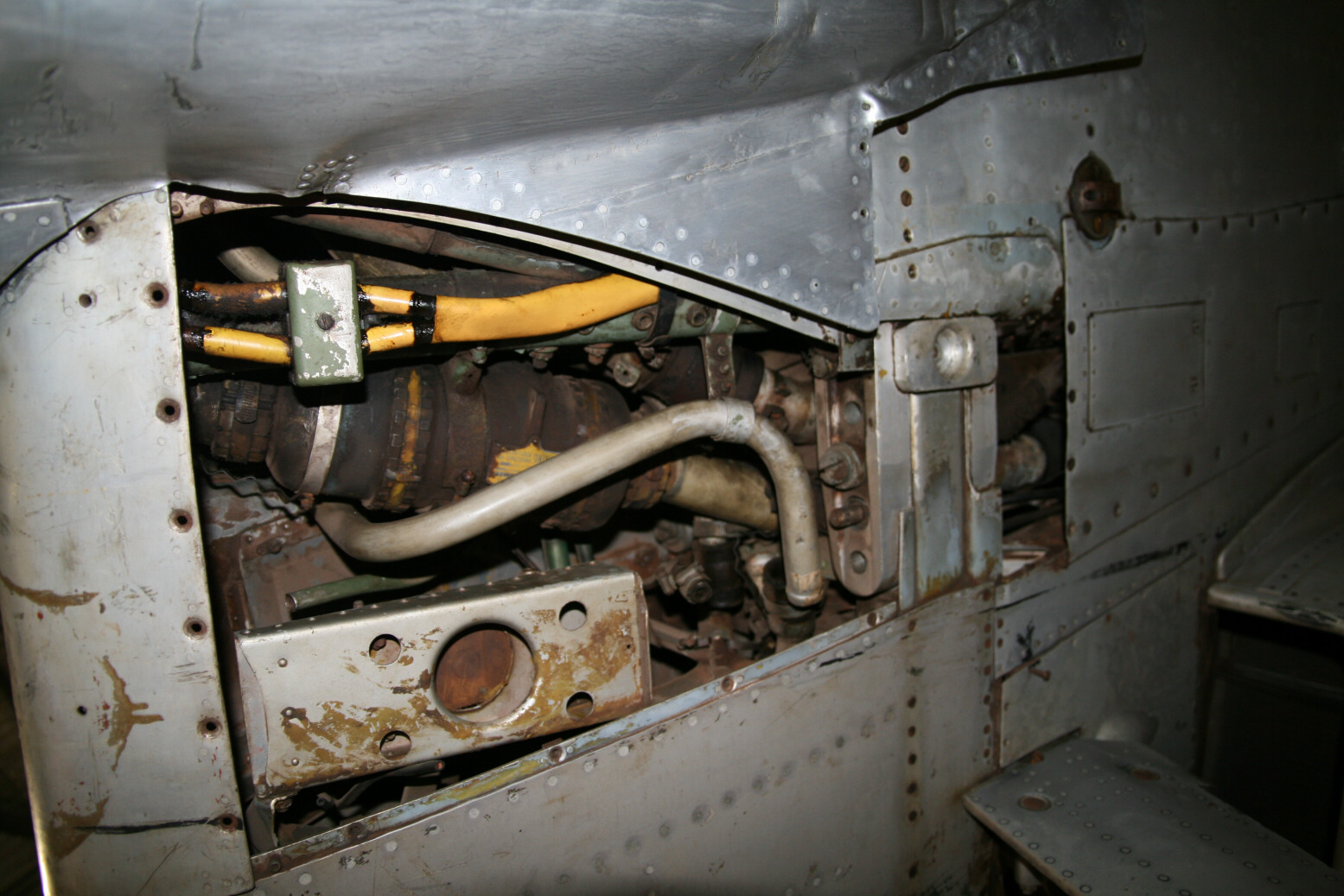
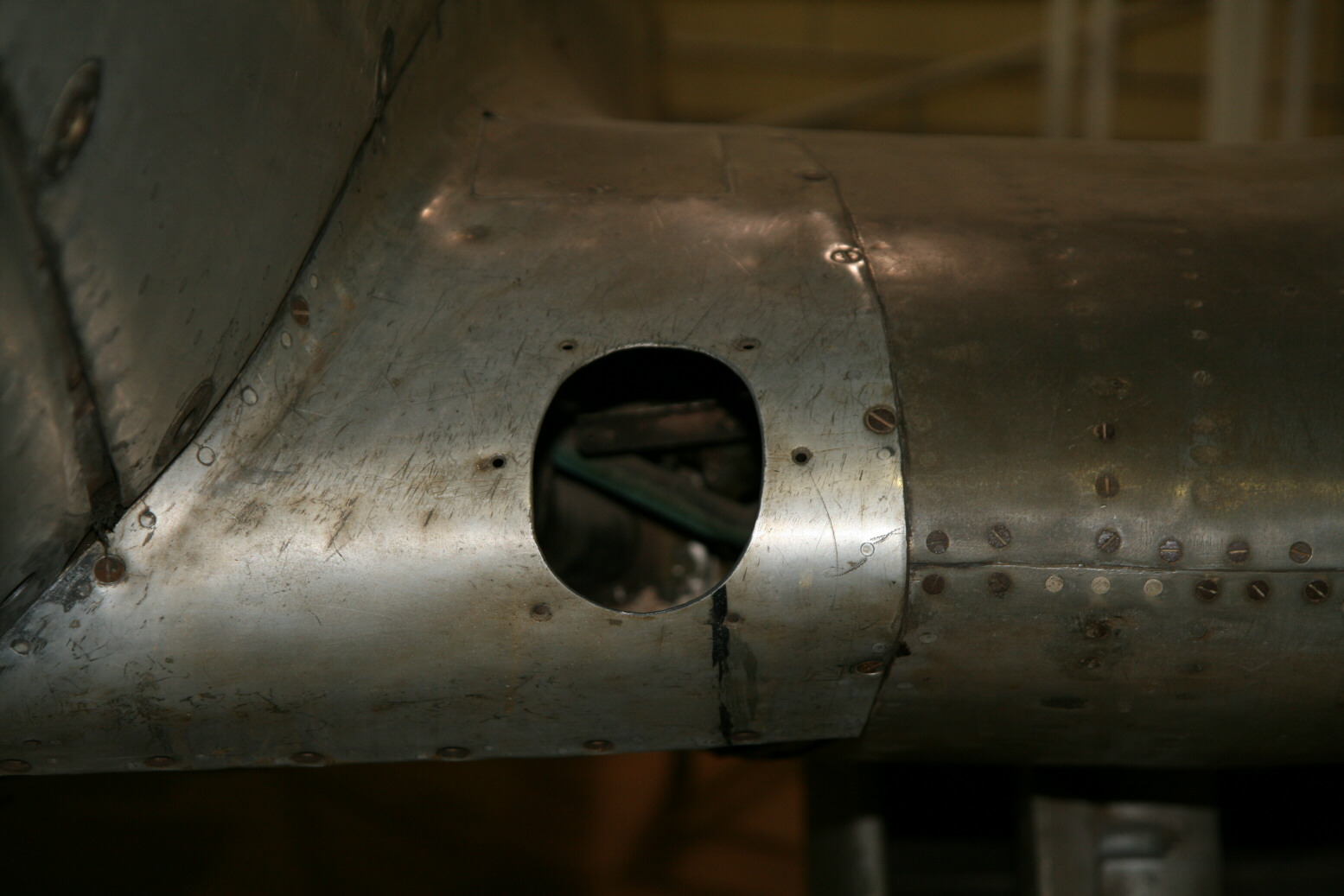
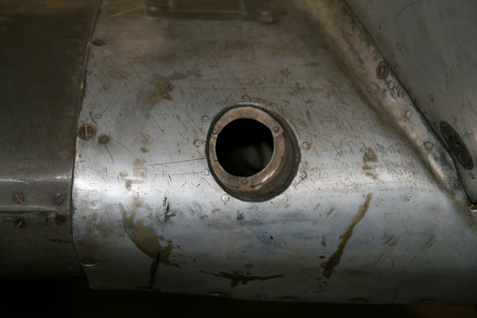
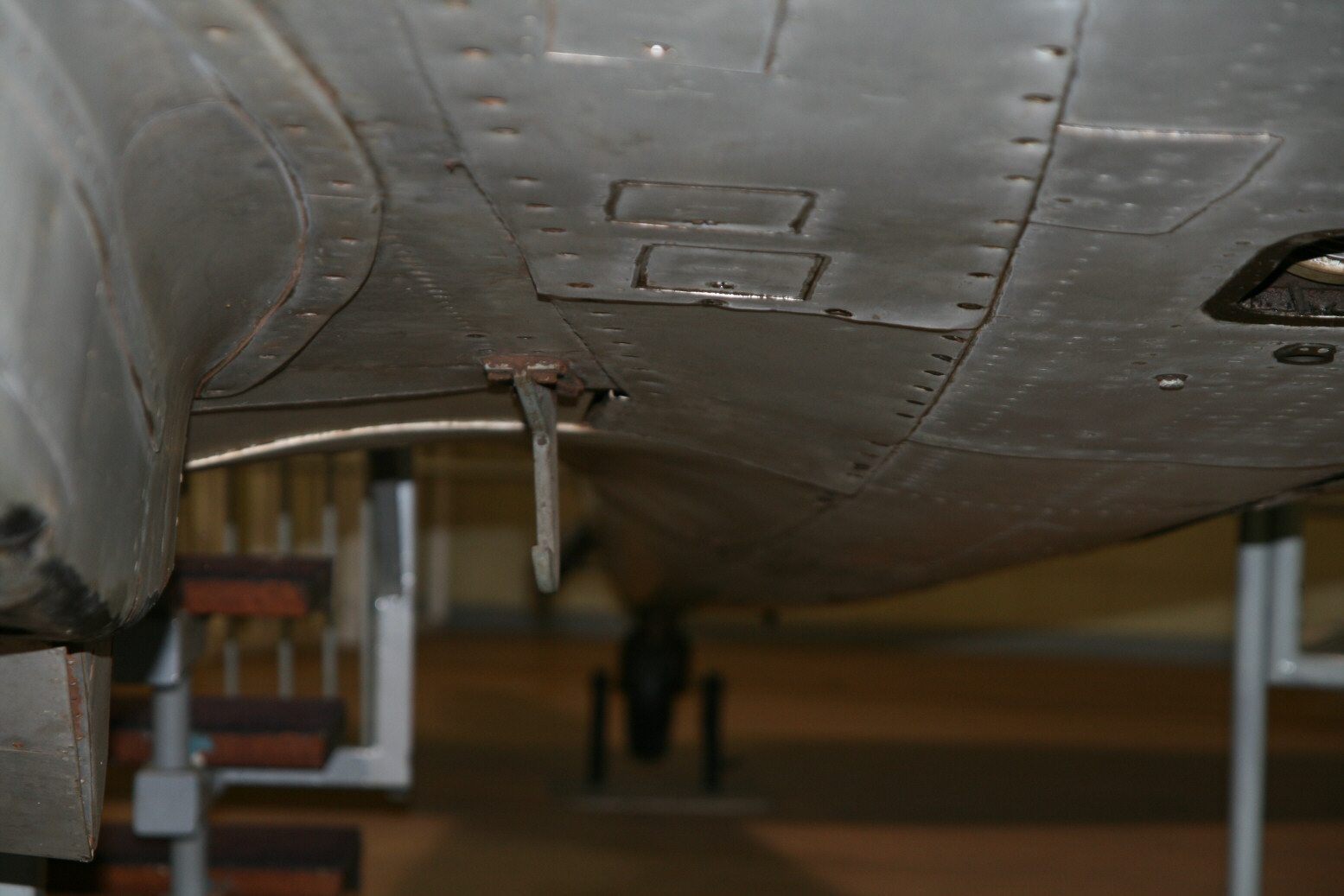
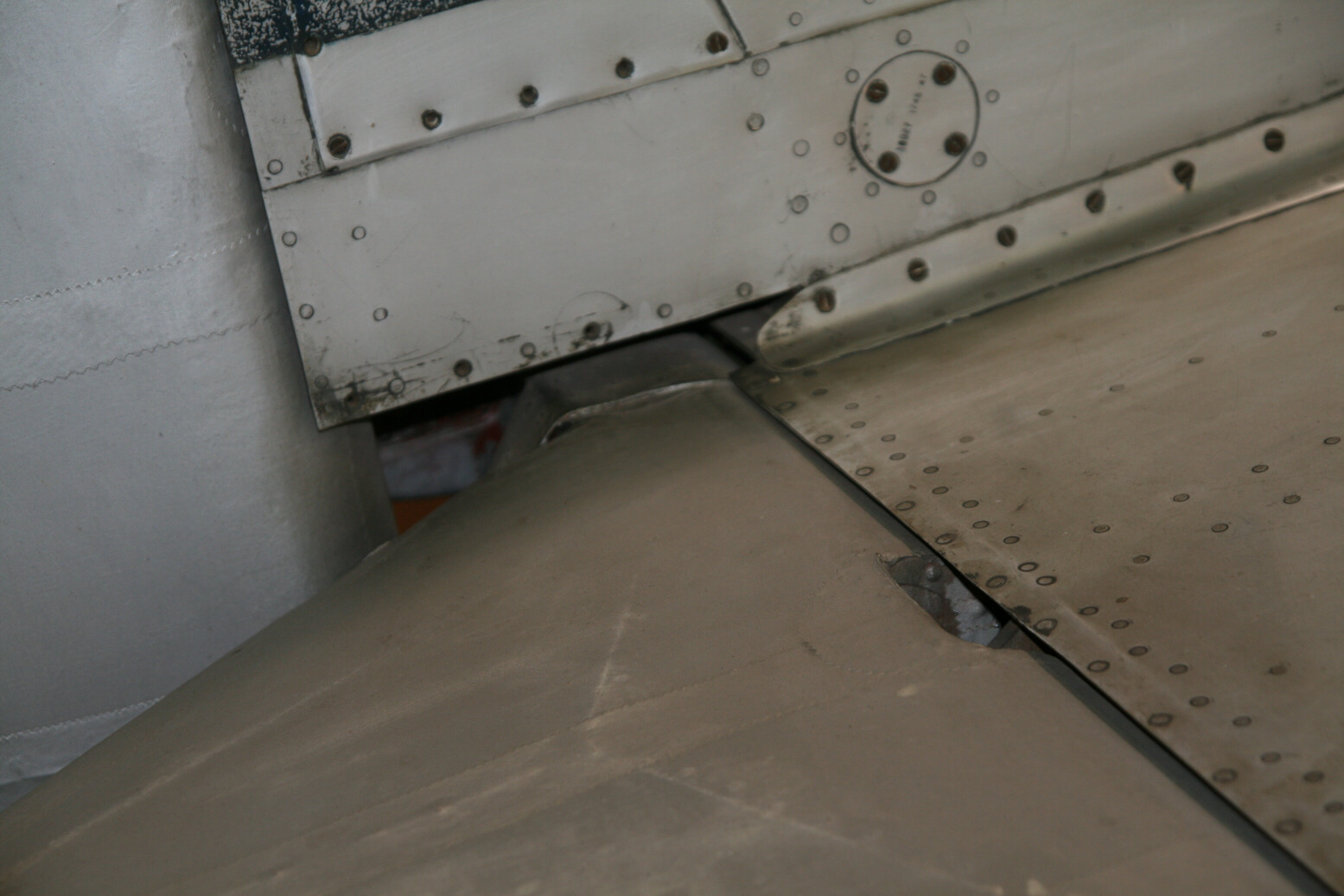
The forward parts of the undersurface wing fillets are missing, giving us a view of the insides. On the port side (photo 13, below) we see the plumbing of the cooling system. I am guessing that the dark green bar near the bottom (with the three circular items) is the lower engine bearer. The connection of the wing spar to the fuselage is not as it should be as there is only one bolt (plus an unidentifiable pin and a pipe) in place while there should be four. The glistening dimple underneath the wing spar is the jacking point underneath the wing. On the starboard side (photos 14 and 15, below) we again see the engine bearer and cooling pipe. Also here the connection between wing and fuselage has only one bolt. The yellow sleeves must contain electrical wiring. In view of its position the rectangular item on the lower left could be related to the gun camera. There are holes in the wing leading edges near the fuselage. The one on the port side (photo 16, below) was probably for fuel cooling (currently there is nothing behind it) while that on the starboard side (photo 17, below) was for the gun camera. Notice also that the filets are fixed in place by a mixture of rivets and screws. The use of screws could have been a change from the original situation if the Spitfire was used as an instructional air frame.

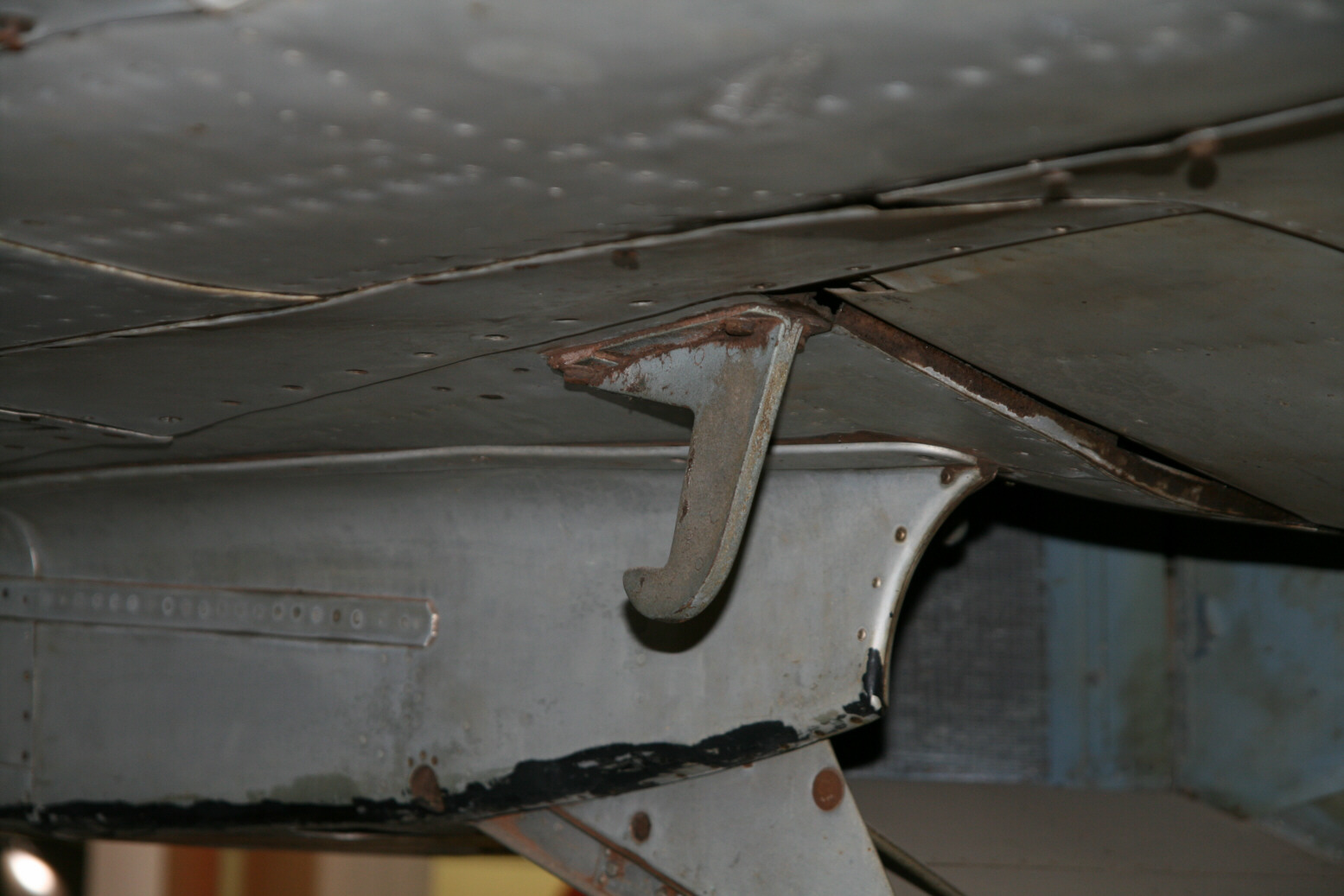

Below the wing are hooks (photos 16 through 20, above) for the drop tank (these were not intended to support the tank but ensured that when it was dropped the front would fall first so the whole tank would drop away and could not hit the fuselage or tail wheel). Most of the reference material I have isn’t very clear with regard to its position. The pictures show that is almost against the edge of the wing fillet, while its back is aligned with the back edge of the wing (immediately behind is the inner flap).
Due to difficult lighting and the closed canopy (causing bad reflections of the photo flash) there isn’t much visible inside the cockpit. What is noticeable is that the reinforcement bar between the fuselage near the top of the hind canopy is rather thin and circular. The frame visible in photo 21 (below) is the frame (no. 11) directly behind the cockpit, with the tail of the airplane towards the right.

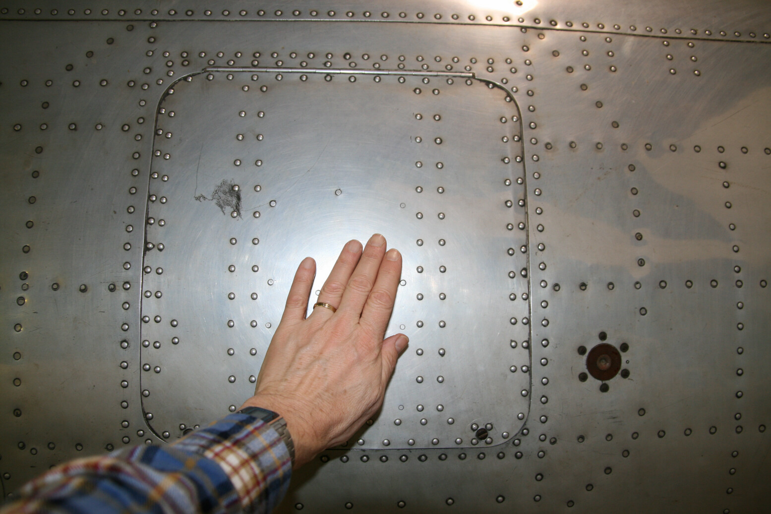
The radio hatch (photo 22, below) is far smaller than what I thought it would be. You can judge the size from my hand. The brown circular item with the six rivets around it is the insulator for the IFF aerial. Photos 22 and 23-24 (below) also show that the fuselage plates do no abut but overlap, with just a single row of rivets. Some – but not all – of the rivets are flush.
Photos 25 and 26 (below) show how the panels over the cannon are fixed with large screws, with lines on the panels indicating the direction of the screws.
The metal-covered ailerons (photo 27, below) consist of two parts, with some kind of sealant in between (the dirty, dark material).
The radiator housing (port side, photo 28, below) has a reinforcement strake along its side, plus a noticeable dent at the bottom on one side.
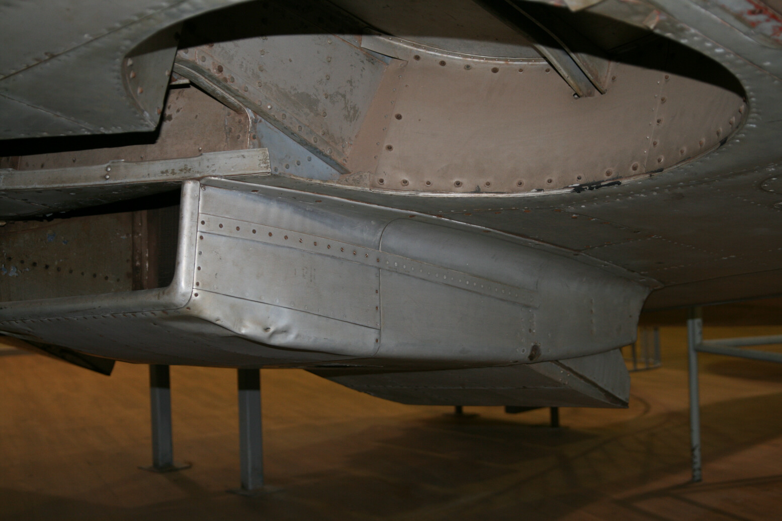
Photo 29 (port wing, below) shows the ejector chute for the cannon, the dummy plate for the absent .5" gun and the bulges. The black-painted areas are part of the serial number painted below the wing (see also photo 8).
Finally photo 30 (below) shows a detail of the tail. At lower bottom is the starboard elevator, left is the rudder. What is noticeable is that the backside of the fuselage/fin has a pronounced gap for the connector between the two elevators. Most kits have this filled but it looks like it should just be open (or there is a fillet missing here).
© Max Otten 2015
This article created on Friday, April 03 2015; Last modified on Thursday, January 04 2018