
De Havilland Mosquito B.35 at the RAF Museum, Hendon
Photos By Max Otten
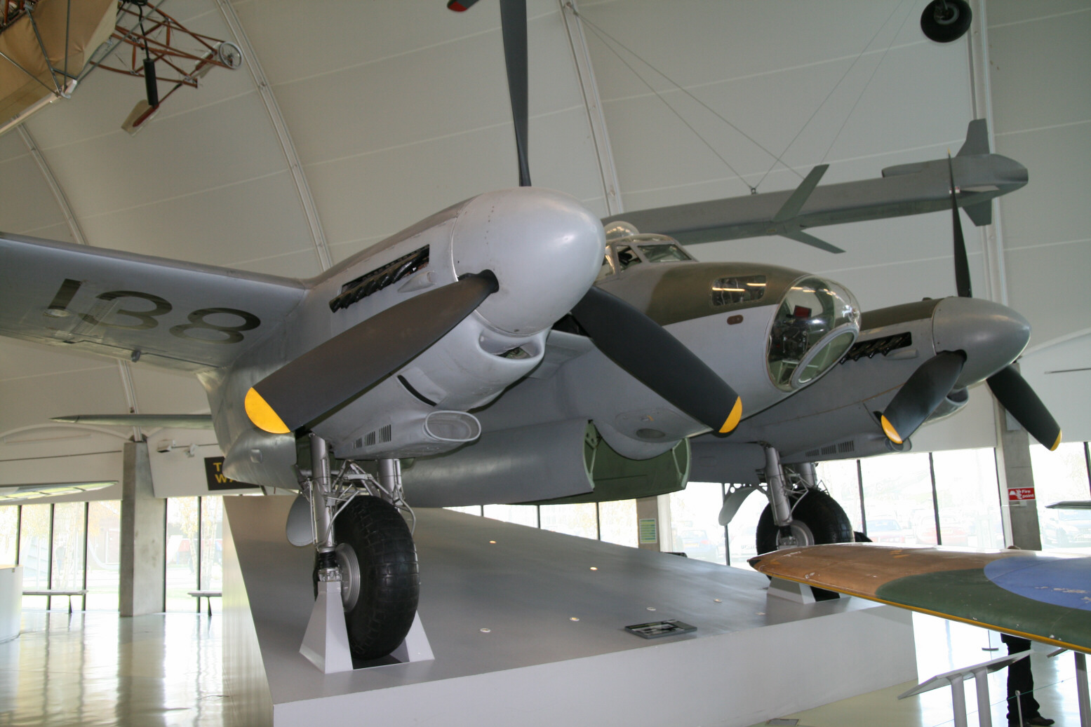
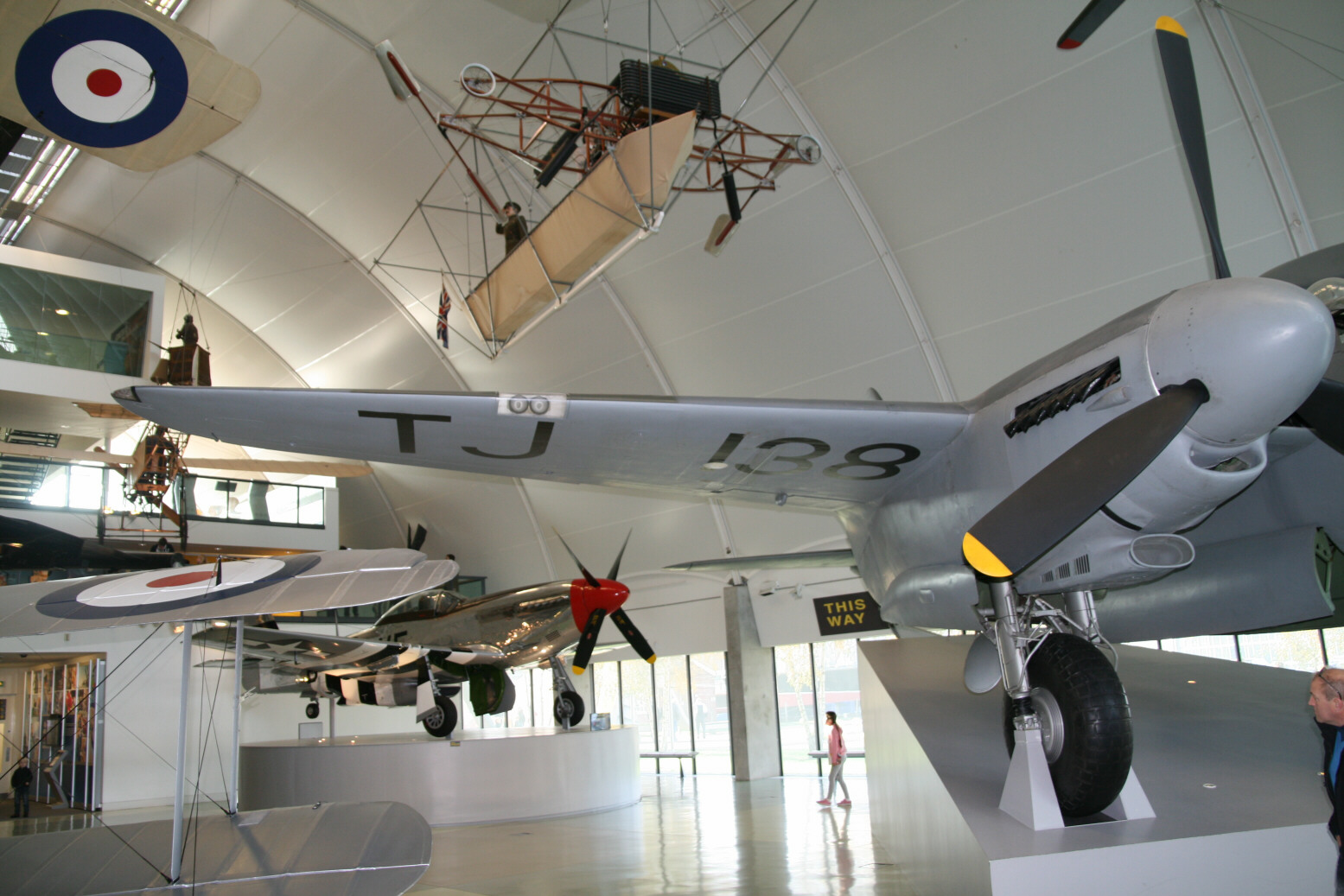
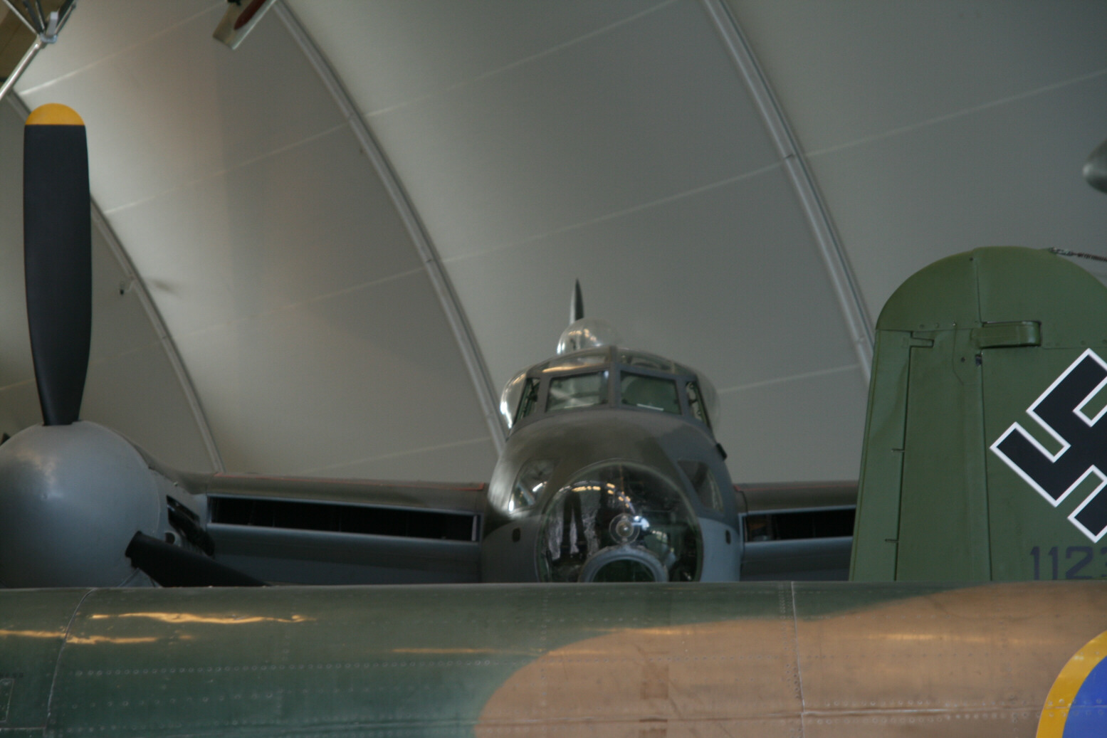
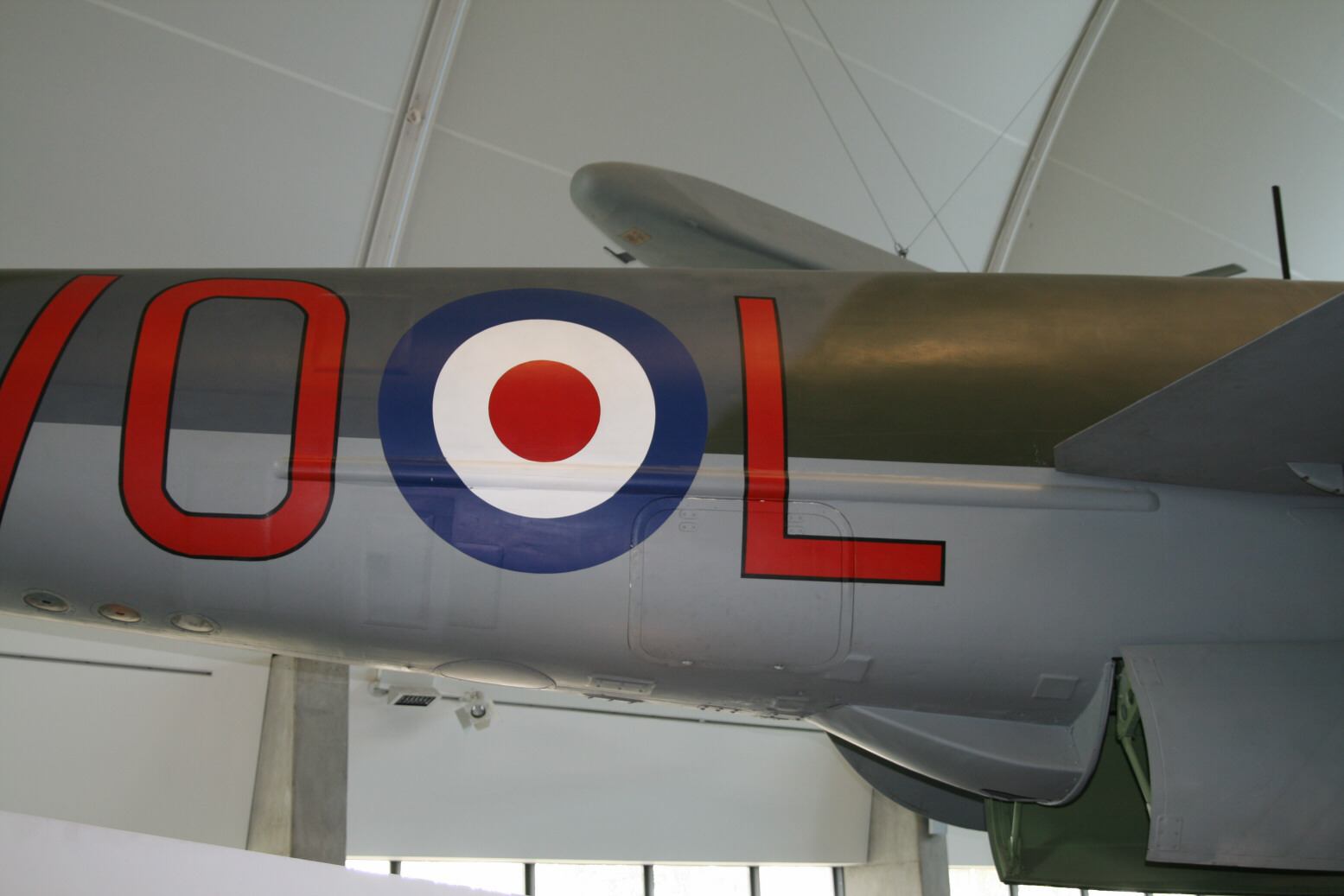
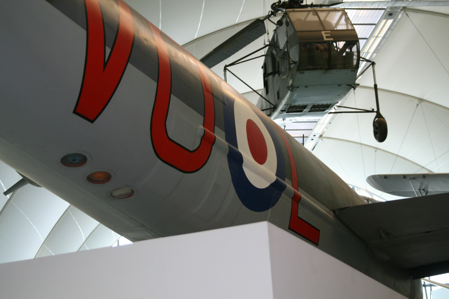
The pictures were taken at the RAF Museum at Hendon (London). The Mosquito there is a B.35, serial number TJ138. It is situated on a platform that allows a very good view into the main undercarriage bays, less into the bomb bay, while the cockpit is completely inaccessible because it is very high up. Picture 1 shows a side view of the Mosquito on its platform. (Tip: hover over the image thumbnails to get a tooltip showing the image number.)
Lights
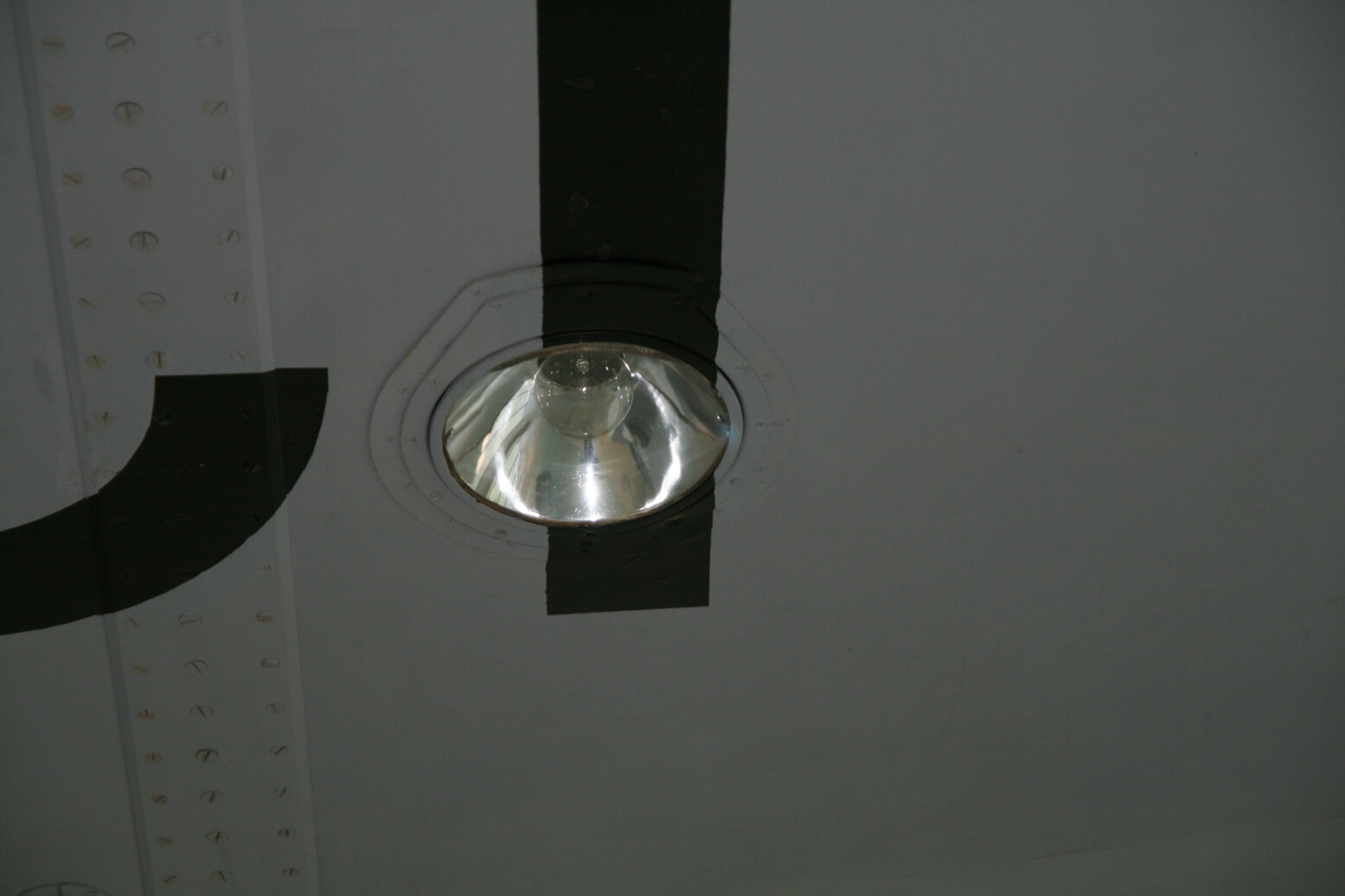
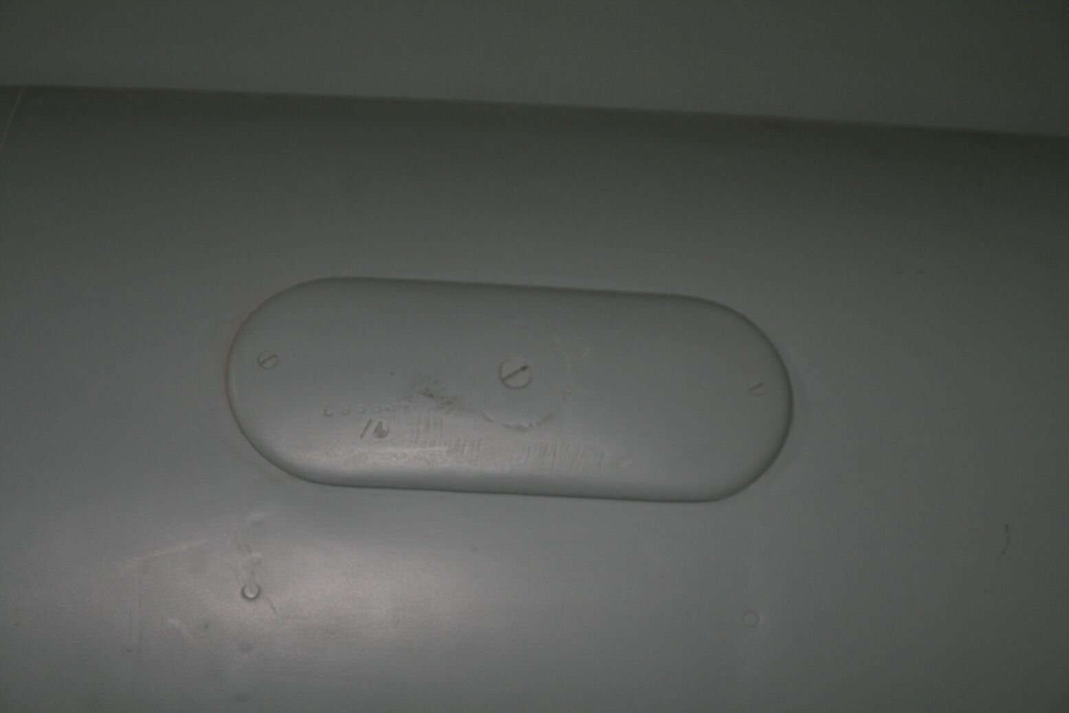
This Mosquito has the standard Mosquito landing lights in the bottom of both wings, outboard of the engine nacelles. The face of the lights is flat. Picture 2 shows the landing light in the port wing. The black bands are part of the serial number painted on the wing bottom.
In addition, it has a set of two landing lights in the leading edge of the starboard wing (only!) Picture 3 shows this landing light in detail, while picture 4 shows its location in the whole wing. The wing tip navigation lights have clear Perspex faces. It is the light bulb that has the color, red as in picture 5 on the port wing tip.

Engines
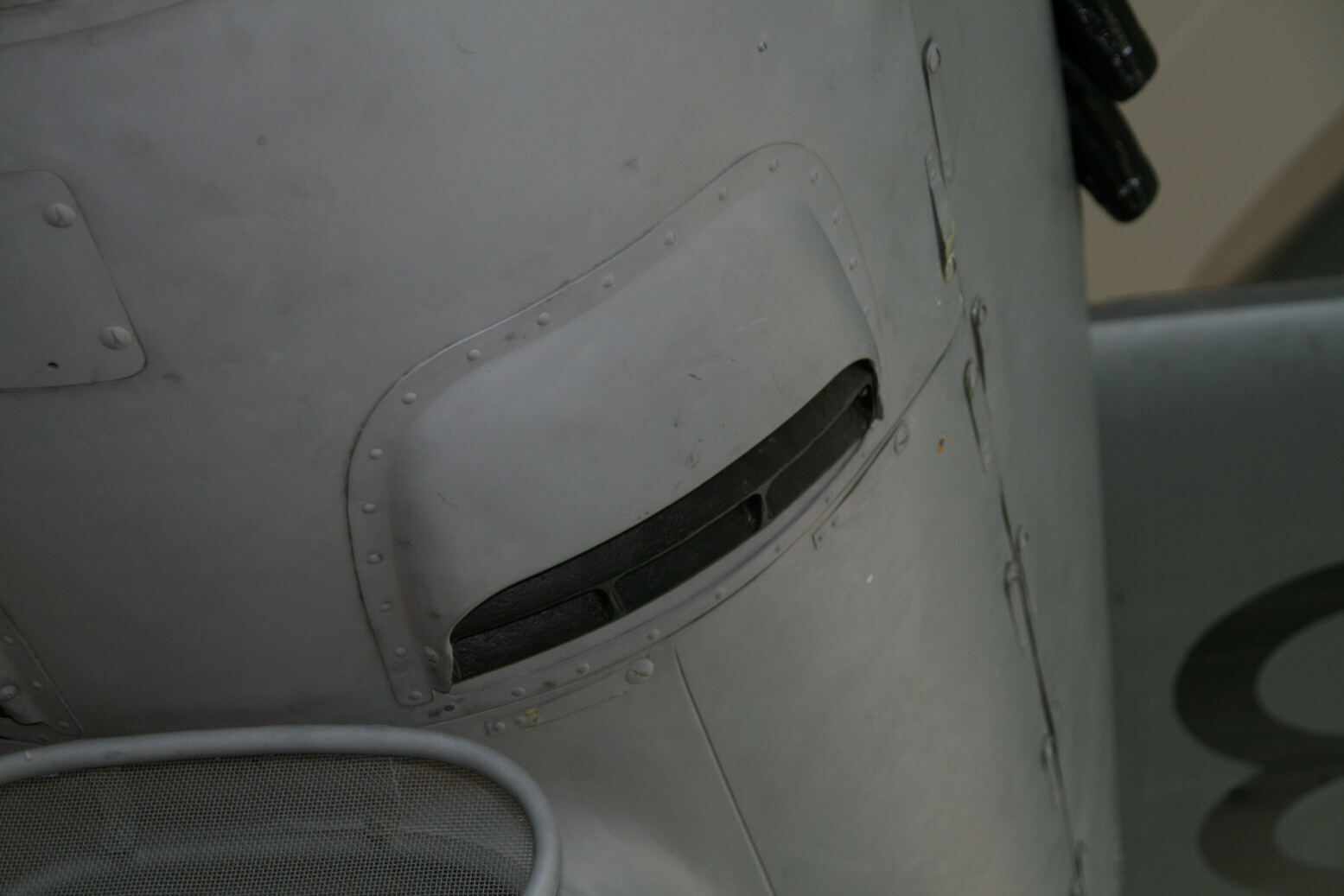
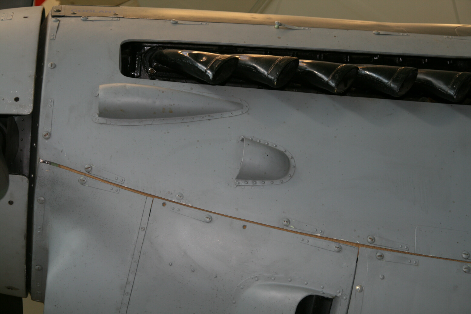
The engines are two-stage supercharged. On either side of each nacelle they have the supercharger intercooler vents. These consist of a bulge with two slits at the back. The hind slit has two reinforcements running across. Pictures 6 and 7 show the vent on the outboard of the port nacelle. Picture 8 shows the vents on the starboard nacelle, as well as the air intake underneath the spinner, its mesh guard and louvers at the end. Picture 9 shows a close-up of the mesh guard (port nacelle). Pictures 10 and 11 shows the intercooler vent again, this time the outboard starboard one.

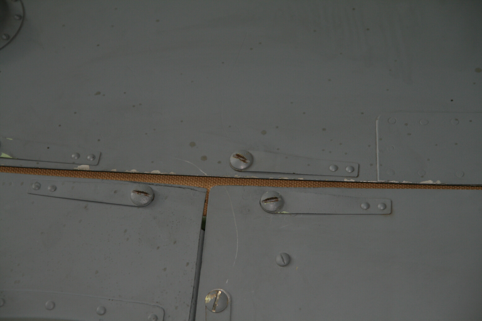
The engine cowlings are held in position by fasteners that are attached to metal strips that in turn are connected to the panel by two rivets as shown in picture 12 (below).
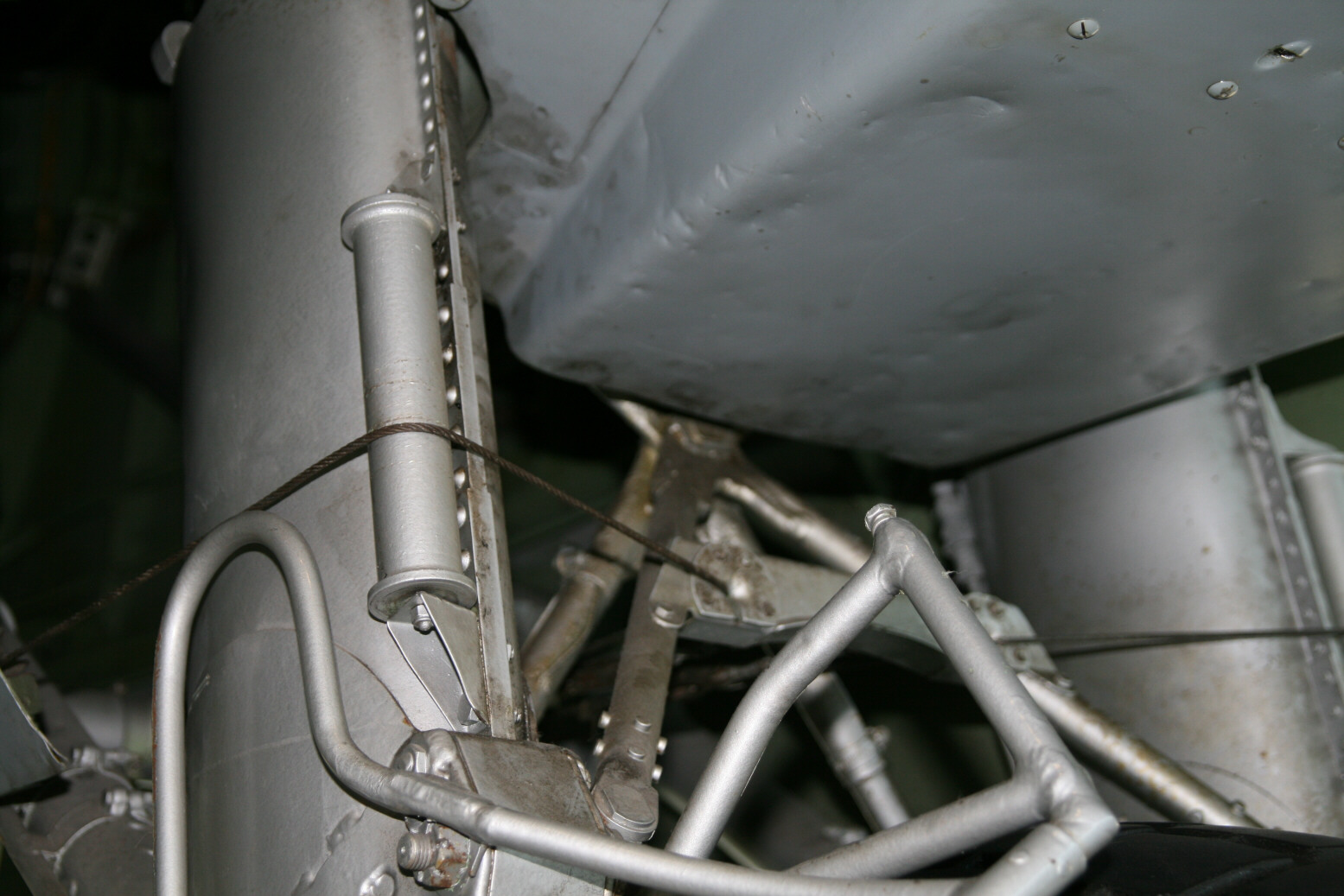
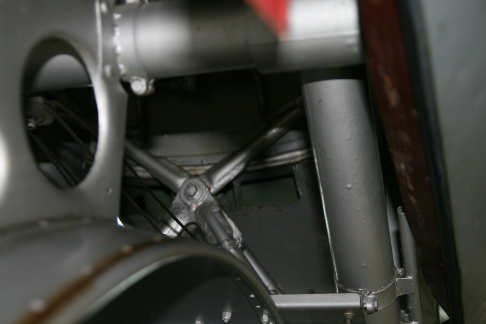
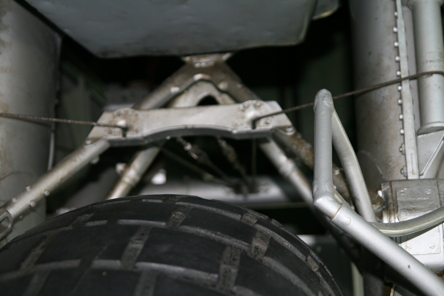
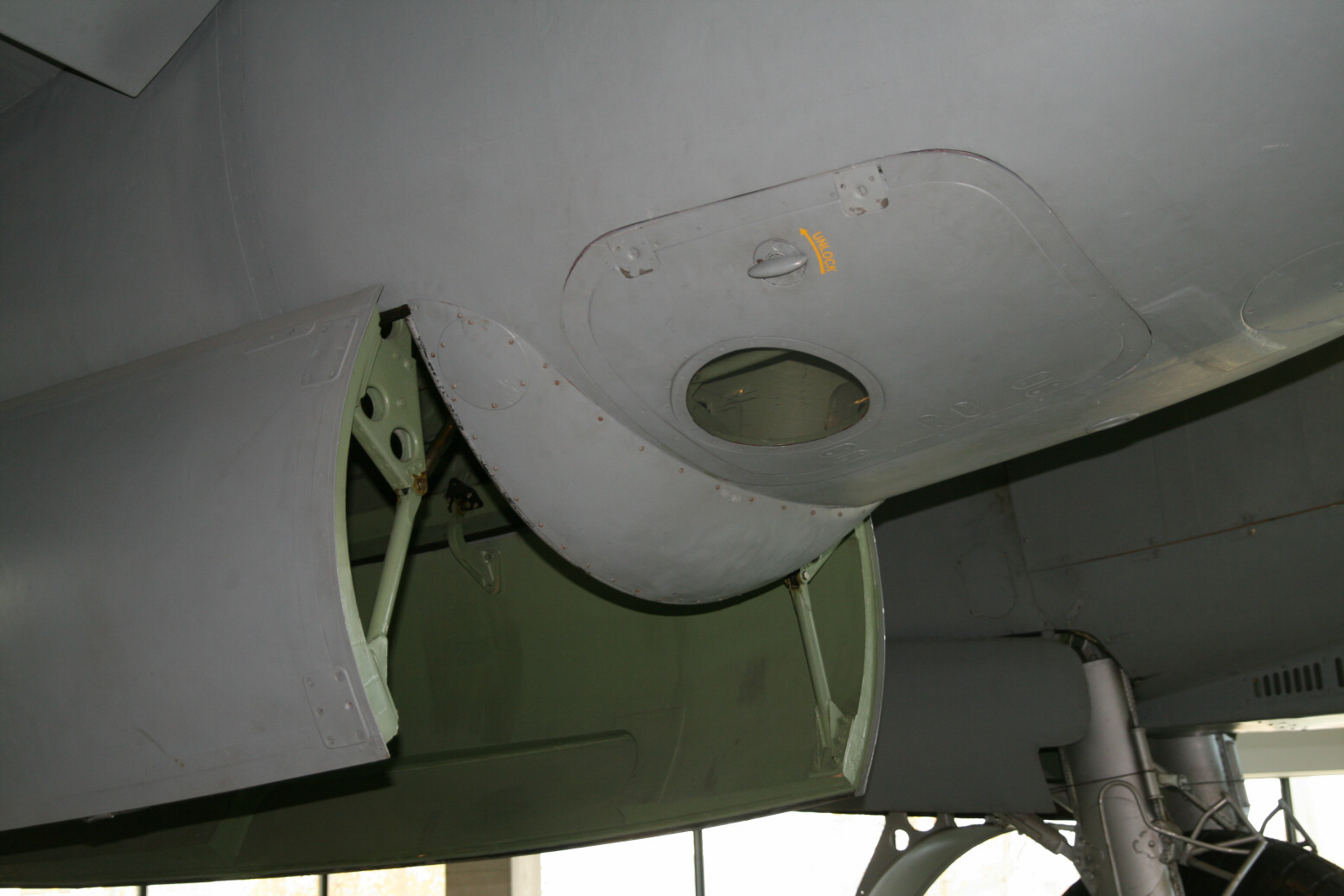
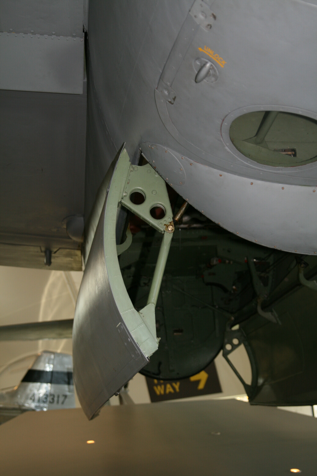
Picture 13 shows a side view of the air intake louvers. The end of the air intake is not flush with the bottom of the nacelle where it ends at the main undercarriage doors but is lower (picture 14). Picture 15 shows the end from the back (though difficult to see behind the undercarriage brace). Partly hidden behind the cross-brace is the rim of the bay (silver). Below this is the end of the air intake. It is green on the inside and has two vertical reinforcements (one is well visible to the right of the centre of the cross, part of the one to left is just visible behind the cross).
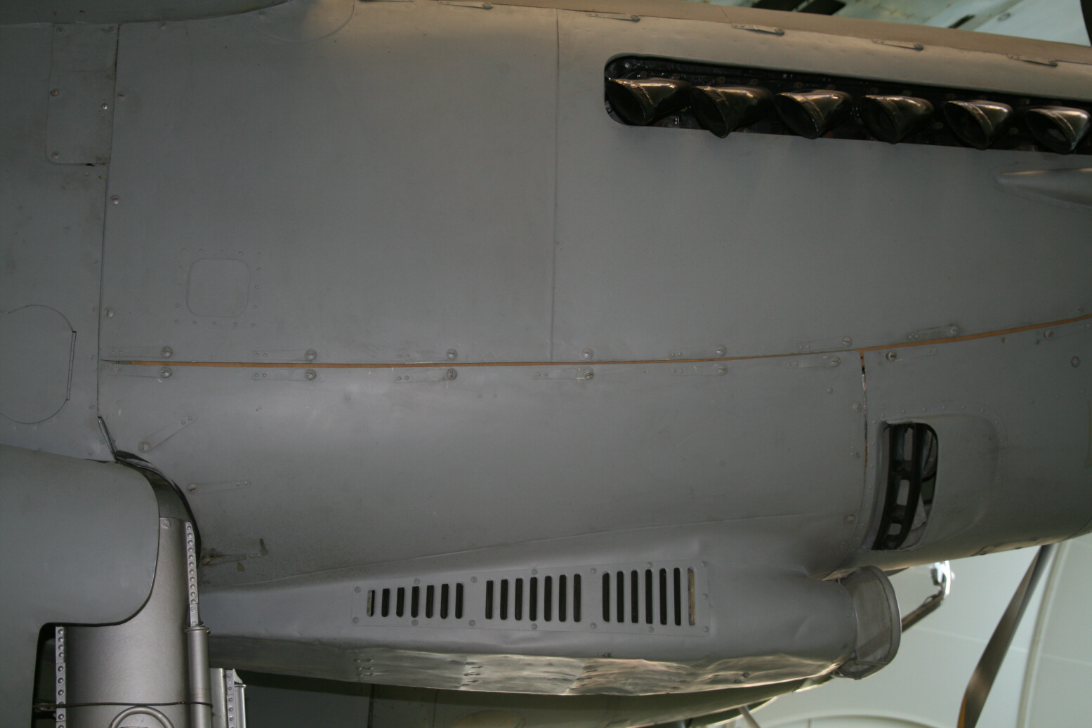
Picture 16 (below) shows a close-up of the other intakes. The front-most one occurs on either side of the nacelles and is the sparking plug cooling vent. The smaller one only occurs on the port side of the nacelles. In one of my reference books it is quoted as a cold-air intake (but not for what – there often is a fuel pump cooling duct but that is normally further back and lower).
Main Undercarriage
The undercarriage bays of the Mosquito are not handed (that means port and starboard are pretty much the same). The kits I have seen so far have this wrong (or they do not have sufficiently detail to tell). The roof of the bay is the top of the wing so it is curved from front to back. In one of the picture there is a hole in the top and there you can see that the top surface of the wing is several centimetres thick. One distinction between the port and starboard bays is the top of the back end which runs at an angle. This must be the rear wing spar.
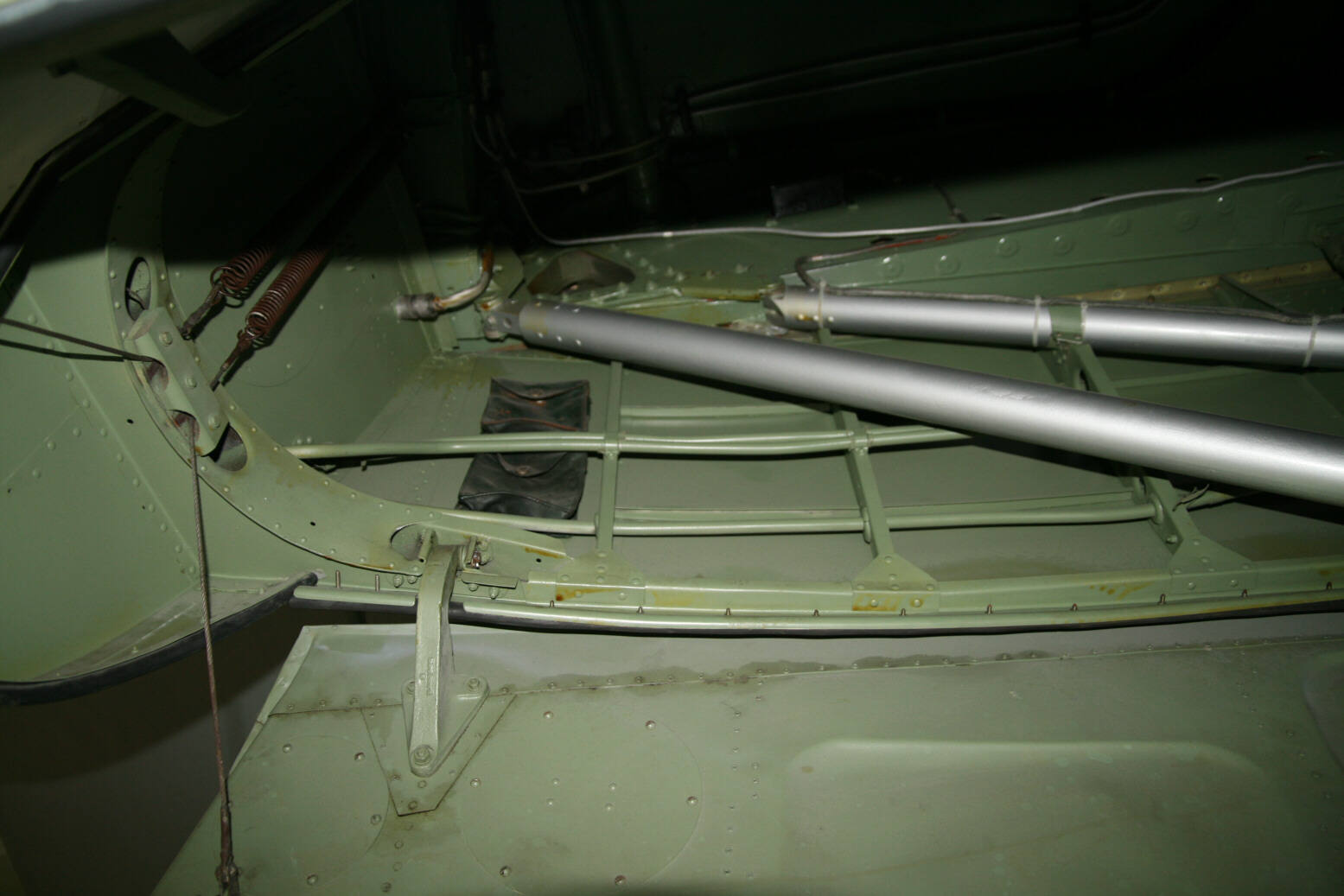
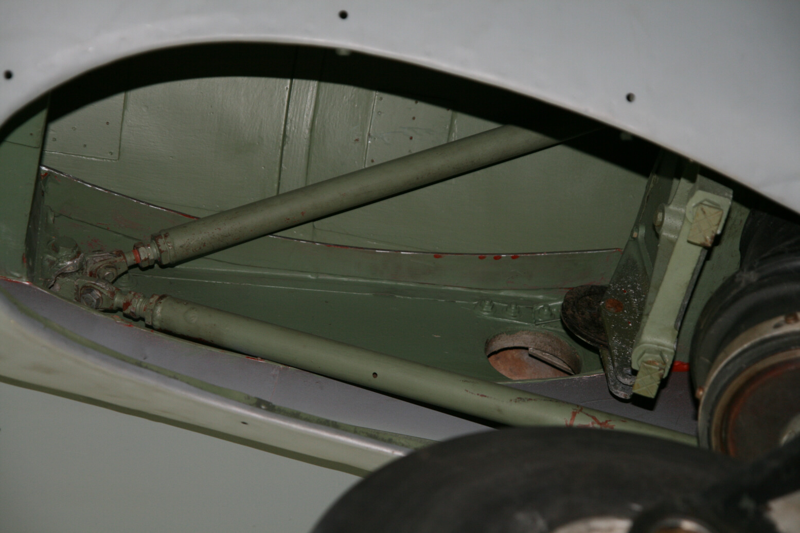
Pictures 17 and 18 (below) show the end part of both bays (pictures viewing upward), picture 17 the port bay and 18 the starboard bay. I have shown them together this way so you can appreciate the small differences. The back bulkhead in both pictures is to the left. In front of the back bulkhead are two door-cable springs (in picture 17 one spring looks like the shadow of the other one but it is a separate spring). To the right of this is an angled ‘block’ that is the rear spar. The angle is clearly reversed as expected.
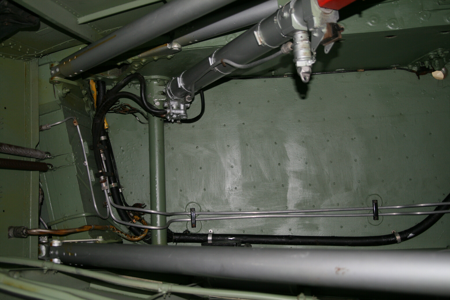
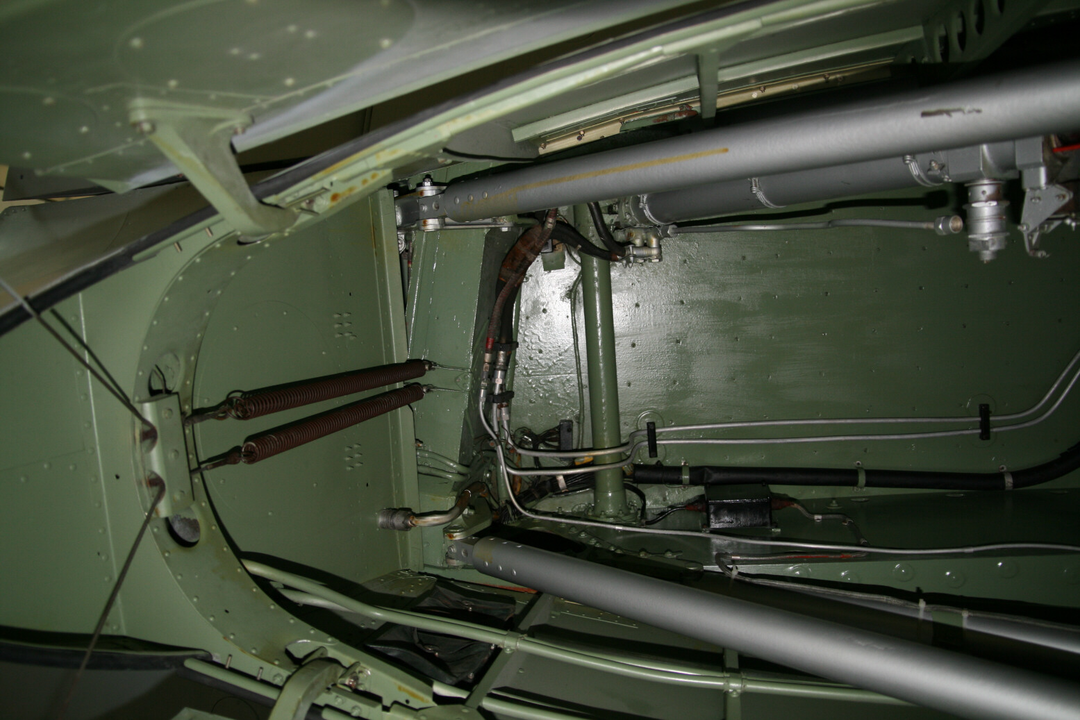
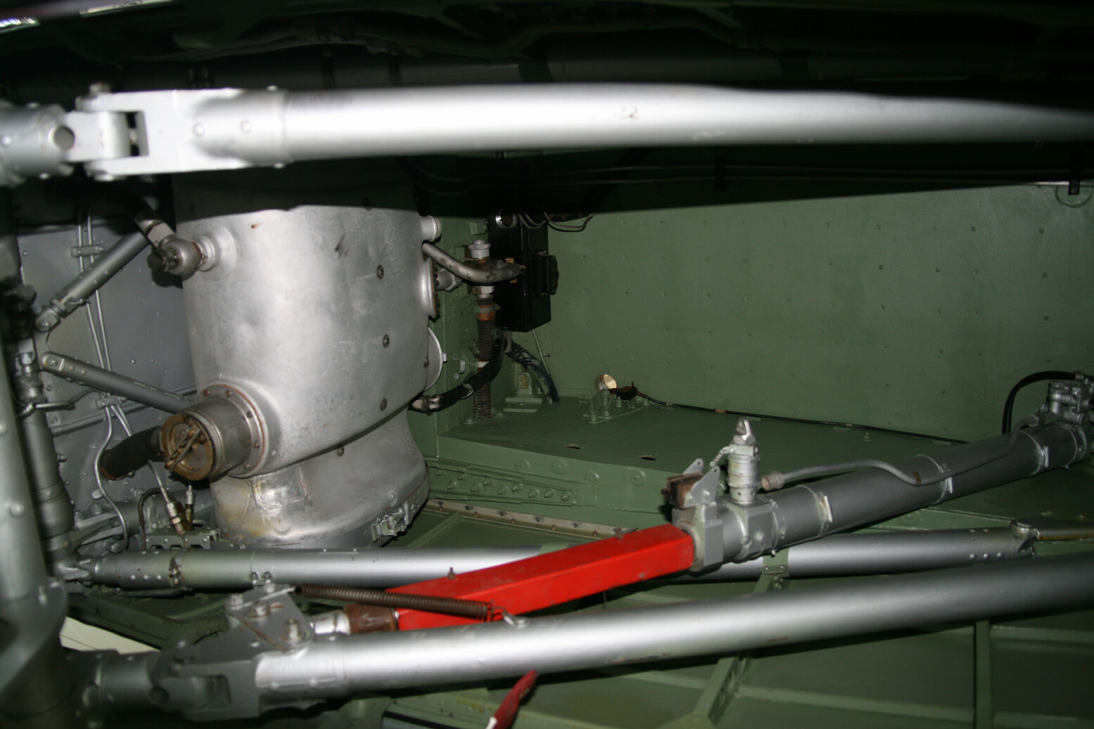
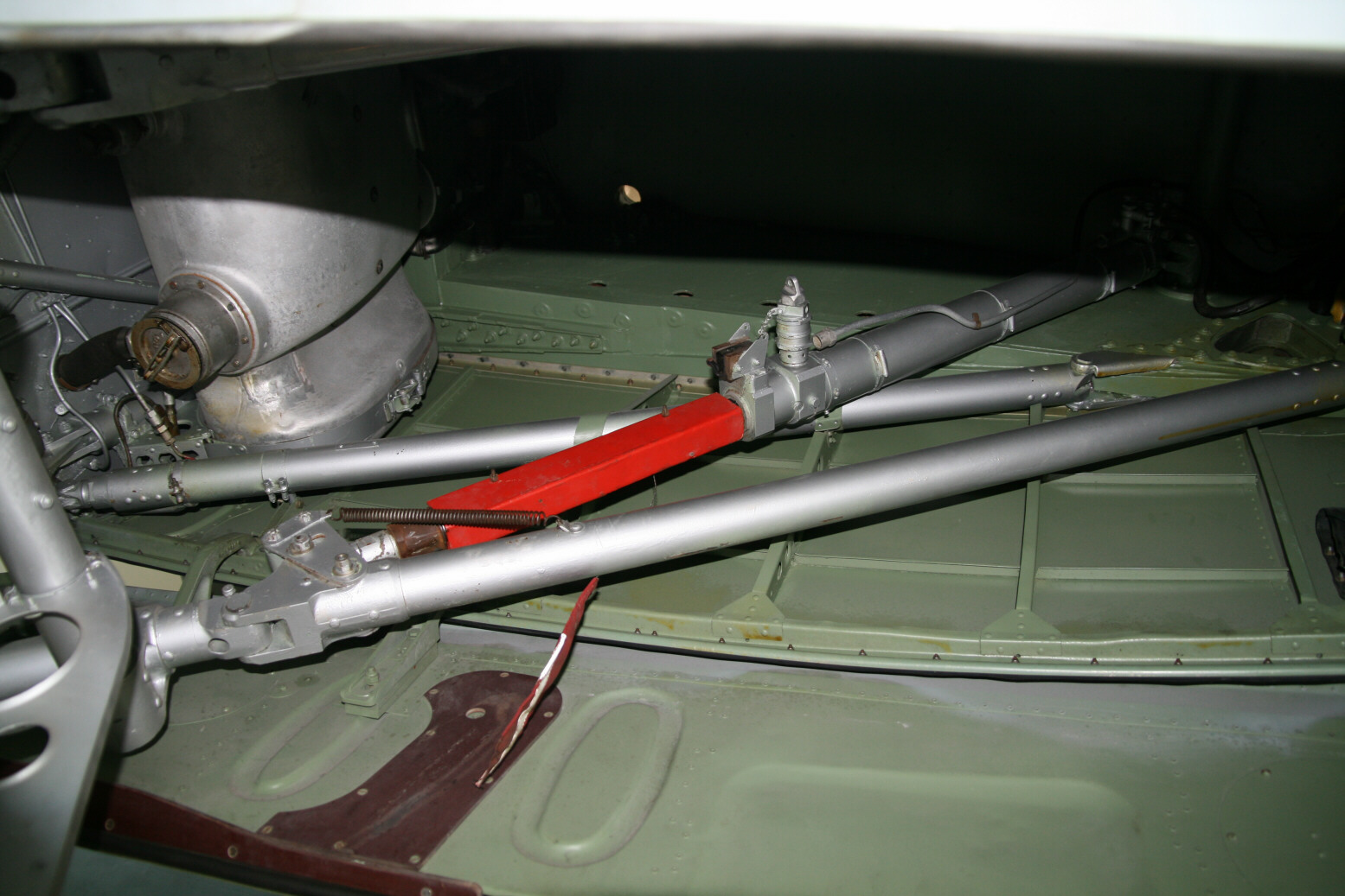
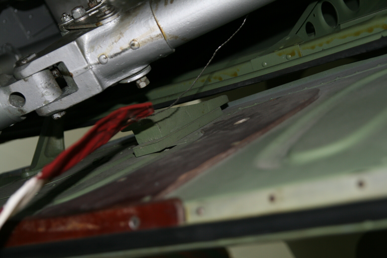
Connected to the rear spar are the two silver-painted rear struts of the undercarriage. Attached to one of those (out of sight to the right) is the other silver-painted tube which is the hydraulic jack for lowering/raising the undercarriage. There is a red U-shaped sleeve around it but that will not be standard (it blocks the undercarriage movement). The jack is connected to the green-painted bar running across the bay. There is a further pair of rear struts (for the fixed part of the undercarriage) but these are hidden behind the lower rear struts (they are visible in other pictures, for example 20).
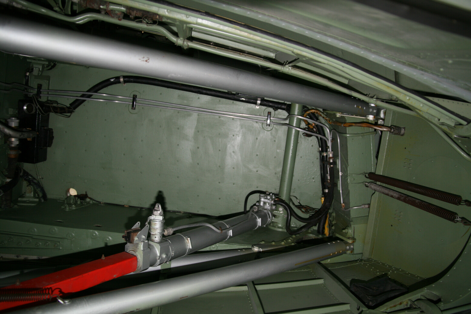
There are wires and pipes running in the bay. The thick black pipe running along the port side (bottom on the pictures) is electrical. Just behind the green bar it splits into many separate electrical wires. In the starboard bay the wires are then collected again into another tube that runs along the back to exit on the starboard side. In the port bay the wires run directly aft and exit there (so the port side). There is an electrical junction box mounted near the top port side of the bay. The electrical wire (orange-brown) going towards the back plugs in through the back bulkhead, once again in the same place in both bays.
The pair of aluminium tubes running from front to back are hydraulic lines for the undercarriage jack. There is a difference here as the pair in the port bay go straight up front while in the starboard bay they angle off to starboard near the front.
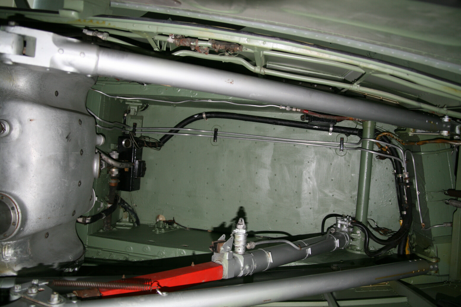


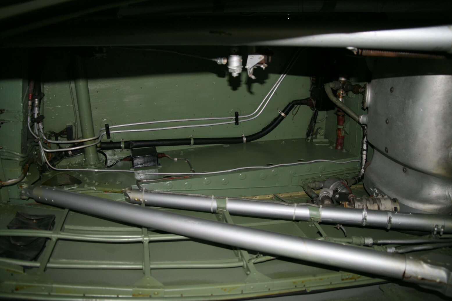
There is a pair of green-painted pipes, function unknown, running along the port side of the bays. Pictures 19 through 25 (above) are further pictures of the port bay, under various angles. Note that picture 18 is rotated relative to the orientation it was taken for easy comparison with picture 17. I tried to rotate the other pictures of the port bay as well but it just looks weird so they are in their original orientation (mostly flipped relative to 18).
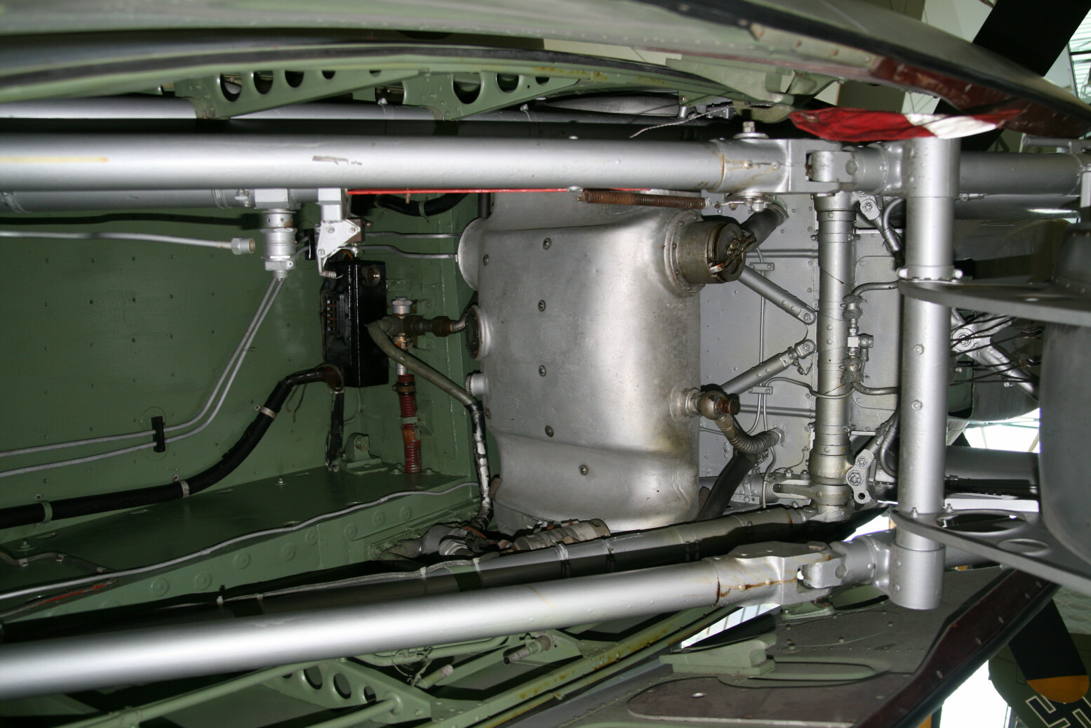
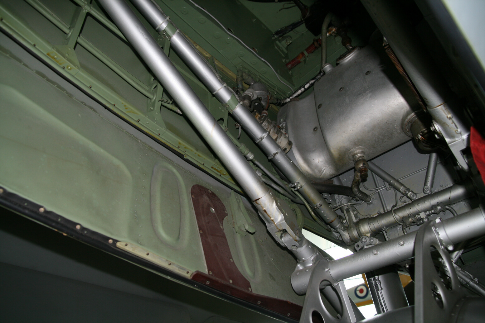
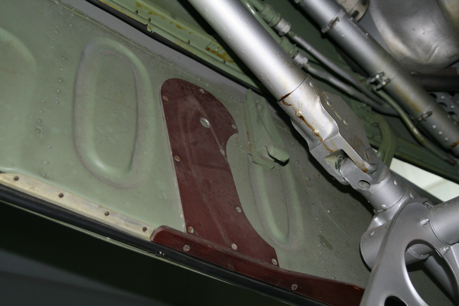
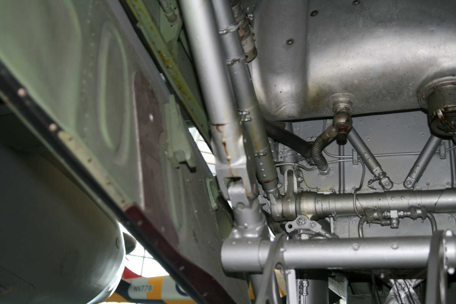
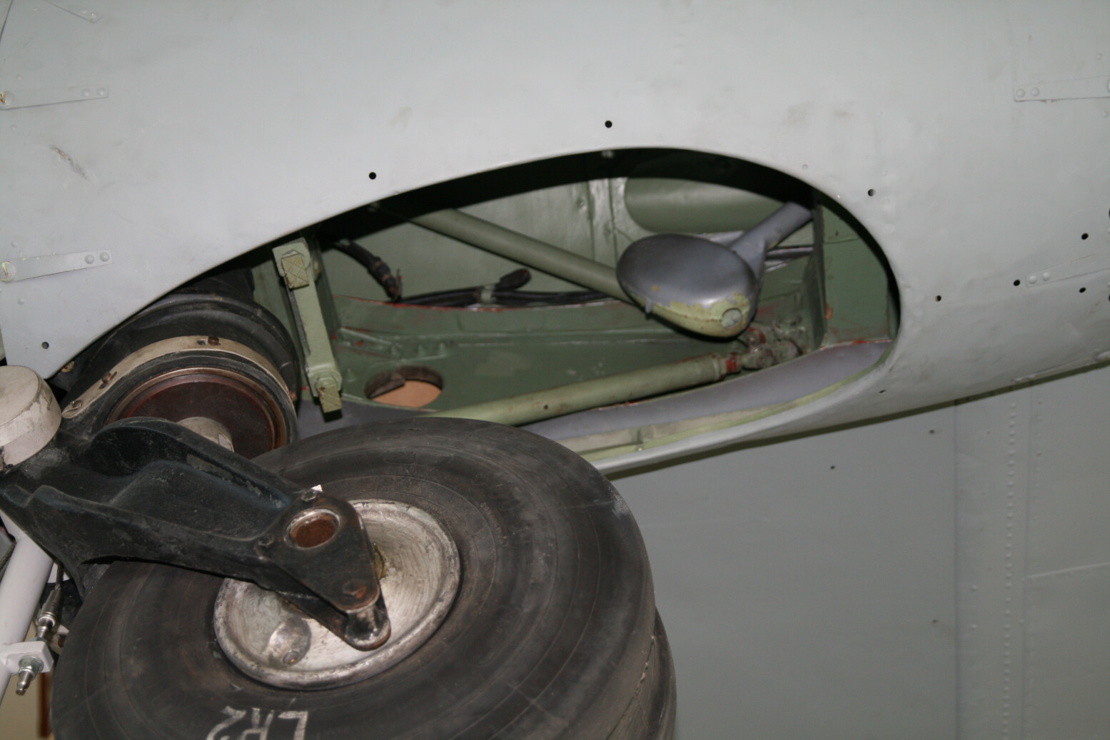
Picture shows the front part. You can see the hole in the roof along the side of the bay, almost in the centre of the picture. The big silver tank is the engine oil tank which is mounted behind the main undercarriage legs and V-shaped strut. The bulkhead between the engine and the bay is painted silver here. There is a black junction box at the top front. This box is different for the two bays. Just below it is a ribbed pipe which is the fuel line to engine. Also this is asymmetric in the bays, always coming from the inboard side.
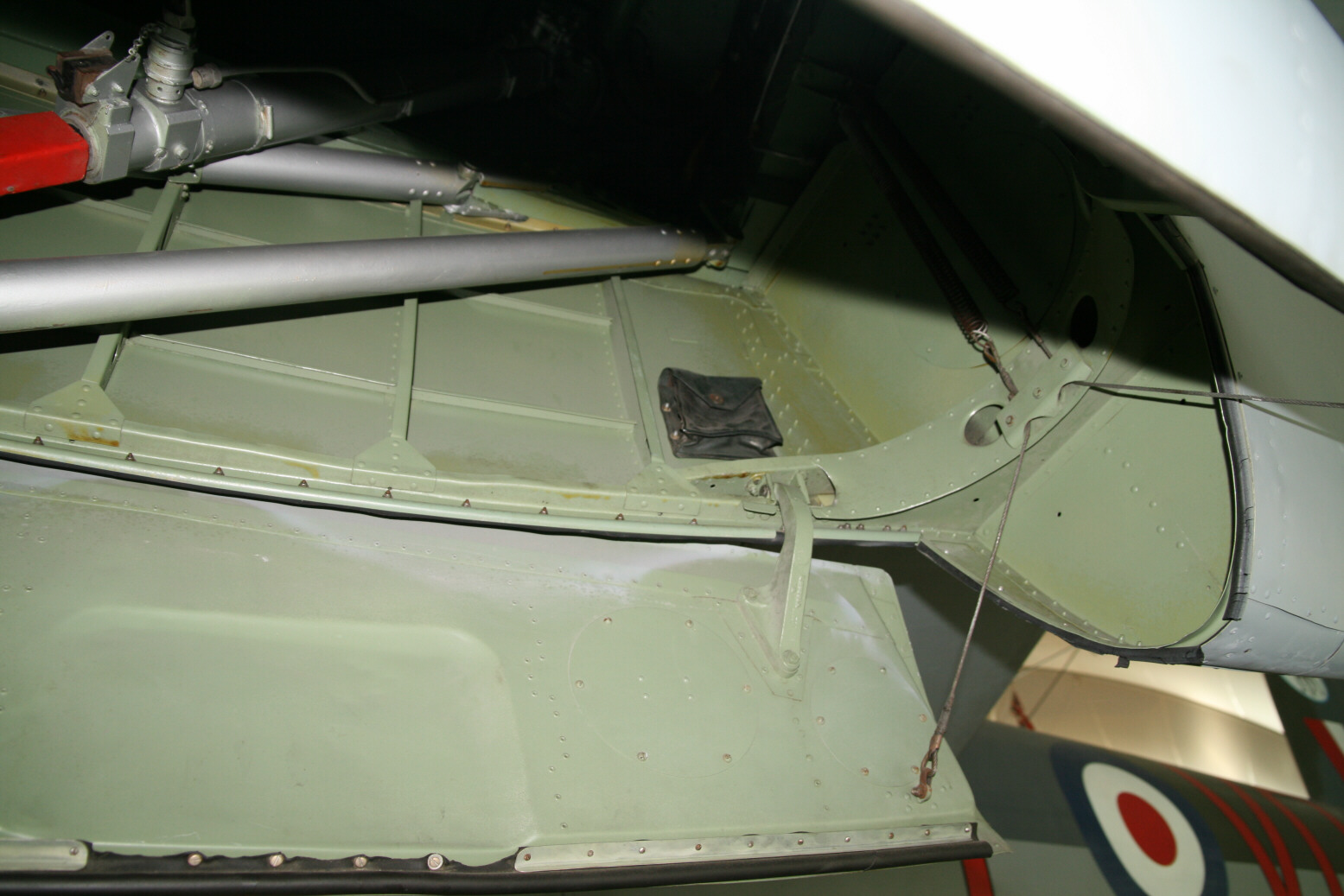
Picture 21 shows that there is a third green pipe running along the port sidewall but its location is recessed so it doesn’t show up if you sight along the side. Picture 23 shows a small bag hung on the sidewall. In the various pictures you can see that the sidewall ribbing doesn’t stretch all the way out front and back and is absent next to the oil tank and the last panel (the one with the small bag).
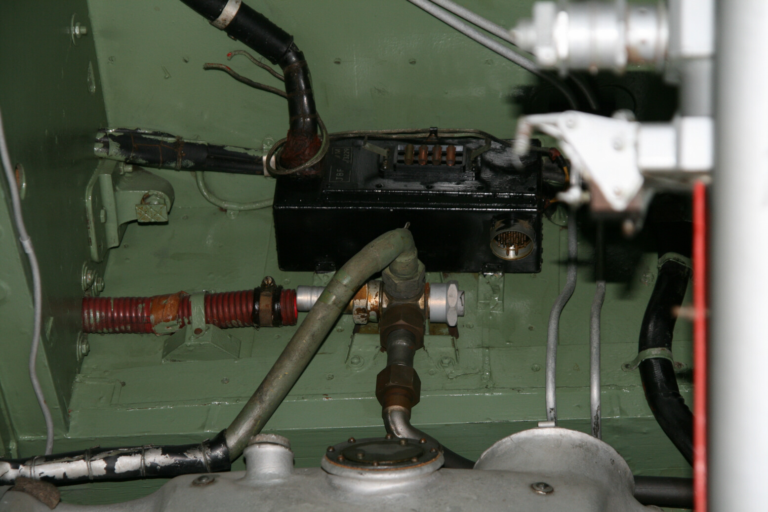
Picture 25 shows the junction box and fuel pipe in detail. Note that the silver pipe running at an angle down towards the oil tank is connected to the fuel line, not the junction box. It angles further behind the oil tank and goes to the left (its top is just visible above the oil tank). The pair of aluminium pipes running to the port side of the junction box are the hydraulic lines.


Pictures 26 through 35 (above) show a similar series of shots of the starboard bay. Picture 26 shows again the junction box and the fuel line. The hydraulic lines pass on the other (starboard side) of the box. The box itself is mostly symmetrical, the only part that is reversed is the connector at the bottom. As stated before, the fuel line comes in from the other side but the silver pipe going on goes to the same side (port in both bays). Picture 35 shows a filter mounted on the port sidewall. I have not noticed this filter in the port bay but in view of its location it would have been difficult to see so it quite well may be there.
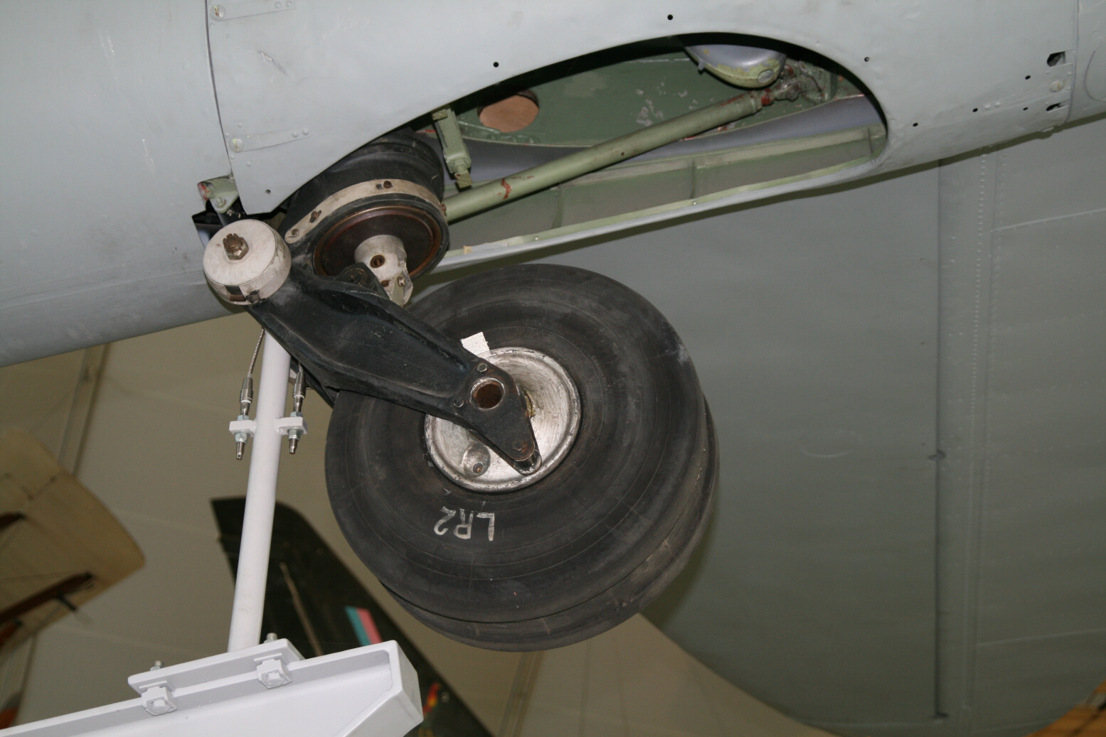
On to the main gear construction. Picture 36 shows the tyre with its typical tread pattern. Pictures 37 and 38 shows the port wheel from either side (37 is inner, 38 is outer). Clearly seen are the symmetric brake lines. The rubber of the tyres is badly cracked by now (obviously not a standard feature). The large bolts near the brake lines are also not original features but belong with the stand the Mosquito is on.


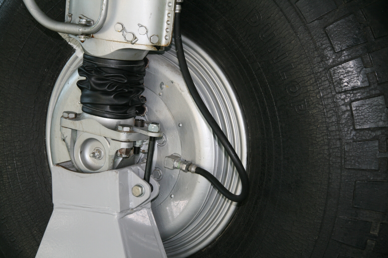
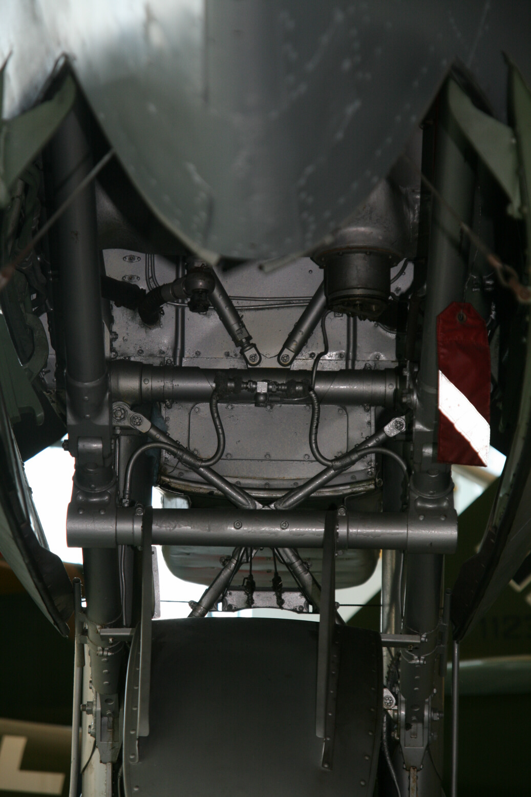

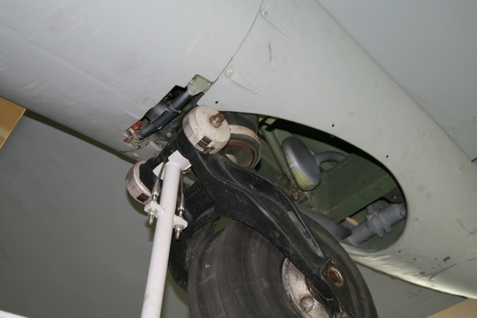
The main undercarriage consists of two main front legs (the shock absorbers are rubber blocks inside the legs) that pivot back along hinges on a cross-bar just above the bottom of the bay at front (well visible at the bottom of picture 34). Above this is the fixed part. Two nearly vertical legs go up along the front bulkhead (they angle out slightly towards the top). The bracing is done by (upper) struts going towards the back of the bay. Between the vertical bars is a V-shaped strut. The strut towards the back is again well visible in picture 34), while the vertical leg is nearly hidden behind the oil tank. The bottom of the V-shaped strut is also visible. The main legs are retracted backwards by the lower rear struts that are connected to the hydraulic jack. These struts are connected to pivots on a cross-bar from which the mudguard is hanging (picture 30). Between the main legs are cross-braces, consisting of an X with its bottom duplicated on front and back (inverted V’s) Picture 39 shows the cross-brace but at such an angle that you cannot see that the bottom consists of the two inverted V’s. Picture 39 was actually taken because it shows the brake lines very well. To the right of the bottom bracing V (the upper, fixed one, behind the oil tank) there is a thin aluminium pipe coming down, connecting up to a construction at the back of the pivot bar. From there lines go either side (a ‘hat’-like shape) and then run down the inner back side of the main legs to the wheels (picture 40).
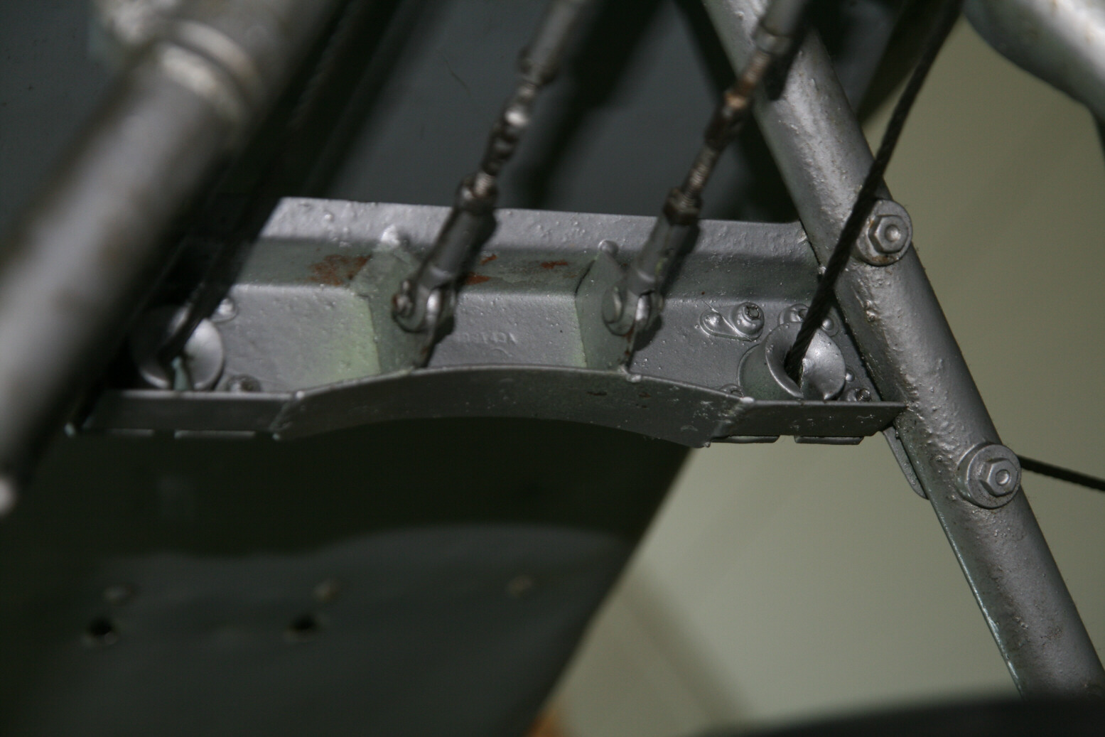
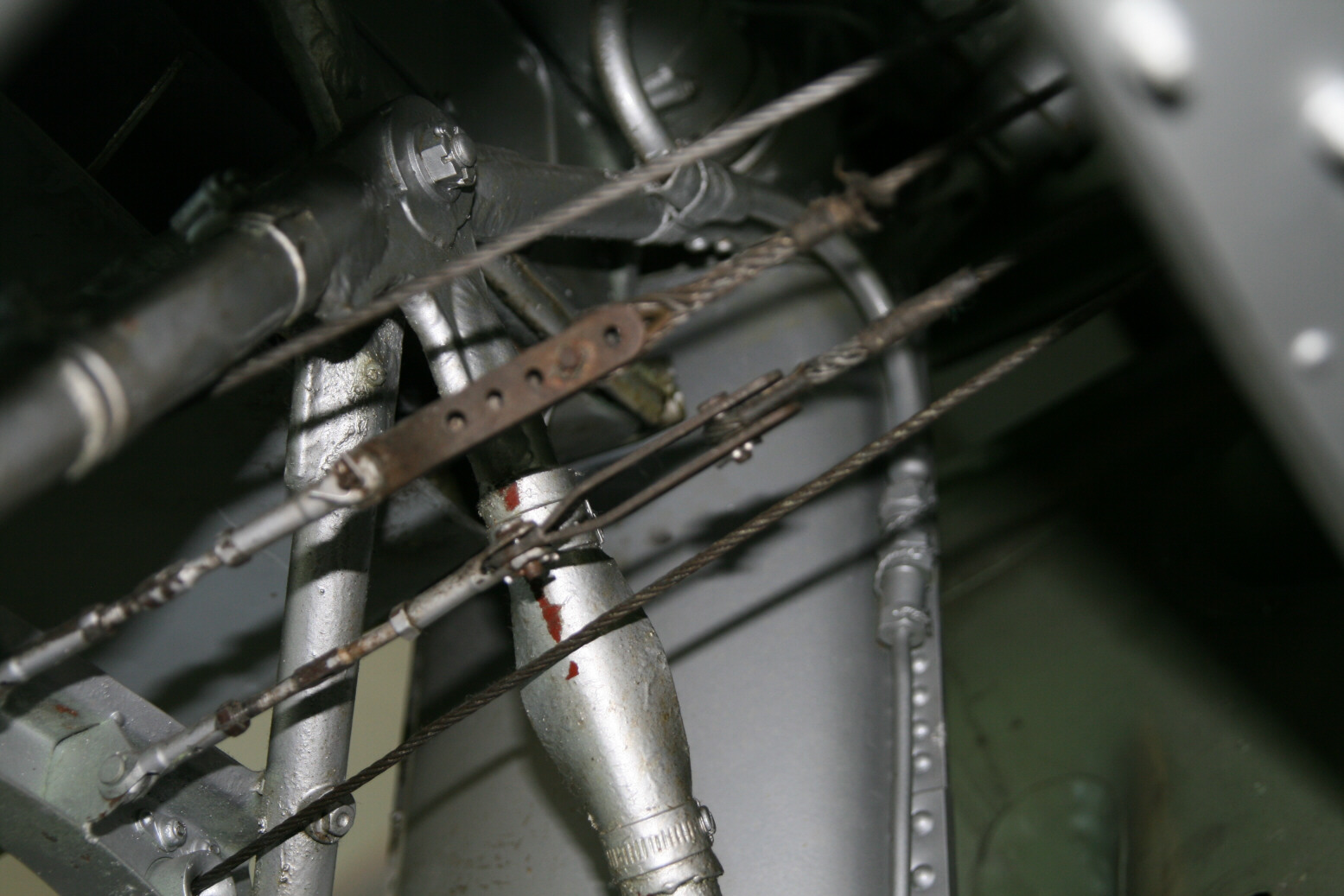
The doors do not have separate controls. They are simply pushed open by the undercarriage gear (fenders are mounted on the main gear legs for that) and closed by a couple of cables attached to front and back of the door. The front cables are attached to the brace between the main legs. They start at front, run towards the back, past a couple of wheels where the port cable crosses over to starboard and vice versa, then run to the front again through holes in the front bar, then sideways over rollers (picture 14) that protect the main legs and then on to the corner of the door. Pictures 41 through 43 show the front-cable construction. Unfortunately picture 41 is out of focus but you do get the idea. The front brace through which the cables pass (and start at the back of it) is mounted on the front bottom of the X, while the back brace is on the back of the back bottom of the X. The front V is protected against the cables by pieces of rubber fixed with hose clamps.
The back cables are attached to two springs that run vertically against the rear bulkhead of the bay (for example, picture 33).
Pictures 44 through 49 show details of the doors. Picture 44 shows a bulge on the outside. This corresponds to a green-painted ‘hook’ on the inside (pictures 45 through 47). There are also brown (probably bakelite) panels for reinforcement or protection. Pictures 48 and 49 show the door hinge.

Tail Wheel
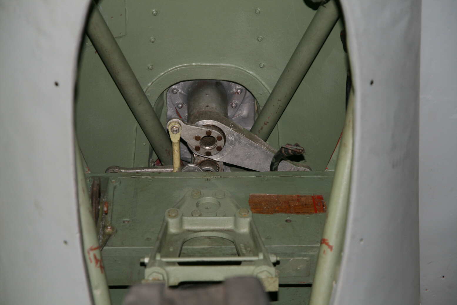
Pictures 50 through 56 show the tail wheel and its bay (during flight the wheel is partially retracted). Picture 54 shows the view looking forward over the tail wheel. I’m guessing we’re seeing the rudder actuator.


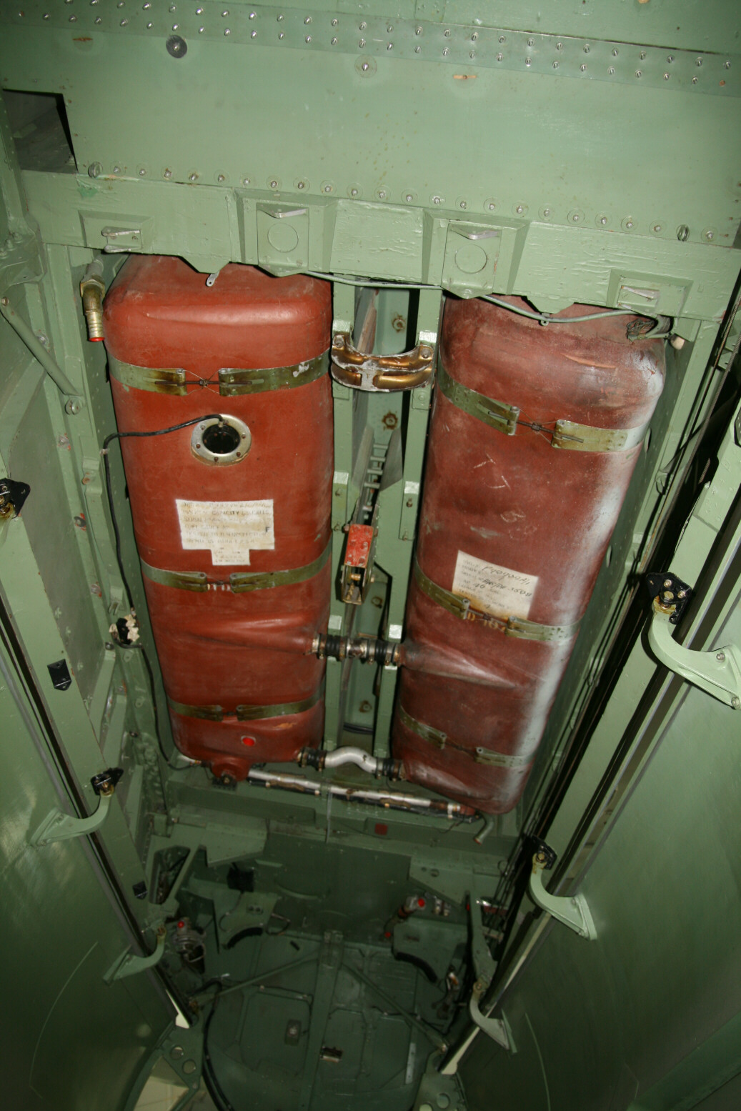
Bomb Bay
This Mosquito has an enlarged bomb bay with extensions of the fuselage at back and front of the bay. Pictures 57 through 61 shows various items. Towards the back on the starboard sidewall is the fuel distribution unit but it is too far away to be seen. The fuselage fuel tanks are well visible. The front of the bomb bay, bulkhead 2, normally sports an enormous number of pipes (hydraulic and pneumatic) but in this particular Mosquito it all has been removed (looks like cut off with pliers) so there is no point in a picture.

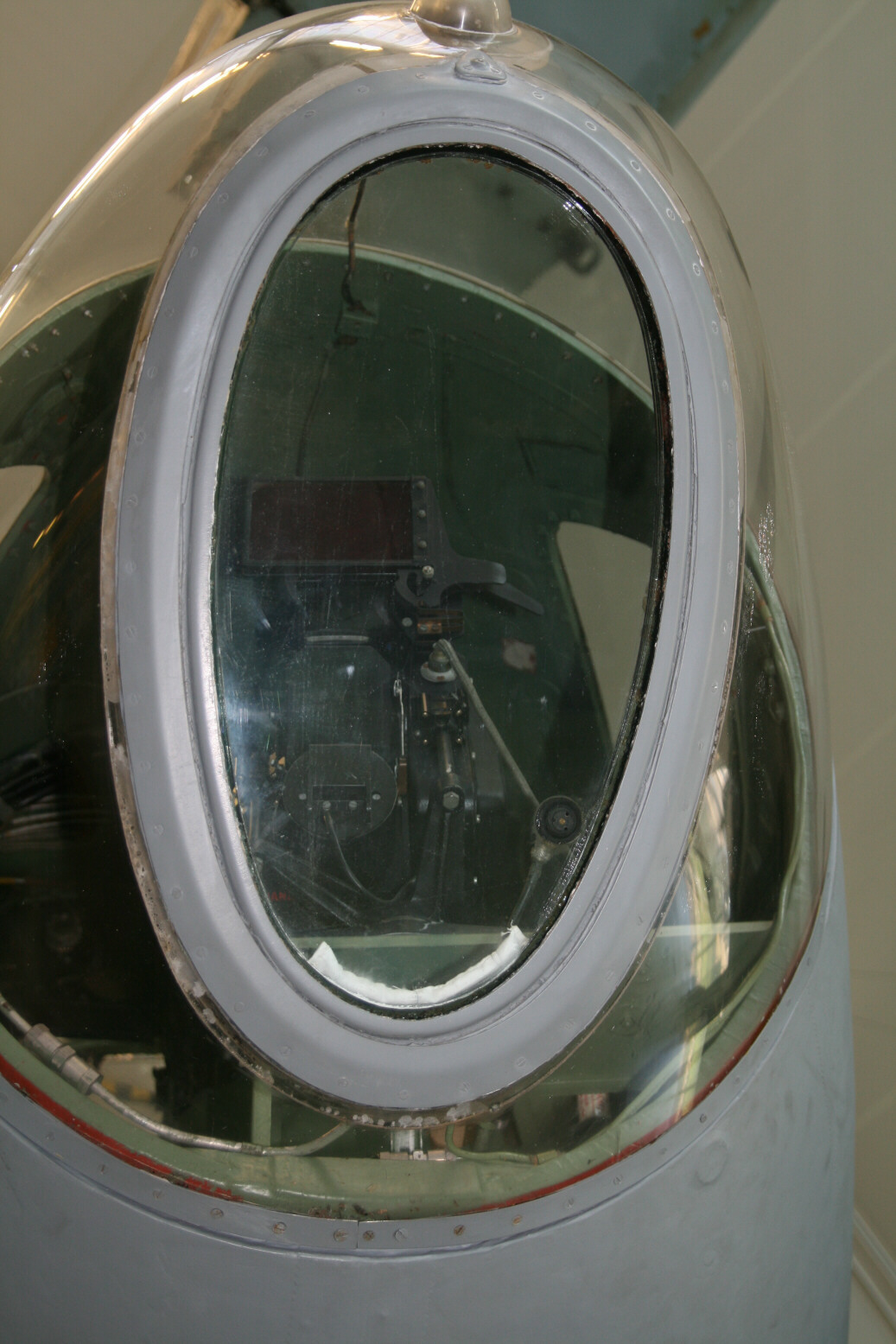
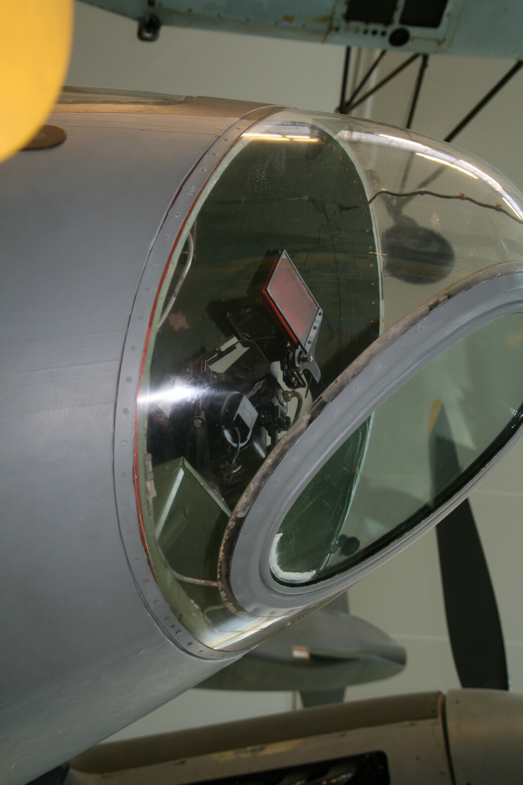
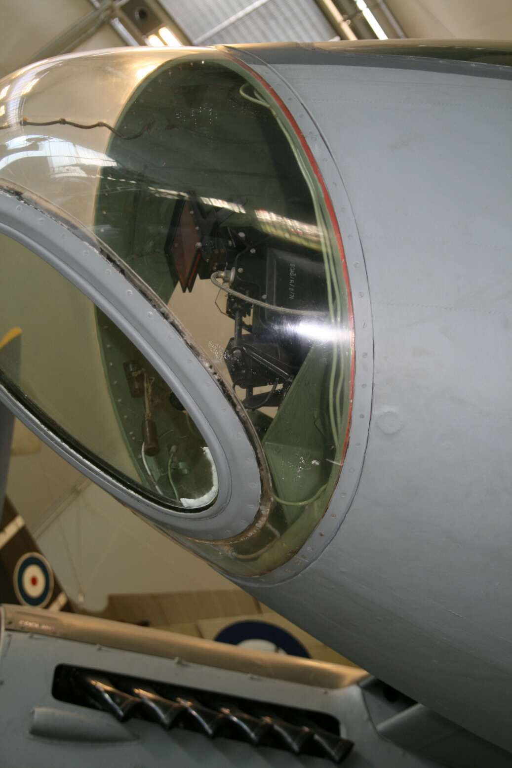
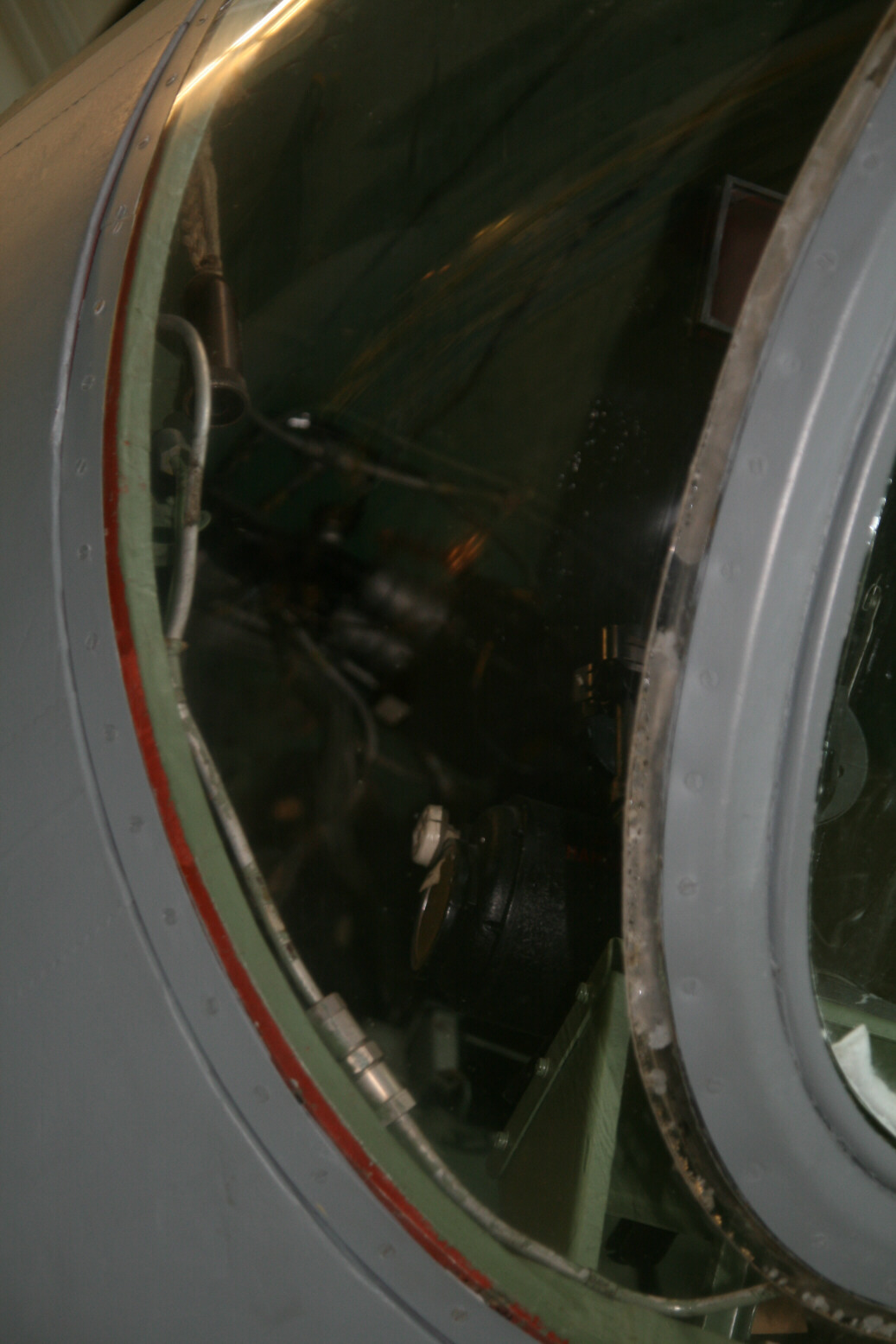
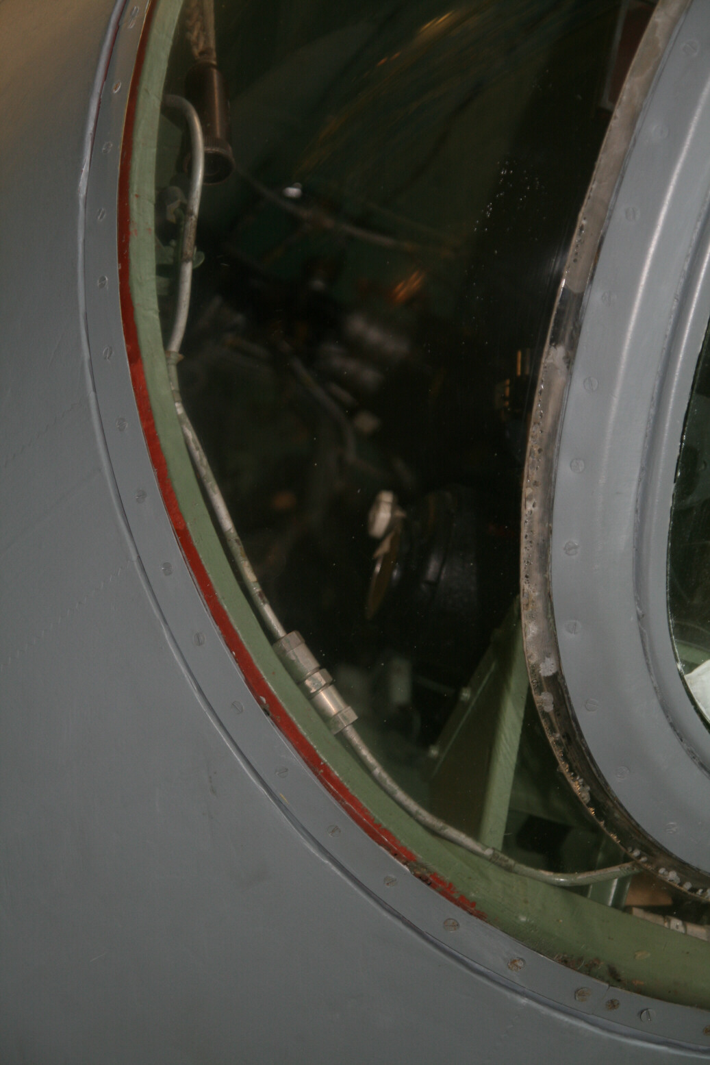
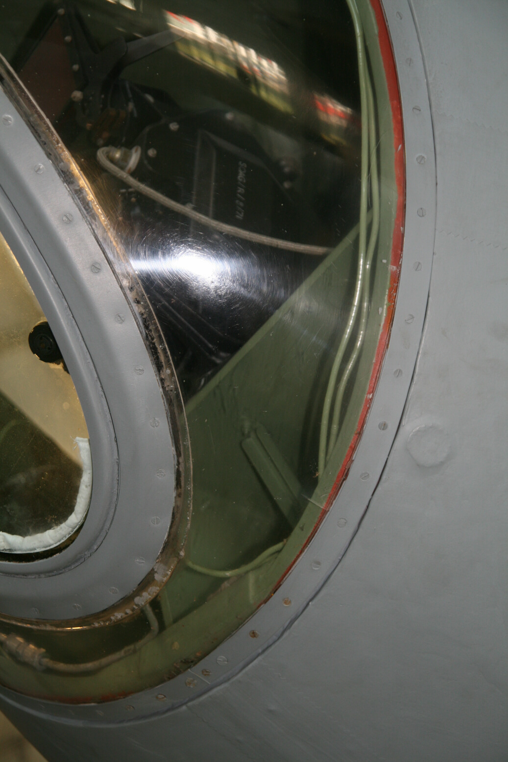
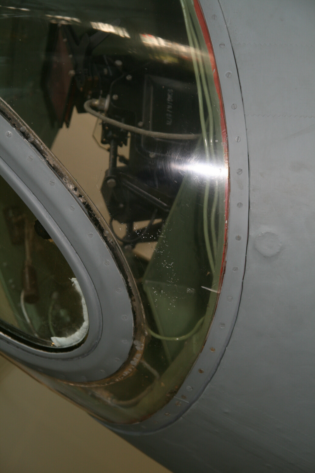
Cockpit
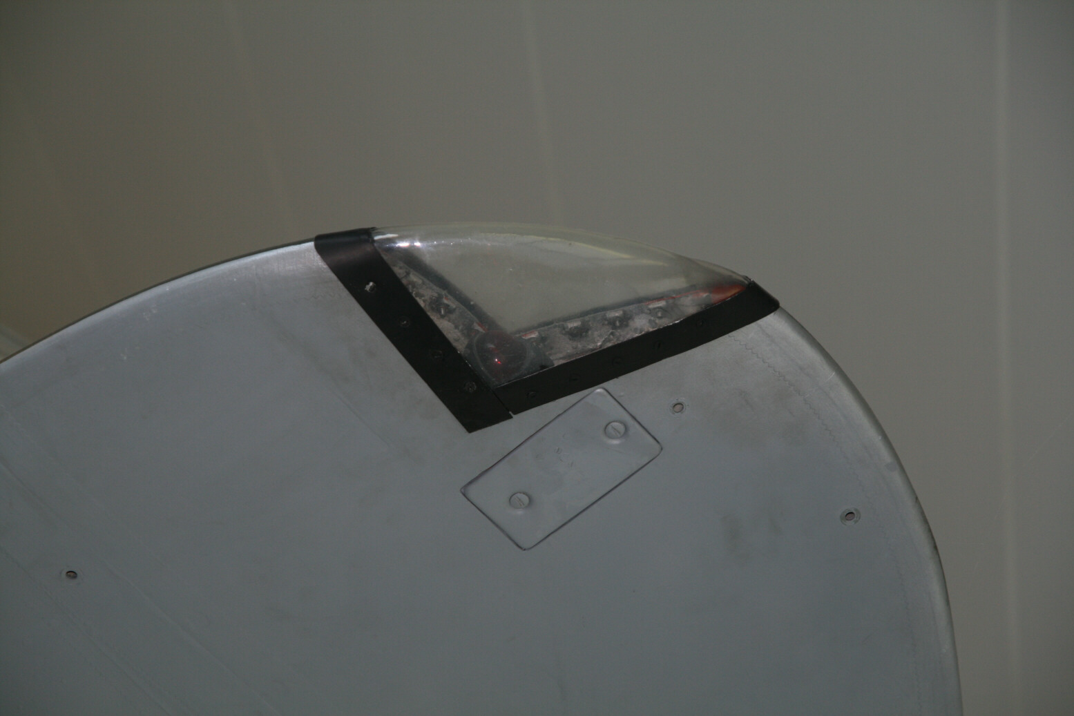
Picture 62 shows a front view of the bulges on the canopy. Pictures 63 through 69 shows the nose with the bomb aimer’s position. There isn’t much visible further inside, the angle is wrong for seeing the back of the instrument panel and you cannot step further back.
Various
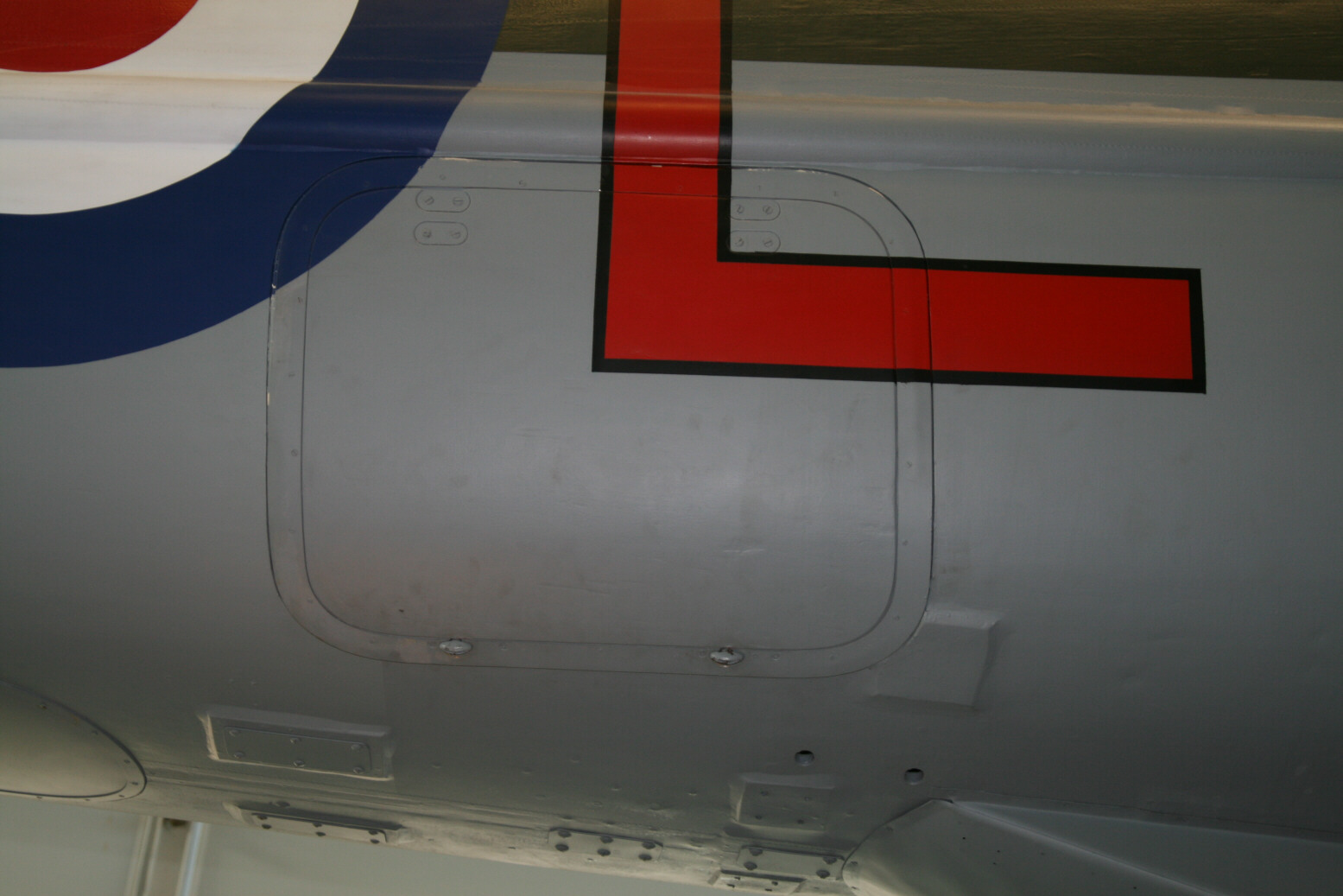
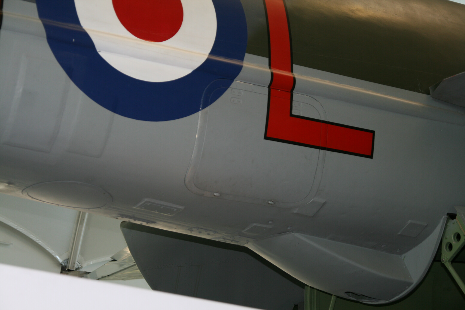
Pictures 70 through 73 show the side entry hatch underneath the reinforcement strake. This Mosquito also has a number of reinforcement panels sticking out on the starboard side and the bottom (pictures 70 through 75). Pictures 74 and 75 also show the identification lights (white, amber, green).
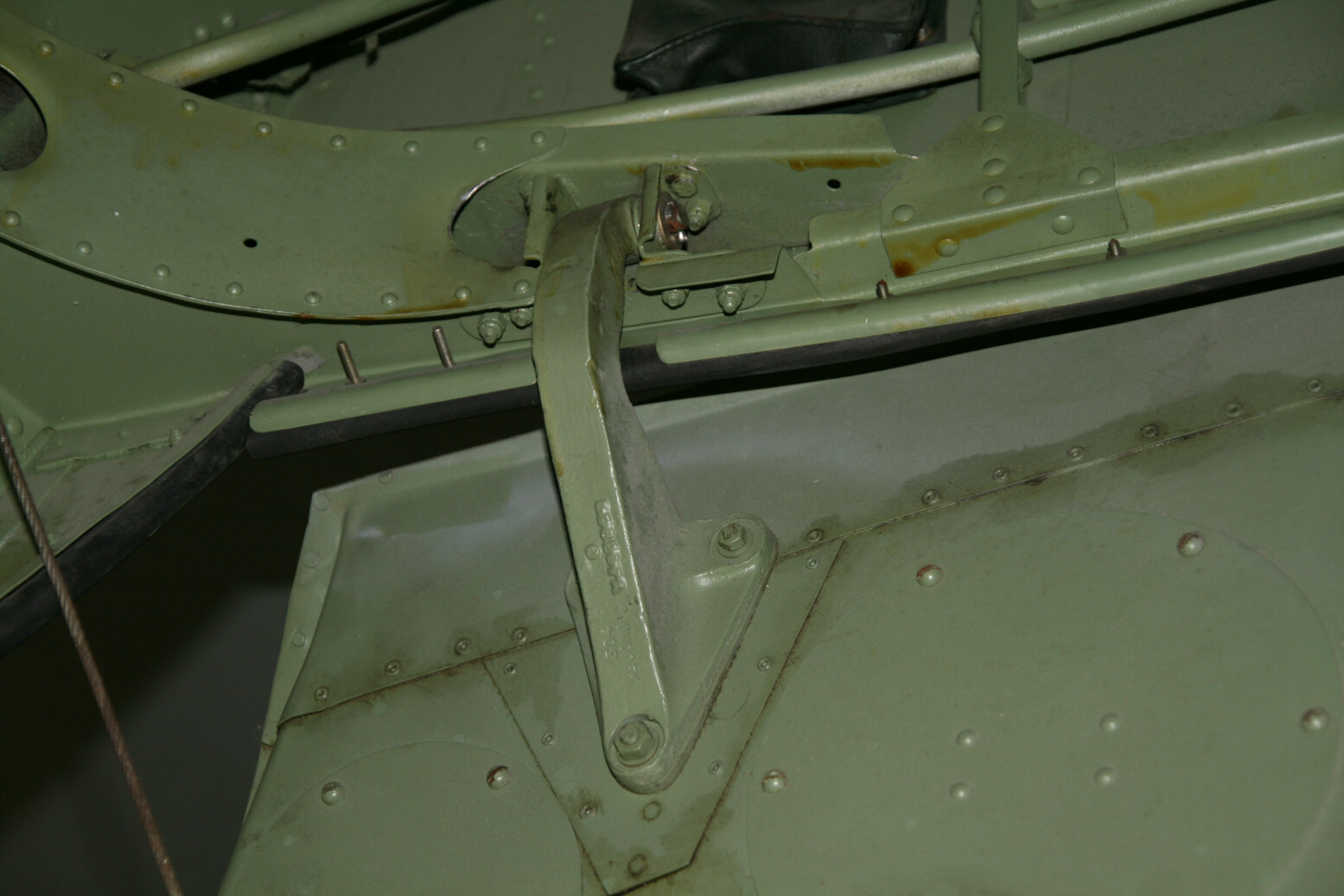
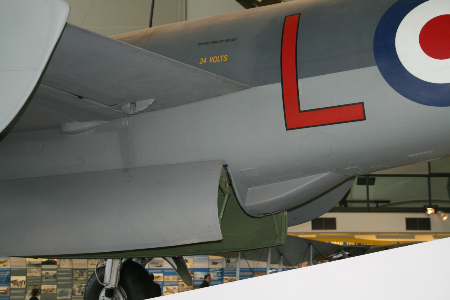
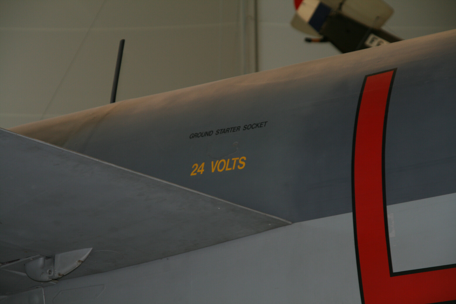
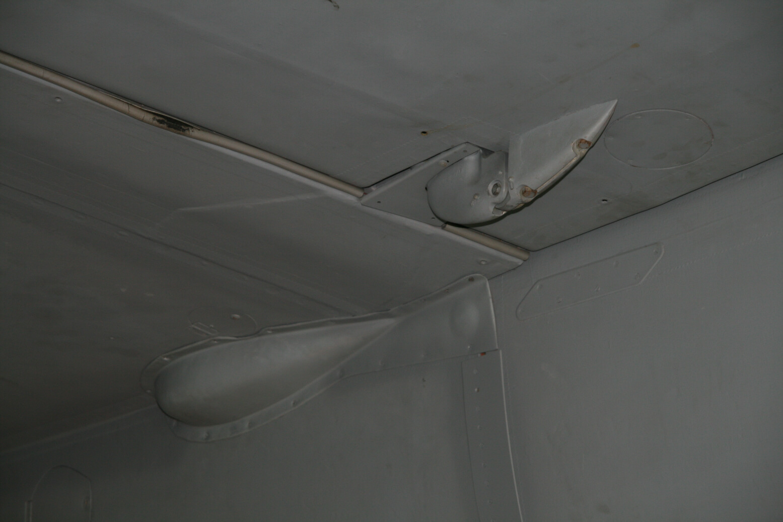
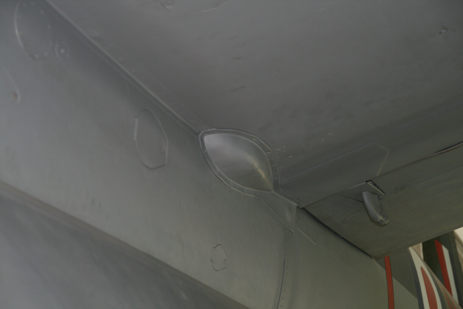
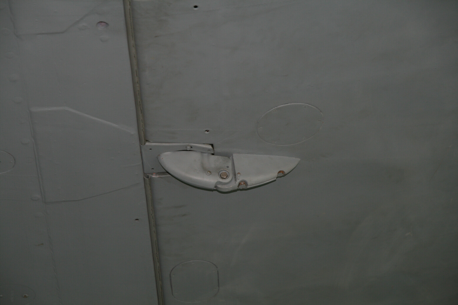
Picture 76 shows the location of the ground connection socket (port side of fuselage, aft of the wing). It also show the inboard flap hinge. The flaps hinge on an axis that is eccentric to the flap itself (the bolt through the two parts of the hinge). Other shots of the inner flap hinge are in picture 78 and 79, which also display the bulge at the connection between the wing and fuselage.
Finally, picture 79 shows the outer port flap hinge.


© Max Otten 2013
This article created on Tuesday, November 26 2013; Last modified on Wednesday, March 30 2016