
Pacific Coast Models | 1/32 Fw 190A-1/2/3
Reviewed by Ray Peterson
The latest kit from PCM is the early versions of the well-known Focke Wulf Anton. These early models are the fighters that sent chills down pilots and staff of the RAF, and pressured the British into developing the "stop-gap" Spitfire IX. Being a Luftwaffe aircraft, I know this one will be in the cross-hairs of all the so-called experten, so I pulled out every reference I could find on this aircraft. This list includes the Aero Detail #6 "Focke-Wulf Fw190A/F"; AJaKS "Model Fan Encyclopedia No. 3: Focke Wulf Fw 190"; Model Art "Focke-Wulf Fw190A/F/G"; CMK Photo Hobby Manual #1501 Special Drawings: Focke Wulf Fw 190 part 1"; Osprey Publishing "Production Line to Frontline #5: Focke-Wulf Fw 190"; as well as the article on the excellent IPMS Stockholm site entitled "Modeller's Guide to Focke-Wulf Fw 190 Variants; Radial Engine Versions Part I", located at http://www.ipmsstockholm.org/magazine/2004/11/stuff_eng_fw190_01.htm. I highly suggest reading this article as it provides a nice overall guide to the different early model Antons that can be a big help in understanding the kit's options.
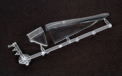
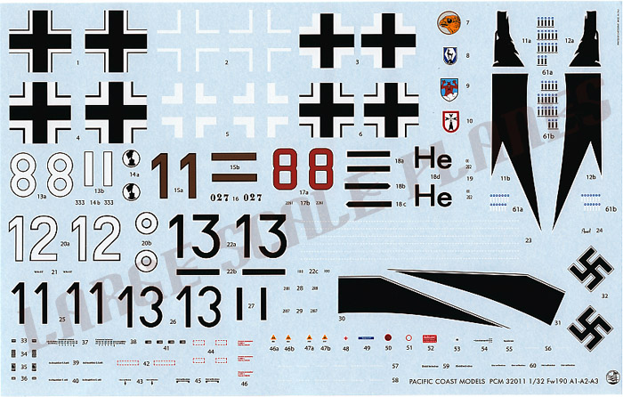
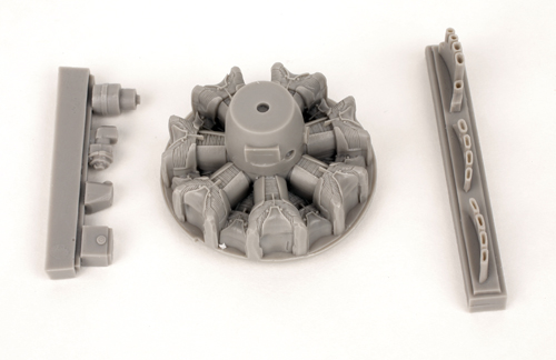
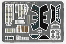
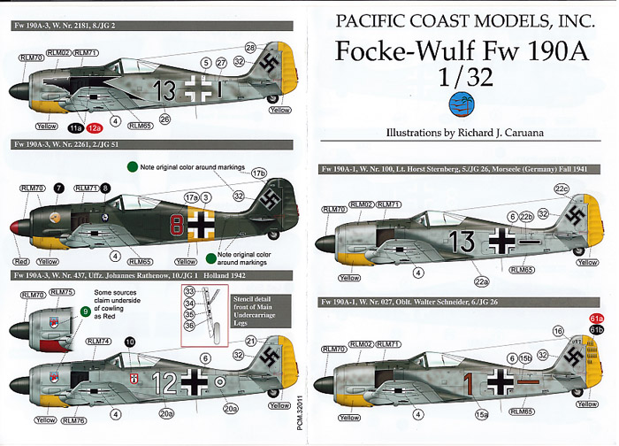
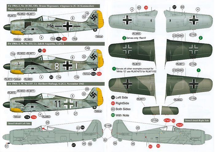
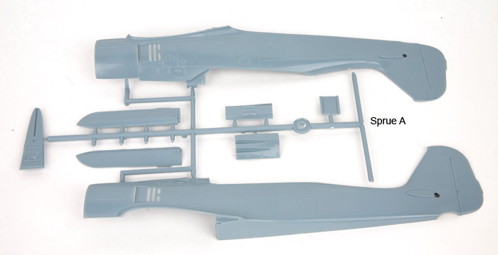
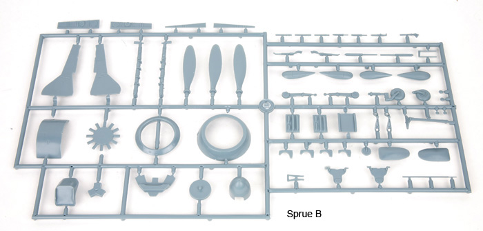
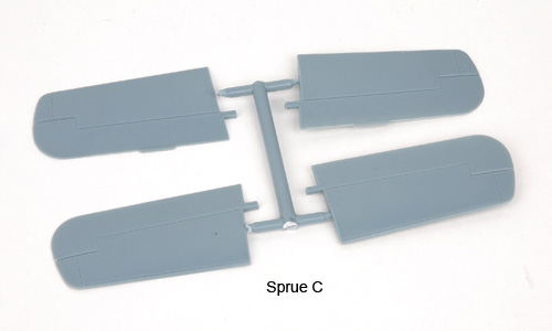
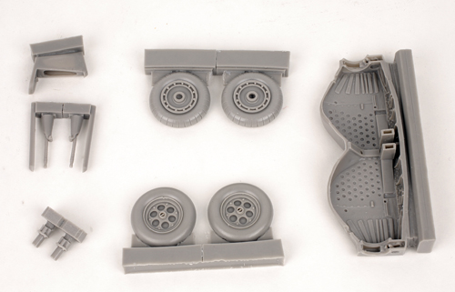
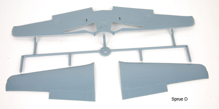
The kit is presented in PCM´s now familiar glossy grey plastic. There are 76 grey plastic parts, 5 clear plastic parts, 20 resin parts, and 45 PE parts. Decals are provided for 5 aircraft, including for 2 A-1s, 1 A-2, and 2 A-3s, as well as typical stencil decals for one aircraft. Instructions are exploded view line drawings on nice glossy paper and seem to be clear, with color suggestions given by name, no manufacturers paints are listed.
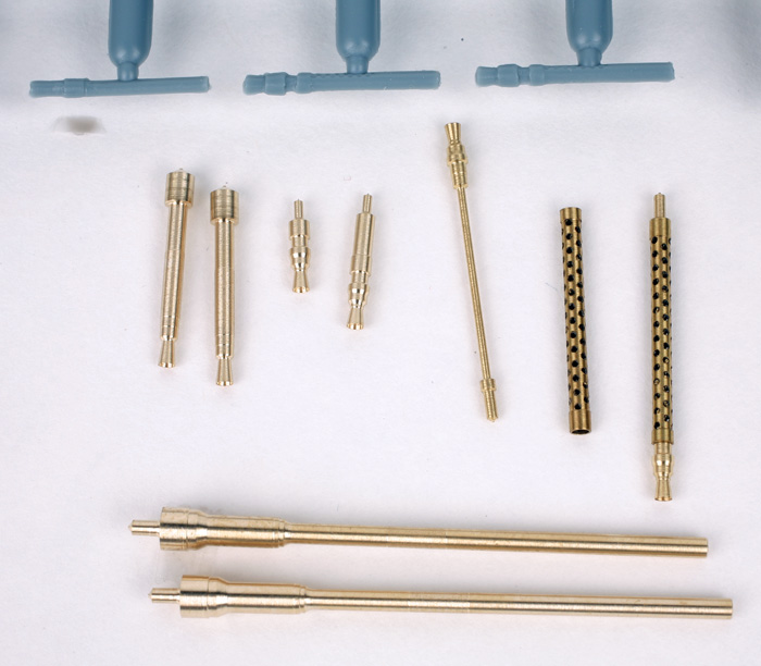
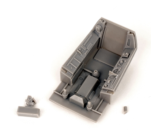
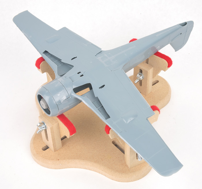
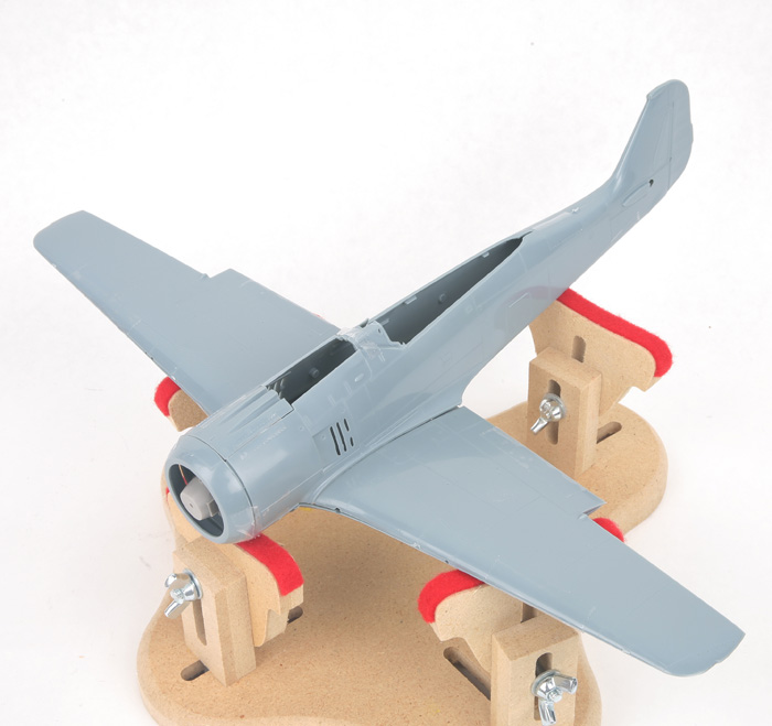
Scaling up some drawings, the kit matches well. Panel lines and access panel outlines are finely engraved. Larger fasteners are represented, but not typical lines of rivets. Comparing to several references, detail is very complete and accurate, although detail is a little soft on some of the small parts which is pretty typical for short-run kits. I have dry-fitted the major parts to check on fit (see photos). For a short run kit the fit is pretty good although there will be a little work required with the multi-piece cowl/ fuselage/wing connections. There will be some work too on the joint each side of the fuselage gun cover, part A6 as there shouldn´t be any joint line, it is one piece. Likewise for the rear of part B35, the lower cowl, as there shouldn´t be a joint there, either. Also, to properly fit the under-fuselage resin exhaust part, you will need to open up the separate opening for the short exhaust. This opening is molded as filled in on part D62, the lower wing piece. A curious omission is the MGFF cannon barrels for the outer cannon ports. These barrels are needed for all versions. However, as all the barrels fall into the soft-detail category, I suggest replacing them anyway so this is not a huge problem. Master Model of Poland offers all three barrels, MG-17, MGFF, and MG151 barrels, which are incredibly detailed. (See comparison photo, which also shows an extra barrel that might have been for the MGFF, but only one is there.) At this time, the only way to get the MGFF barrels is by buying the barrel set for the Bf 109E-3 through 9 set, in which you also get two MG17 ends of different lengths for the offset guns of the 109, but I think you could make the set work for this kit, too, by simply gluing the barrel ends to some scrap plastic tubing to use them for the fuselage MG barrels. By adding either the separate MG-17 set for the wings for the A-0/A-1 or the MG151 barrels for the A-2/A-3 kits, you have it made. Probably we will see a couple of specific sets offered soon for the PCM kits; either packaged by Master Model, or Montex in their KAM series which packages the Master Model barrels with vinyl mask markings options. Another small point is in the cockpit, which is quite well done with a mixture of plastic, resin and PE. It appears from my references to be very accurate, with the exception that one of the few photos of an A-3 cockpit shows the bank indicator should be one instrument over from where the pre-painted PE has it located, and it appears the instrument given is of a later style than the one in the pictures.
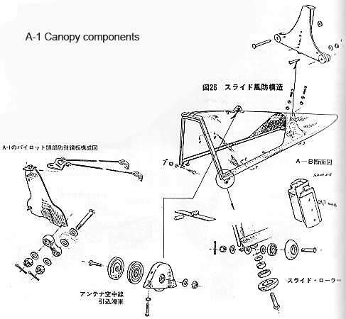
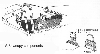
Looking at the possible versions that can be built with the kit, let´s start with the A-0. Although the kit does not advertise itself as an A-0 on the box top, it does have the cheek blisters as separate parts, and provides the symmetrical teardrop-shaped cowling cheek blisters of the A-0, which is a nice touch. The kit also includes an insert to plug the cooling gills behind the cowl, although filling and sanding will be required - in a slightly tough area to work - in the exhaust recess area. The kit also provides an early version of head rest armor, and separate bulges for the inner wing access panels, which are not used for this version. I have provided a couple of drawings to help with detailing the head armor(from Model Art book listed above, per Fair Use rules). What the kit does not provide for to complete this version is the early slightly shorter spinner and the modeler is on his own to modify the cowl access panels. The upper panels overlapped the oil cooler ring cover on the A-0 so you will need to do some filling and re-scribing of panel lines to represent this early configuration. The profile drawings in the instructions also show the overlap. The casing ejection chutes for the inner lower wing MG17´s should be reduced as they are molded for the later MG151 cannon. Also, according to the IPMS Stockholm article, the A-0 should have dropped inner gear doors on the ground. As the kit has these doors molded shut, this will require some cutting, carving, and rebuilding to make work. All of this is doable, though, if a modeler really wants an A-0 and I applaud PCM for providing some of the options to make this possible. Don´t forget to add the barrels for the outer wing MGFF´s.
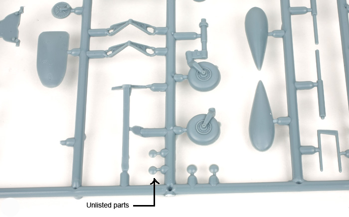
For the A-1, things are a little easier. Just follow the PCM instructions with the following notes: The headrest should have two rods or cables bracing it from behind. Again, see the attached headrest drawings. Oh, don´t forget the antenna cable going from the canopy entry point to behind the canopy, and that the antenna is taut no matter the position of the canopy. The casing ejection chutes for the inner lower wing MG17´s should be reduced as they are molded for the later MG151 cannon. Also note the separate, small bulges the PCM directions call for using on the A-3 only (part B-34) to be added to the fuselage MG access panel. Photos seem to show some A-1´s (and A-2´s) also with this bulge, and actually some A-3´s without it, though most A-1´s and A-2´s seem to have a smaller bulge. If you check the sprue, there is actually a pair of smaller bulges near the B-34 parts that are not listed. So if the photo of the aircraft you are modeling have them, or if you wish, you can add them. Also, while references say the inner gear doors should be up on the ground, several photos of A-1´s show them lowered. Again, check photos if available of the plane you are modeling, but I think you could rationalize them in either position. Again, you must find some barrels for those outer wing openings.
To model the A-2 and A-3, which are externally almost identical, things are even easier. Follow the kit instructions again, with the following notes: The headrest armor should be braced with a single rectangular tube. Landing gear indicator pins should be added to the wings (the mechanics of the retraction mechanism changed between the A-1 and the A-2). For the A-2, B-4(87 octane) fuel triangle decals should be used. For the A-3, C-3(96 octane) fuel triangles should be used. Both are on the decal sheet. Again, check photos and make a decision on the bulges on the fuselage MG access panel. A case could be made for no bulges, small bulges, or larger bulges on the photos I found. Also, according to the IPMS Stockholm article, the outer MGFF armament was sometimes removed in the field, including replacing the bulged panel with a flat one, to save weight. Otherwise, you will need to source those MGFF barrels.
A possible variant not mentioned in the instructions is for the Aa-3. This was the export version sold to Turkey. Follow the instructions for the A-3, except use MG-17s in both the fuselage and inner wing positions, and MGFF´s for the outer wings. In other words, an A-3 with the armament of the A-1. I am not sure if the shell ejection chutes were of the smaller or larger type. The FuG 25 IFF device was also removed from the radio equipment, but I don´t think this is visible on the model. Of course, you will also have to source some Turkish decals.
In conclusion, I have to give this kit very high marks. I feel it is PCM´s best kit to date for accuracy and options and fills a void in Focke-Wulf lineage.
Highly recommended!
The Fw 190A-1/2/3 is available from Pacific Coast Models directly, at http://www.pacmodels.com/.
© Ray Peterson 2010
This product is available from the following LSP sponsors
This review was published on Saturday, July 02 2011; Last modified on Wednesday, May 18 2016