
P-51D Miss Velma in 1/18 Scale - Part 4
By Jay Wheaton
Welcome back for the 4th and last installment of the 1/18 21st Century Toys Miss Velma P-51D re-build. Part 3 got us through most of the wing rebuild. Now let’s finish up. There are a few interesting projects left.
I had been looking forward to re-doing the flaps and ailerons ever since I began the wing work. Now about six months later I could finally do it. What I wanted to accomplish on the flap was first to increase the wing chord. This was done simply by increasing the chord of the flap itself. A trailing edge mismatch would occur with the wing-to-fuselage fairing at the flap’s inboard end, but it would not be seen as long as the flaps are in a deployed position. The increased chord at the flap’s outboard end would be matched by a similarly increased chord on the new aileron, but it really would not matter once again due to the flap’s deployed position. I also wanted to model a somewhat accurate flap hinge line which is biased toward the wing’s lower surface, and actually make hinge joints that the flap can rotate about. Lastly, I wanted as much realism and accuracy as possible, including the inboard end with its interesting trim.
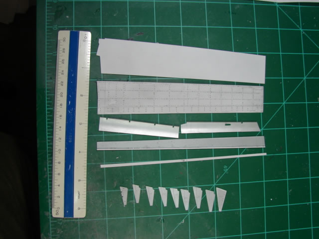
So the flaps would be 100% scratch built; a first for me. What you see above is most of the individual parts of the flap body – skin panels, spars, ribs, and leading edge panels. Not shown are three attach fittings and some small details for the inboard end. All are made of plastic sheet stock, and all were designed on the computer. I cannot stress enough how helpful this was for fit-up of the individual parts, and also fit-up when installing the flaps to the wing. The skin panels by far had the most work in them with hundreds of little drill starts to depict rivets. This work was mind numbing boring, hour upon hour, and I had to do it twice. My first set of flaps had .010 inch gauge skins – a very poor choice it turned out, and once I made the skins (including the hundreds of drill starts), spars, and ribs, and glued them all together, I found after a day or so that the skins began to sag and deform from the glue. This was a total loss of a week’s worth of work, so I threw them away and started over again using .02 inch gauge skins. I think this may have been the emotional low point in the entire build – after pushing two years of work I was seeing the finish line, and a failure like this was hard to take. It took a couple of days of letting off steam to resume the effort. This event however gave me the opportunity to correct a number of minor errors on the first set, so the second set turned out much better in many ways, and the thicker skins didn’t sag.
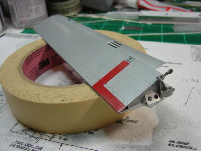
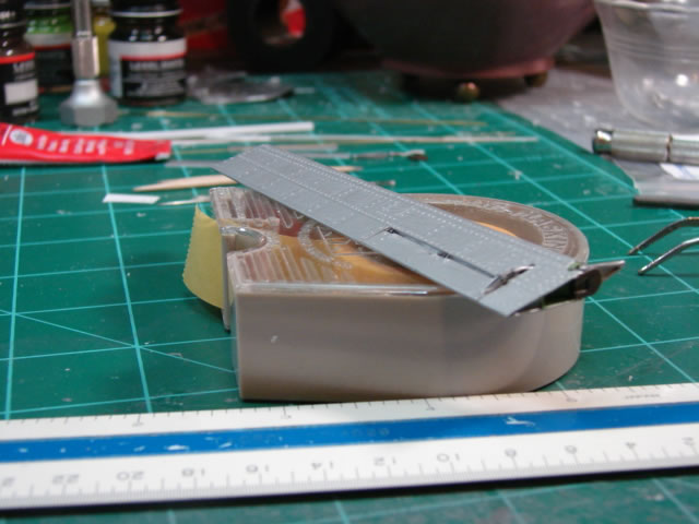
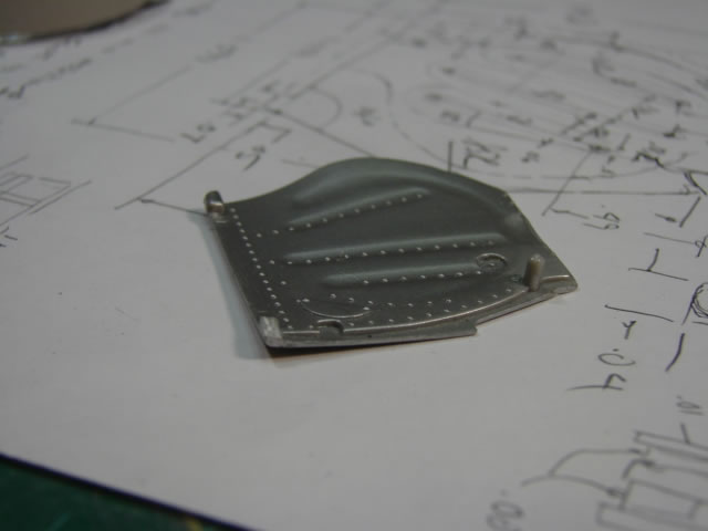
Here is one of the completed flaps on the bench so to speak. The picture shows off the seldom seen inboard end with its odd trim, end rib, diagonal stabilizing web, and inboard hinge fitting. Also note the flap drive push rod attached with a .015 wire “bolt” and nut to the upper lug of the hinge fitting. This part can be seen (sort of) so I thought it important to include it. The fitting and the rod were made of various sizes of simple plastic stock. I had visions of attaching the other end of the push rod to flap actuation components underneath the radio floor in the fuselage, but I came to my senses and forgot about it – what a challenge that would have been and you can’t really see that anyway.
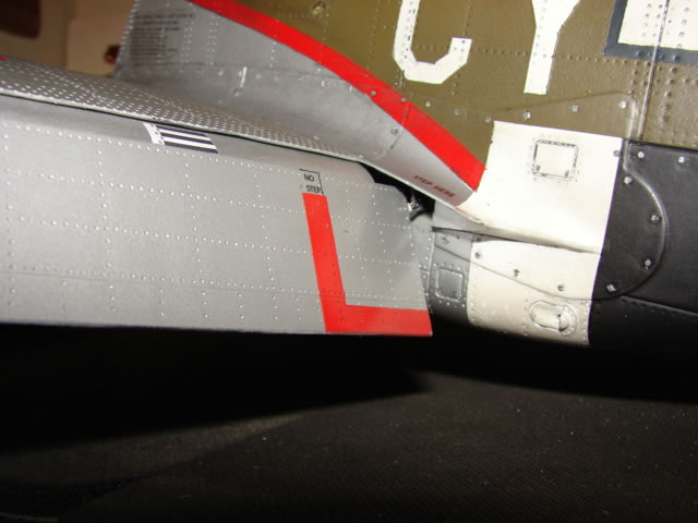
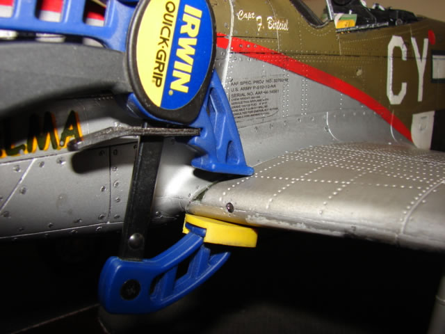
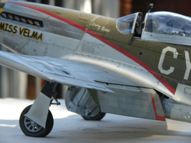
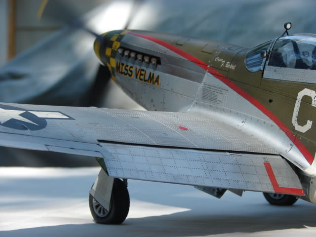
Here is the flap temp installed on the wing with the wing temp installed on the fuselage. I include this shot mostly to show off the inboard hinge fitting and pushrod under the fillet fairing (see, you can see it), and the flap LE panels that tuck under the wing upper skin panel. The LE panels were made from .005 inch thick plastic sheet, formed with a bit of a curve. The real flap has a series of former ribs under this panel to give it its shape. For this model, I didn’t make any of those ribs because you can’t see them, so the shape comes from the panels being tucked inside the lip of the wing upper panel, and deflected into shape. You can also see some homemade decals, designed per a great NAA drawing which defines all the markings on the P-51D. This flap can rotate on its hinges which are long pieces of .025 wire going through lugs on three flap hinge fittings, and matching wing hinge fittings. But the flap cannot rotate to the full up position. About 10 degrees from full up it generates an interference with the fillet fairing – but that’s OK, I knew it would. So I have to display the flaps at full down landing, or an intermediate take-off position if I want. Most of you may know that after leaving a real Mustang alone for awhile, the hydraulic pressure bleeds off and the flaps drop to full down on their own. These flaps are gigantic improvements over the 21CT parts.
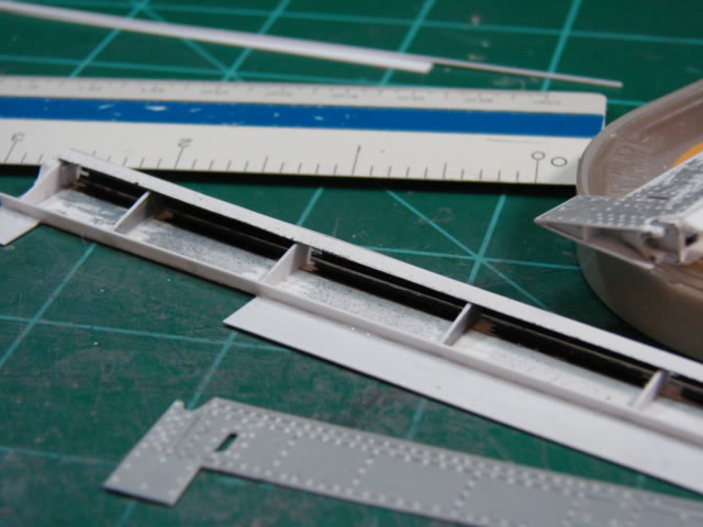
The 21CT aileron is not a separate part; it’s just part of the wing. Recall that it was removed at the split line from the wing in part 3. Also recall that I intended for the aileron to do its part in increasing the wing chord. So the new aileron would have a chord that matches the new flap on its inboard end, and matches the new wing tip fairing on its outboard end. With some experience under my belt with the flaps, I set out to scratch build the ailerons. So above you see the partially constructed units, built up similarly to the flaps, with upper and lower skins, front and rear spars, and several ribs. The aileron skins have many drill starts for skin rivets but not as many as the flaps. And this time I did not have to start over; I did it right the first time. I should note that the ailerons have tabs which have to be scratch built as well. It was a pleasure to do the ailerons and the tabs in 1/18 scale – it allowed me to add so much great detail that I just can’t do in 1/32 or 1/48.
The completed aileron is shown above with its more interesting inboard end. You can see the tab and the crooked tab control rod and its attach joint, and some clap-trap at the hinge - the aileron is actuated there. The aileron will later receive firmly attached rods extending from the leading edge at three places along its span to attach it to the wing. That way the glue won’t show.

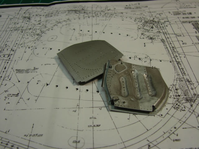
Here is another project I couldn’t wait to get my hands on. You see here the early effort on the landing gear doors (strut mounted). The part on the left on the penny is the pitiful 21CT part (RH side) – its shape is all wrong, and it’s two to three times as thin as it’s supposed to be. I did use the 21CT parts though – on the right is the built up revised LH door where the outer skin is scratch built with an accurate shape. The next layer is the 21CT part with its periphery trimmed - this part is the base of the raised inner portion of the door. And on top of that is more build-up using simple plastic sheet and then shaped. I used the 21CT part because it has about the right contour and it could force the flat build-up I was adding into about the right shape. The center part in the picture is the just-cut outer skin of the LH door, made from .015 plastic sheet.
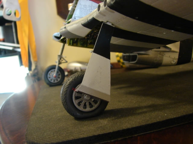
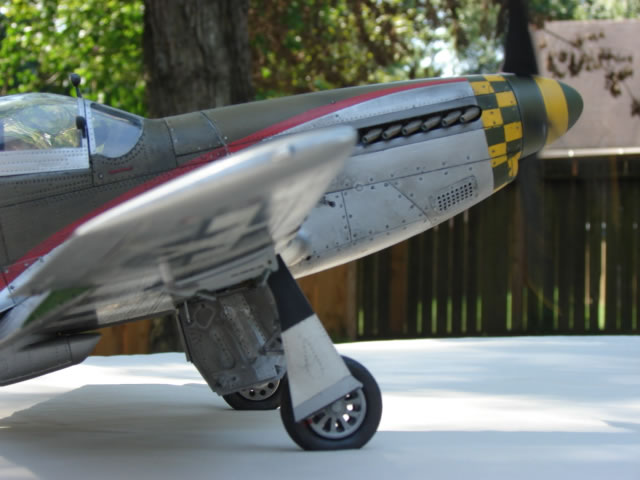
And here is what the door looks like mounted to the LG strut. I had waited a long time to see that – signature parts for the P-51.
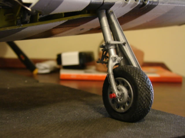
This is another shot of the LG door from the inside. It shows the links that the door is actually attached to. These I made several months before this shot was taken, out of thick sheet for the bodies, and rod for the ends. Both ends are attached with simulated hardware – bolts and nuts.
The joining of the wing to the fuselage had been looming large for quite a while now. But I had wanted to complete as much as possible on the wing while separated, knowing that after the join the model was going to much larger and more cumbersome. Now that all the miscellaneous wing work was done, it was time. This would normally be a huge milestone, but was instead kind of anticlimactic. I had dry fitted the wing so many times already, and made the necessary adjustments for it to fit well, the only difference was the glue. After the wing was installed, there were a couple of important wheel well things that needed to be completed – the wire harnesses, bomb control cables, and several hydraulic lines needed to be routed through holes in the forward cockpit floor just behind the firewall. For this, what would otherwise be next to impossible was made straight forward since the forward fuselage was not yet attached. I guess that’s a vote for my early decision to break up the fuselage.
After that work, it was time for re-attachment of the forward fuselage after it had been sitting around for the better part of two years.
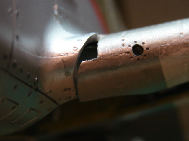
And here is what I got – a major crisis. This is what you can get when you disassemble (and more importantly saw apart) something as thoroughly as I did. The mismatch was quite serious, as it took a large amount of preload to correct it. When preloading, it put lots of stress on the forward-to-mid fuselage bond line at the firewall, and it slightly deformed the LE false spars in the wheel well. When first clamping this joint up, the forward fuselage actually popped off and I had to re-attach it using MUCH more glue and epoxy.
Above you see how the joint looks after clamping it back up, dropping in about a cubic centimeter of two part epoxy into the little sliver gap, and inserting three wire shear pins on the underside. The other side was done the same way after this side dried. I left it this way for three days per side. And after that time I held my breath and released the clamp. The joints held – but my fear is that one day I am going to go into the office and find the joints opened up and the forward fuselage popped off again. But it’s going to have to overcome shear pins is to do it.
With the fuselage and wing successfully joined, the final hooking up of systems runs in the wheel well could be done – the fuel vent lines, a drain line, and a fuel hose coming off the fuel shutoff valve on the CL bulkhead. Now THAT was a milestone.
And now the landing gear clamshell doors could be fabricated and installed. Here is one of the 21CT parts in all its glory. Just like the strut mounted doors, I used this part to shape the contour of the new door. The new parts have been built up significantly, with inner and outer skins, and filler (including the 21CT part) in between.
Above are the finished products with their excellent NAA drawing in the background. By far the hardest (and most sloppily done) part was cutting out the three depressions. I just couldn’t get them smooth. You can see the outer and inner skins, uplock hooks, and the lugs for the actuator. Barely visible are the hinge fittings that will mate with those on the CL bulkhead, using simulated bolts and nuts.
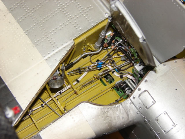
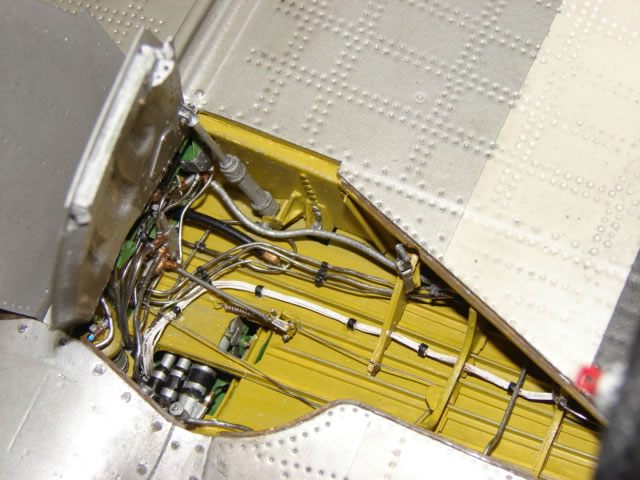
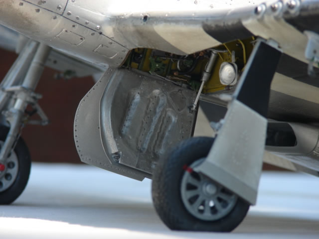
And here they are installed. Above is the complete wheel well LH side, with the doors. I have mentioned most of this stuff already, but look for the landing light with its phenolic roller, the wire harness run, radiator tubes underneath with simulated rubber couplings, and the newly installed gear door actuator rod. Buried in the far corner by the actuator is the fuel selector valve on its bracket attached to the front spar, with six hoses attached to it on copper fittings (five tanks, and the line to the engine). You can also see where the bomb control cables make a 90 degree turn up into the cockpit, right by the radiator tubes.
The complete RH side wheel well is shown above. For the first time you can see the landing gear uplock hook which attaches to the fuselage lower longeron. Many of the hydraulic lines you see here now terminate on the cockpit floor. The single black fuel hose more aft is from the fuselage tank – it has an elbow fitting on the wing skin and it passes through a hole in the CL bulkhead to the aforementioned fuel selector valve on the other side. I don’t think I ever want to detail a wheel well ever again – but I will say that at this scale, almost anything is possible.
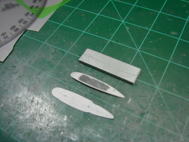
There was one last project – the bomb pylons. You can see the beginnings of this project above. The 21CT parts as usual were way off, but 21CT isn’t alone. The only accurate looking bomb pylons for the D-model I have seen are on the new 1/32 Tamiya. So of course I set out to scratch build some new ones. This was not a no-brainer. Finally after much brooding and drawing study, I decided to make a base sheet from .01 thick plastic, an intermediate body from .06 thick sheet, formed with a curve to match the wing, and then the basic body hogged out of .125 thick plastic. These three parts were computer modeled and are seen above (only scribe lines on the .125 plate).
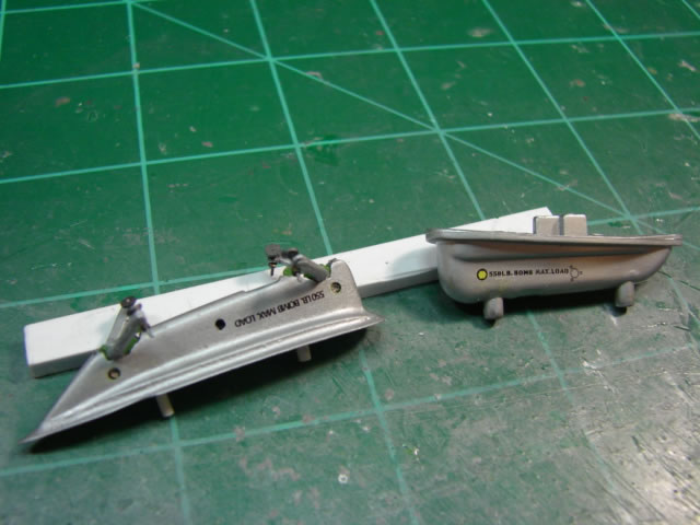
Well, it was a thrill to have these parts come out as nice as they did. The above shot compares the new parts to the old. You will also see the sway braces and threaded studs on the braces. The sway braces were pesky – they needed to be fairly thick gauge (about .04 inch), yet needed two sharp bends in them which tend to break plastic that thick (or the bent portion springs back). So instead I made two .020 pieces, bent them, and glued them together. After much trimming and filing, they turned out just fine.
The new pylons were fitted to the wing, and just like that the two-year long marathon was finished. It was at this point that a huge mishap occurred – she dropped from my modeling table to the floor after a careless act by her maker. Many pieces broke off, and the LG were bent forward. Unbelievable – after two years of no disasters, this happens the day I finish it. I won’t go into the repair effort, except to say I had to delay it until my hands quit shaking. Amazingly nothing broke that was not fairly easy to repair, and the front fuselage joint at the wing LE survived the shock. Within a couple of days she was back in shape (let’s say 97%). I would not wish such a traumatic event on any modeler.
I decided not to fit Miss Velma with droppable wing tanks – the 21CT kit comes with quite usable 75 gallon tear drop tanks, and nice 500 lb bombs too. But I have never seen a period picture of a 55th FG Mustang with these tanks. The 55th FG transitioned to P-51’s later in the war than most groups, after first using the P-38 Lightning. Also, the 20th and 78th FGs in Europe got their Mustangs late, after first using either the P-38 or the P-47 Thunderbolt. And I have never seen a period picture of a 75 gallon tank on a 20th or 78th FG Mustang. It is my understanding that later on in the war, the 75 gallon tank was increasingly replaced with the 108 gallon “paper mache” tank, made from wax impregnated paper. I have come to the conclusion that these groups exclusively used the 108 gallon tank. The kit didn’t come with this tank, and I don’t know how to scratch build one, so my Miss Velma will not have droppable tanks.
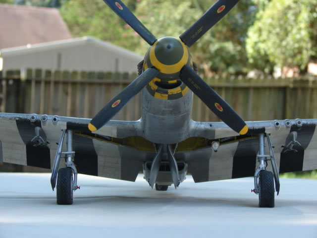
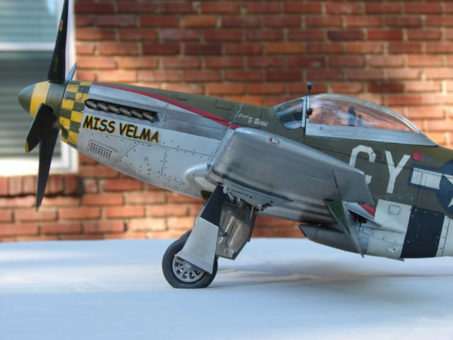
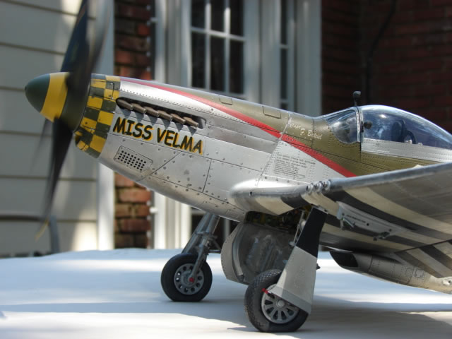
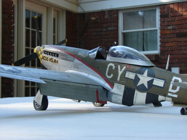
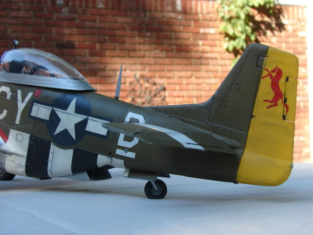
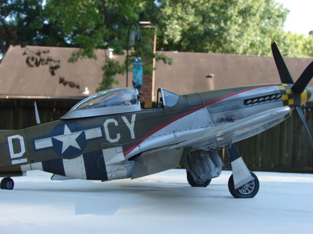
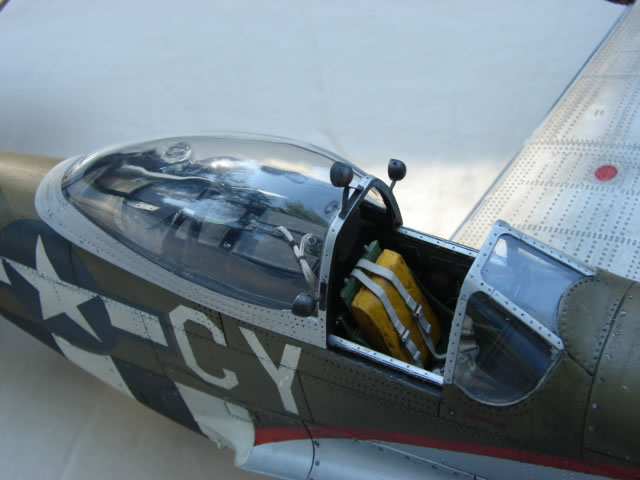
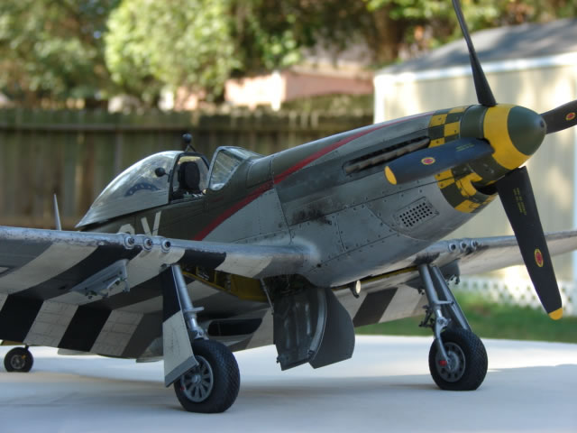
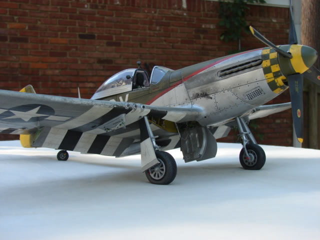
So here is what she looks like warts and all:
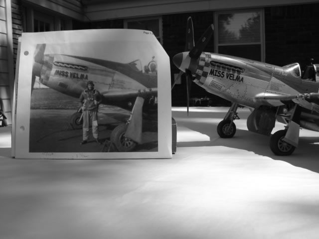
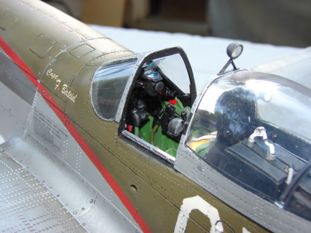
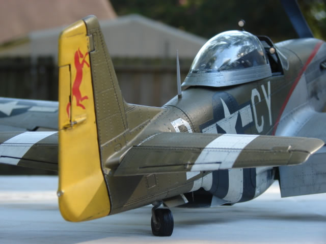
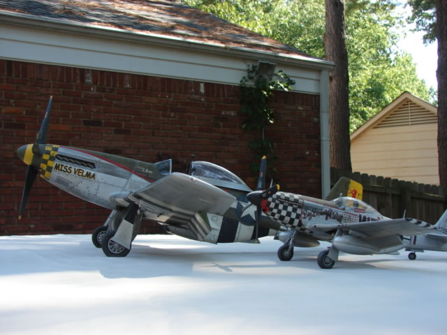
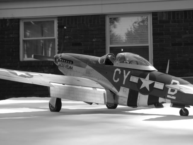
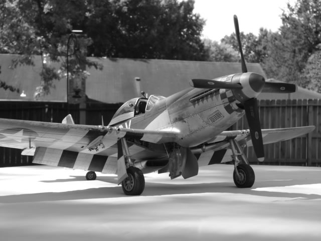
First is a B&W to compare her to a period photo with Capt Birtceil, just as a teaser. What follows is kind of a walk-around. Some show the propeller windmilling (from a nearby fan), with flaps partly up. I spent so much time and effort making sure it could do that - I needed to show it. Also included are a couple of B&Ws because I thought they looked cool, and one shot with my 1/32 Big Beautiful Doll to show how large Miss Velma is. Enjoy.

As was the case with my previous P-51 builds, I was inspired by my Uncle Hank Rudolph, recently deceased, who was a P-51 pilot (ace) in Europe with the 354th FG. If I knew what his aircraft looked like, I would have modeled it. I would like to thank the folks at the P-51 SIG for all their expertise, their willingness to share it, and their encouragement all through the project. I especially would like to thank my wife for allowing me to sequester myself in the man-hole for long periods of time to get this thing finished. I also want to thank my friend Eric for happily supplying me with some important drawings missing from my CD collection. Lastly I thank LSP for posting the articles.
Anyone nuts enough to want to try this (or any other 1/18 rebuild), if you have any questions on this re-build I welcome your e-mails. Thanks.
Part 1 | Part 2 | Part 3 | Part 4
© 2012 James M Wheaton
This article was published on Thursday, August 16 2012; Last modified on Saturday, May 14 2016