
My First F2G #57 Racing Corsair Model - Part 3: Getting Started
By Rodney Williams
We go back to January 1984 where all of this began when I joined IPMS/USA and the local IPMS club in San Jose, California. At a monthly meeting shortly thereafter I ask if any model company made a kit of the F2G Corsair. I wanted to build a couple of racers that I saw when I used to go to the annual Cleveland, Ohio National Air Races during the years of 1946-1949.
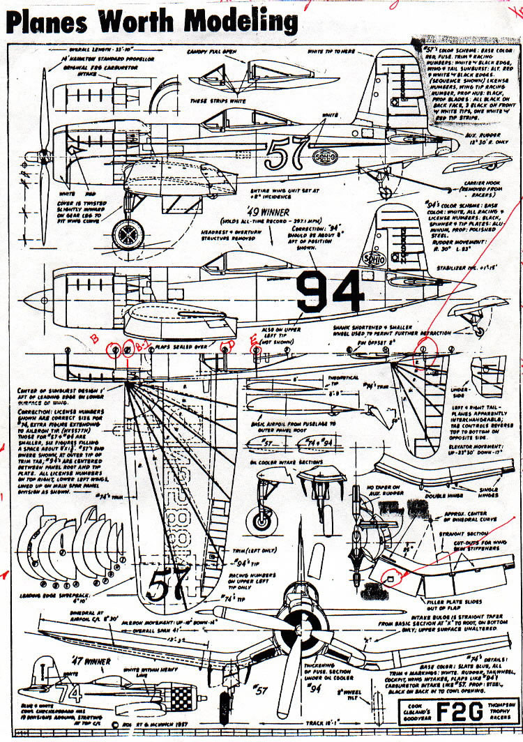
A fellow modeler by the name of Barry Bower said that there were no available kits on the market and that I would have to convert a “ready-made” kit to the F2G. Barry brought me a copy of “Planes Worth Modeling” from his book collection to our next monthly meeting. I had some 1:48 and 1:32 scale un-built F4U-1A kits in my closet, so I was ready to get started on this project.
Furthermore Barry said that I would have to carve out a new “windscreen-canopy” mold from “basswood” then “vac-u-form” the new parts.
Well, I had no idea what he was talking about because I never converted anything when it came to model building nor did I know anything about making wooden molds, including this new term of “vac-u-forming” stuff.
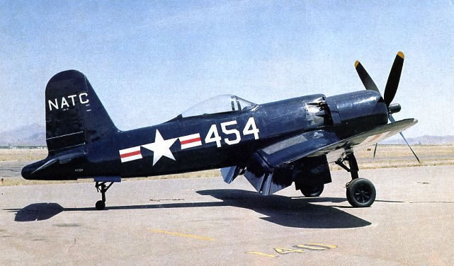
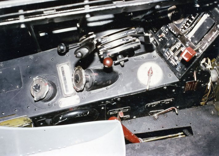
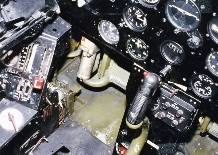
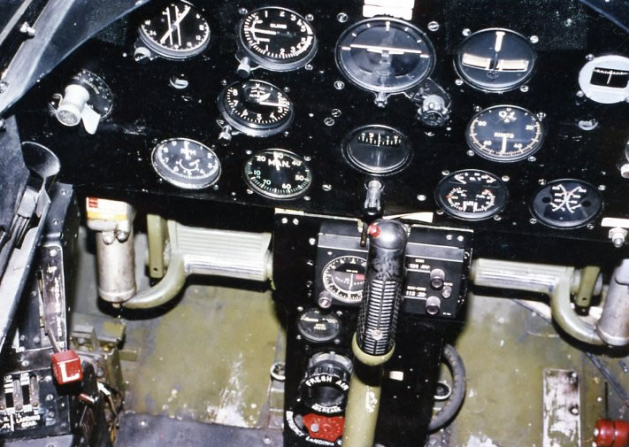
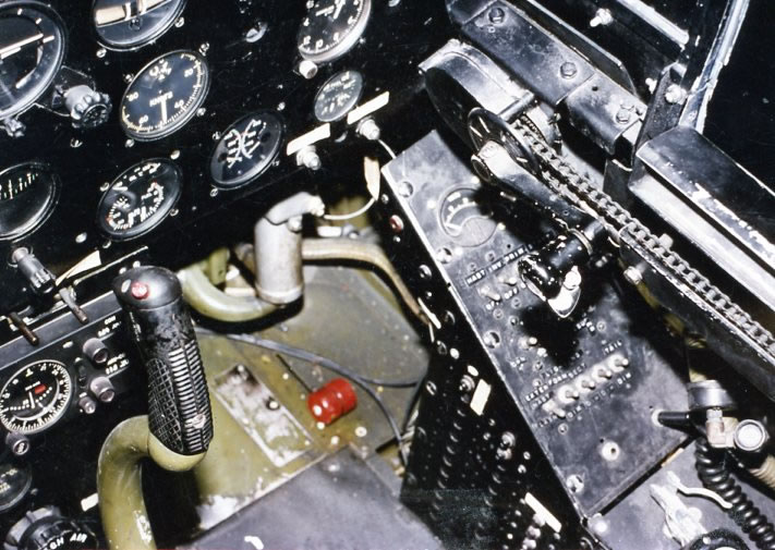
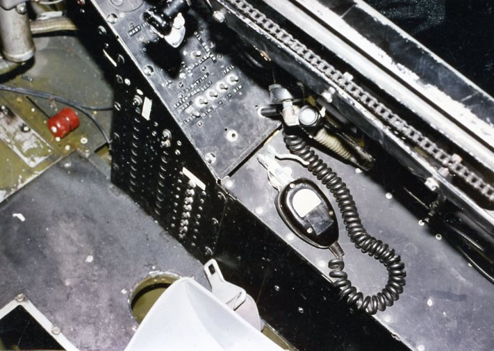
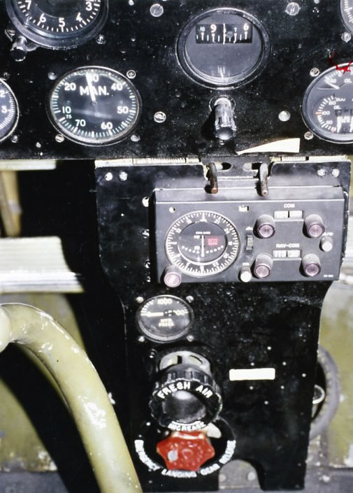
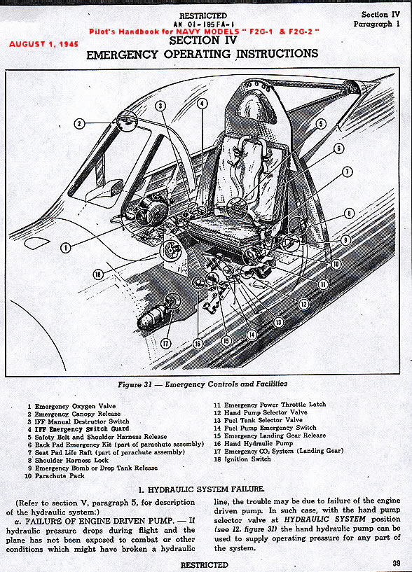
I kinda put off the project until I came back from the “Champlin Fighter Museum” in Mesa, Arizona/USA in 1986. Dough Champlin had one of three surviving F2G Corsairs in his museum. I called Doug on the phone and he gave me permission to come down and take all the photos that I needed and any measurements that were necessary to build my model. He had Charlie Ayres take some color photos of the cockpit.
SOME PRE-BUILDING WORK
In the 1950s I use to draw ¼ scale house plans and built scale models of the real home for said client. I took the plans that Barry gave me down to “San Jose Blue Print” who enlarged my drawing to 1:48 and 1:32 scales. Now I could build the kit in either scale.
I scaled up a side and top view drawing of the F2G’s windscreen-canopy. Shortly thereafter I went to “D & J Hobby’s” over in Campbell, CA and ask someone in the crafts department if they had any “Bass” wood? Lo and behold the lady said yes and directed me to the section of the store where they carried a variety of wood building products.
I ask another employee by the name of Al Ernat if they had any “Vac-U-Form” machines and the special type of plastic that you needed to use to “VAC” a canopy and windscreen? Al said that I would have to make my own “vac” box, including the plastic holder and buy a new toaster to heat the plastic. I was informed not to use our household toaster due to the fact that at times some particles of bread may be vented up onto your plastic which will be embedded into it when you push down your heated plastic onto you mold.
A fellow modeler at the local “Fremont Hornets” model club up in Fremont, CA gave me a drawing of a “vac-box” and showed me how to make it.
MODEL CONSTRUCTION
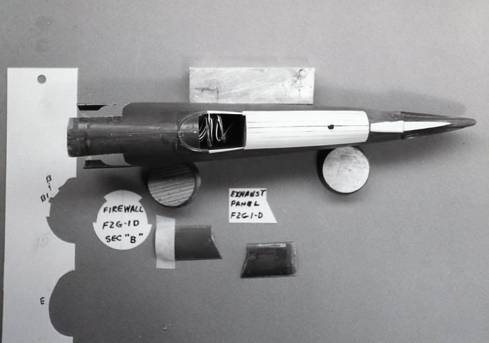
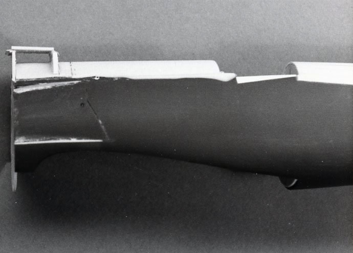
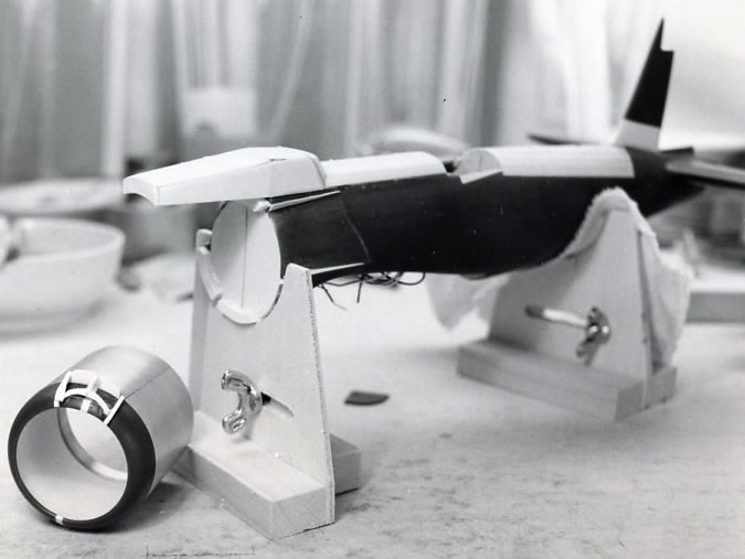
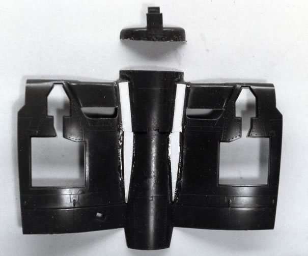
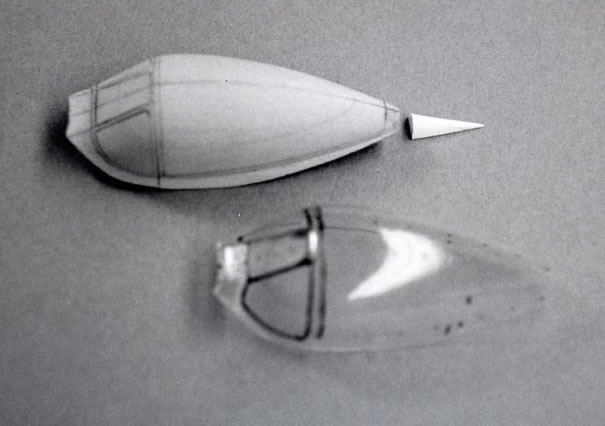
My first photo shows a side view of my fuselage cut-apart with some bulkheads glued in, including some wires attached to some “LEDs”. I read a story on “How To” buy and install these little lights in your model. I had to abandon this idea as Cook removed the navigation lights on his #57 racer.
I taped the cut down fuselage together and then dry fit in the kits cockpit tub from below where the wings would fit. With some minor adjustment, I knew that my new scratch-built cockpit would fit up in the model OK.
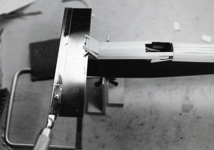
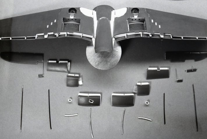
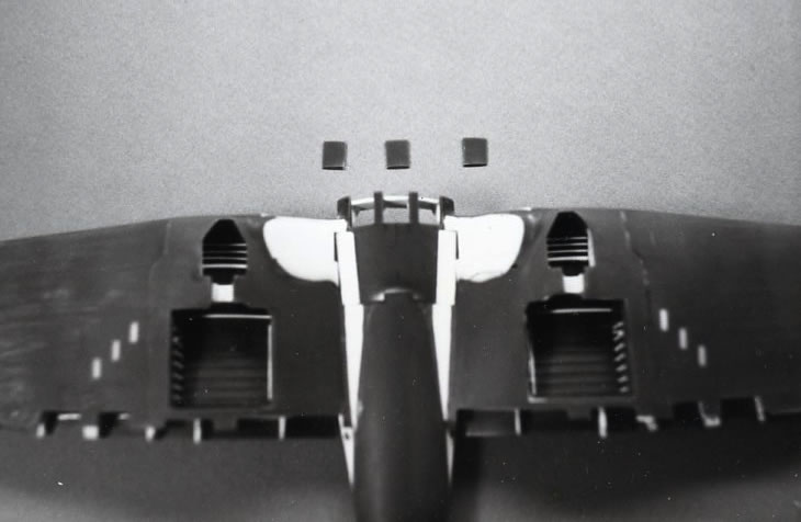
The next few photos shows how I cut apart the front section of the fuselage and built in the exhaust area, including the front top and the aft rear deck of the fuselage. These modifications had to conform to the F2G side-view drawing.
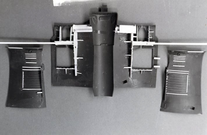
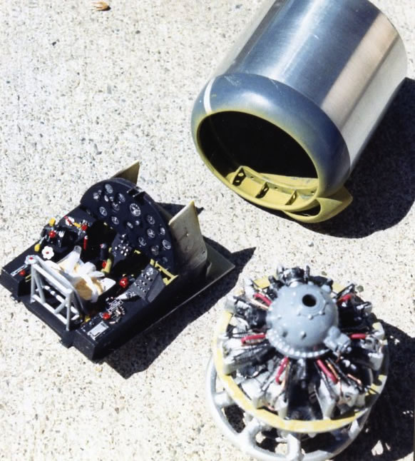
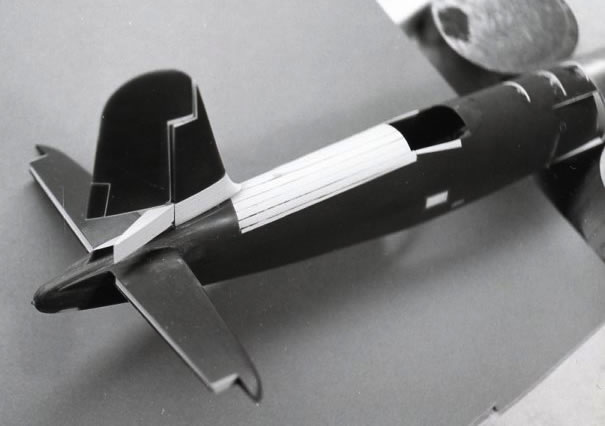
My friend Stanley worked at a local aluminum tube company in Milpitas, CA and he got me the right size of aluminum tubing so I could make my cowling out of it. I used the kit's cowling ring and just added some extra styrene card stock to fill in the void as the front of the F2G cowling did not taper inward like the “1-A” cowling did.
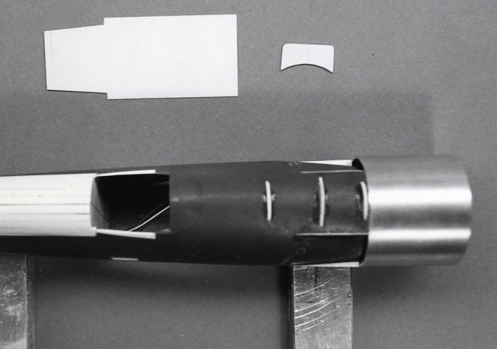
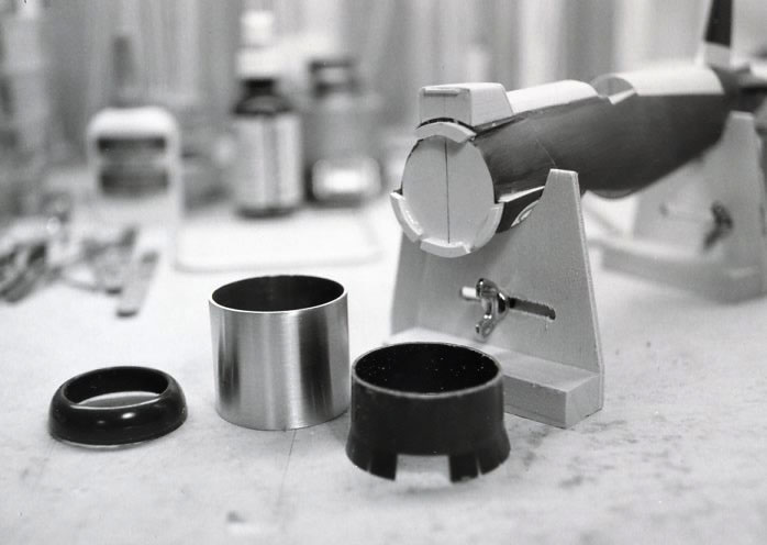
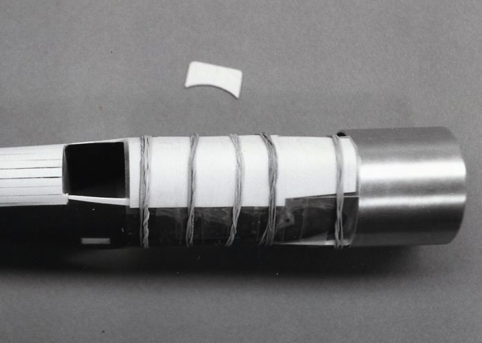
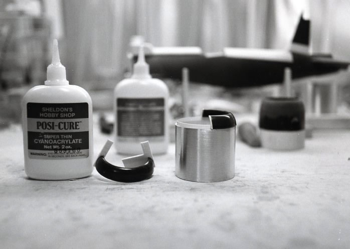
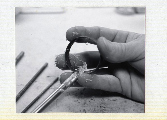
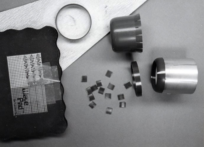
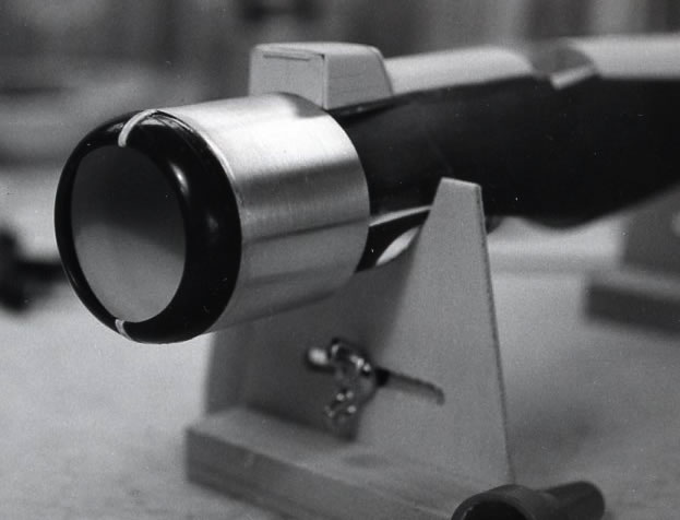
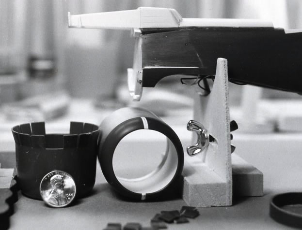
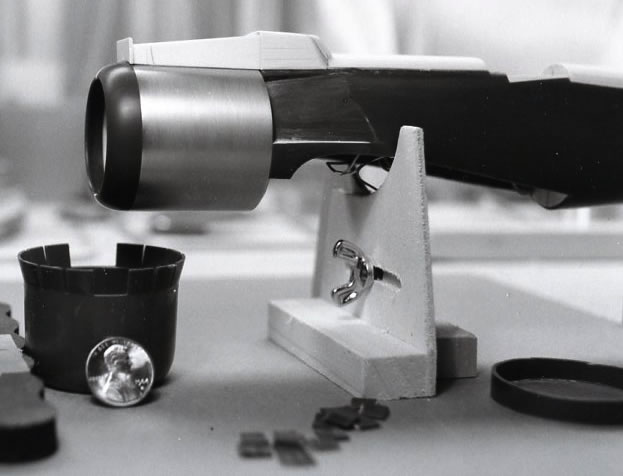
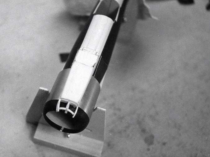
The cowling was temporarily glued to the firewall with white glue so I could build on the extended air scoop for racer #57. The “intake” was built up in 3 sections. (One was built on the fuselage while another one was built on top of the aluminum cowling and the front section was built on the speed ring. I used .020” .040” and .060” thick Evergreen card stock. I used super-glue for my adhesive material. A bit of sanding was necessary.
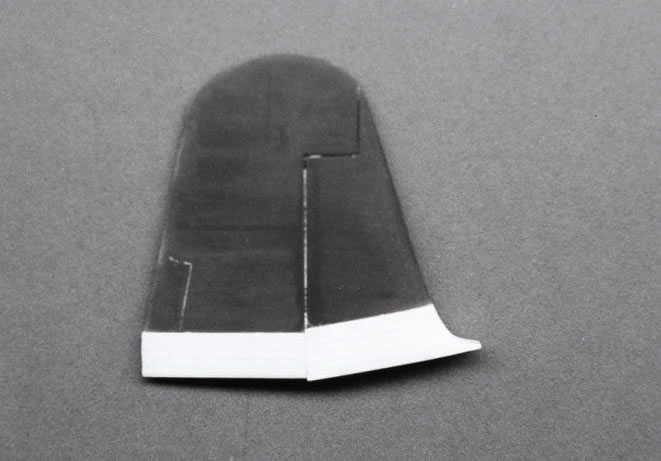
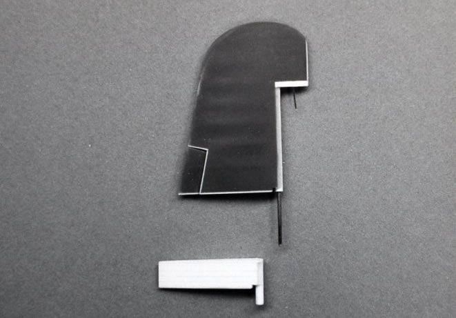
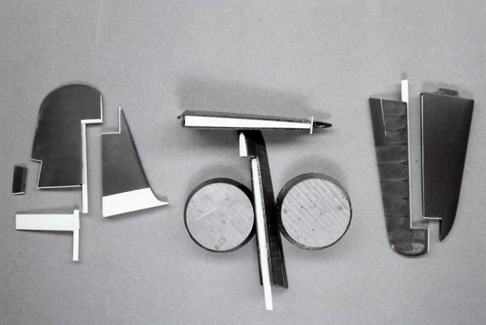
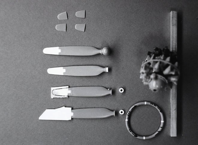
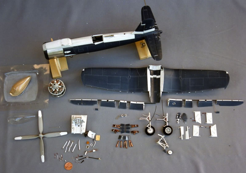
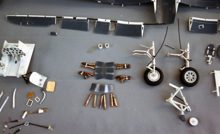
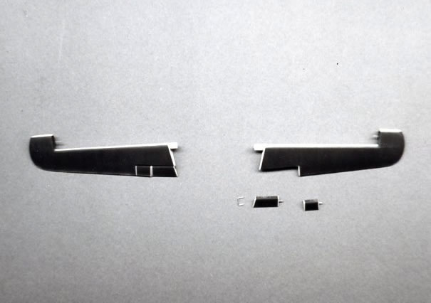
It’s time to revise the fin-rudder, including the stabilizers and elevators. The rudder and elevators were cut apart so I could off set them if desired. The auxiliary rudder measured 11.5 inches tall so I crafted my new one to match it. My photo shows that I built up the fin to mate up with the new auxiliary rudder. I built in the trim tabs on the rudder including the 4 tabs on the elevators.
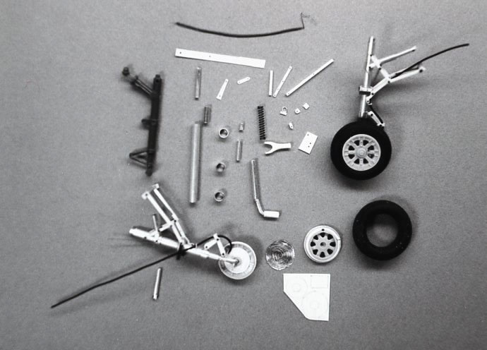
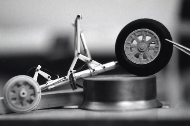
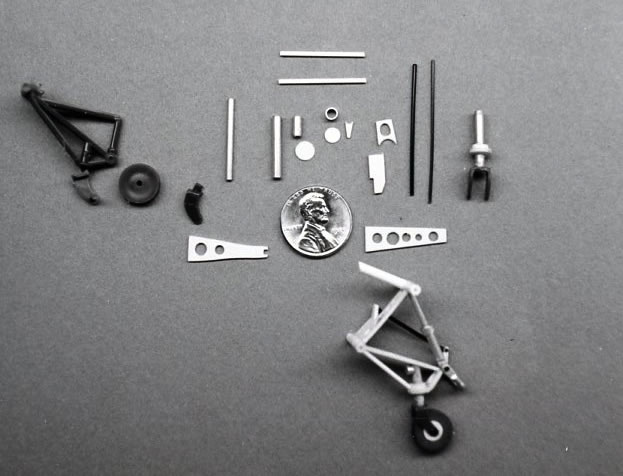
Next came my new task of scratch-building all three landing gears. I used aluminum tubing and some plastic. I had three F6F Hellcat kits so I used the real rubber diamond tread tires on my Corsair model.
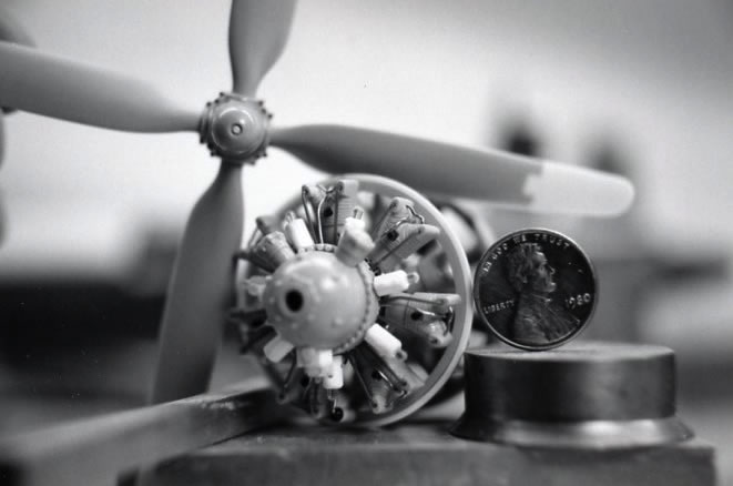
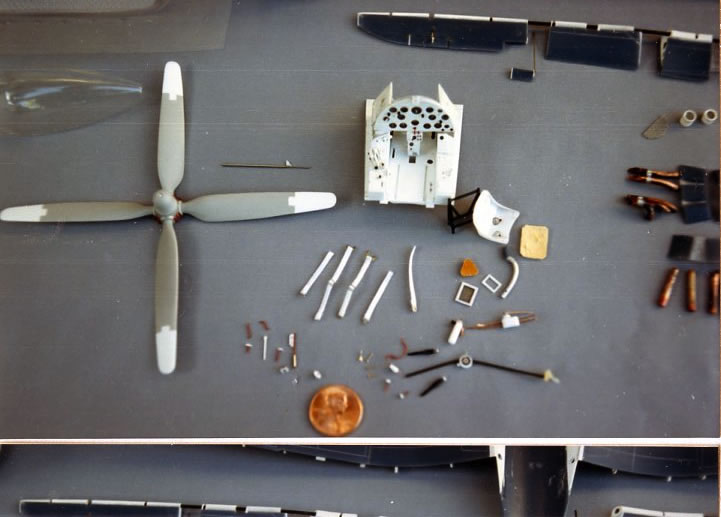
I used 2 of the engines from the Hellcat kit to make my new P&W R-4360-2 F2G engine as it had 7 cylinders in 4 banks including 7 magnetos in front of the cylinders. I made two rows of cylinders’ as you really can’t see all of them once the cowling is on the model.
I revised two of the Hellcat kit props as I needed a 14’ 0” diameter four blade prop and I built the bracing that goes inside of the front section of the cowling.
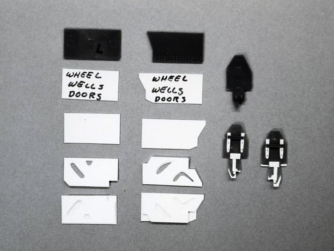
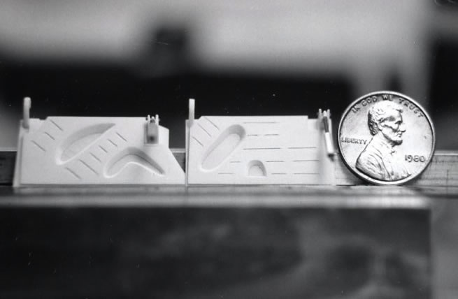
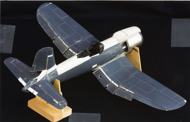
The wings were my next project, so I cut loose the flaps and ailerons as I wanted to drop the flaps and offset the ailerons. New main gear doors were built including the two tail wheel doors. The wing air inlets had to be revised to their new shape, so it was fun building in these items. Since there were no running lights, these areas were filled in and sanded smooth. There was next to nothing in the wheel wells so I built in the necessary items so it would look realistic.
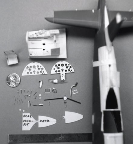
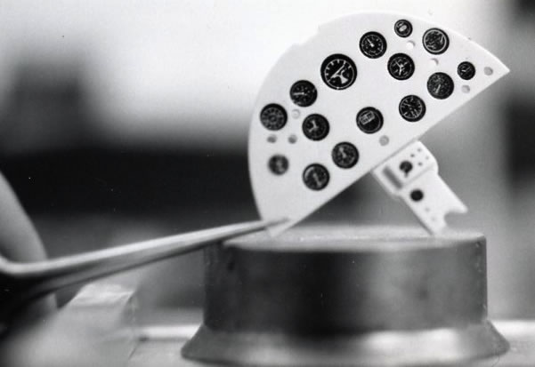
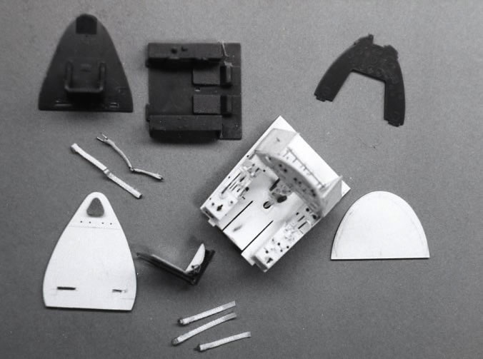
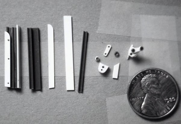
I had purchase Waldron’s punch and die sets, including their instrument dials and seat belt buckle kits. With Charlie’s cockpit photos I laid out my instrument panel and punched in the holes for the dials and then carefully punched out the dials and dry fit them into my instrument panel.
Once the front of the instrument panel was painted, I glued the backing plate in place with Future Floor Wax, and then installed my dials using more future. After it dried, I added lots more future to the face of each dial so it would look like I had a glass cover over them.
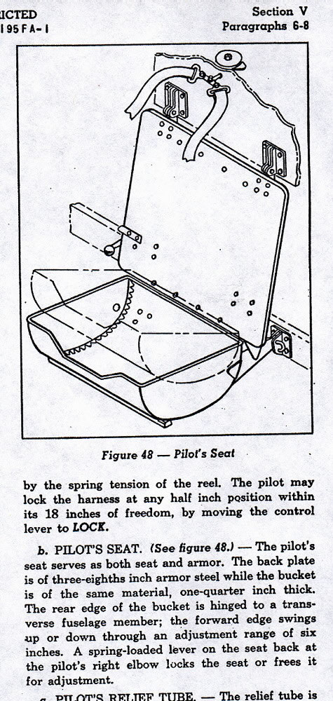
My biggest project was now at hand, “Building my first scratch-built cockpit”. Again using Charlie’s photos of “454” I cut and fit the styrene card stock until all the parts fit onto the floor of the “cockpit tub” which was constantly dry fit up into the cockpit area. I made patterns of my parts as I knew one day down the road that I was going to make more F2G models.
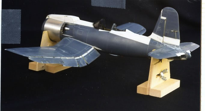
It was “Spring-Time” 1987 and my model was together and ready to be painted. I doubled checked everything that I could think of so I was sure I had accomplished my goal of building my first accurate F2G model.
In my final story I will relate the painting process, which gave me some major problems for this novice model builder.
Part 1 | Part 2 | Part 3 | Part 4
© 2012 Rodney J. Williams
This article was published on Thursday, July 26 2012; Last modified on Saturday, May 14 2016