
I.D. Models 1/32 F-84F Thunderstreak, Italian Air Force
By Luca Pennacchietti
The F-84F Thunderstreak is the arrow wing development of the F-84E that so distinguished itself in the Korean War, but the chronic lack of engine power limited the ambitions of the project, although, at low level, this aircraft could well rival the more popular F-100 and F-86. The only operational use (by the French) of the F-84F was in the Suez crisis, where the plane behaved just fine.
Although performance was not exceptional, the plane was adopted by many European nations including Norway, Germany, France, Belgium, The Netherlands, Greece, Turkey and Italy, where it served from 1956 to 1972. The F-84F isn’t very successful in the modeling world and all existing 1:72 and 1:48 kits show some glitches. Models of this aircraft are rarely seen in contests.
Years ago I had the chance to buy a 1:32 vacuform made by I.D.Models, and when I received it I discovered some flaws and simplicity of shape, complete lack of detail and those which were present were wrong. No metal landing gears, no decals and a nicely yellowed canopy...
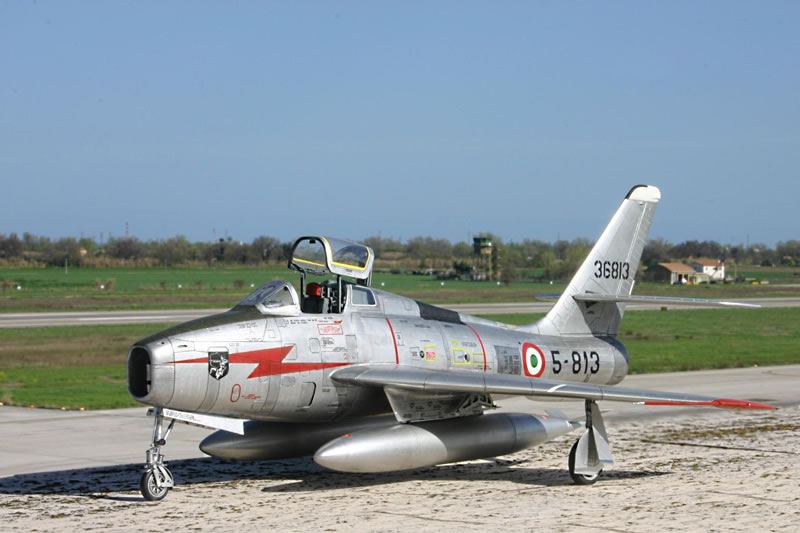
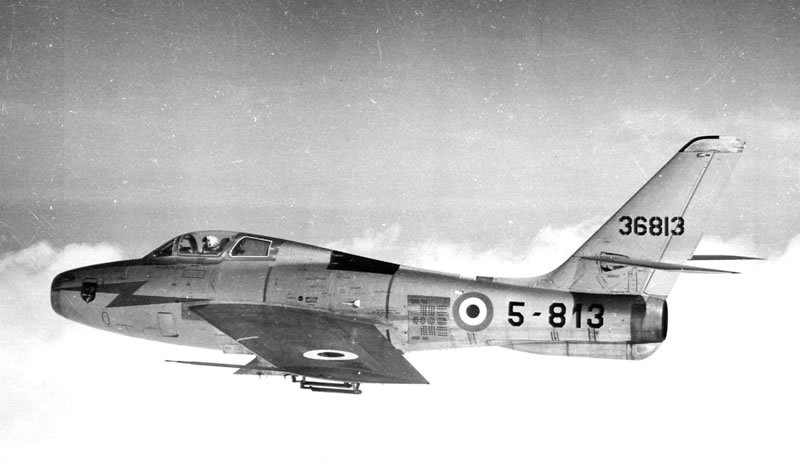
Eager to enter some modeling contests, I decided to do something significant and I chose the F-84F-66RE, U.S. serial 53-6813, individual number 5-813 of the 5th Wing (5a Aerobrigata) of the Italian Air Force based at Rimini (Italy), as it appeared in the late '50s/early ‘60s.
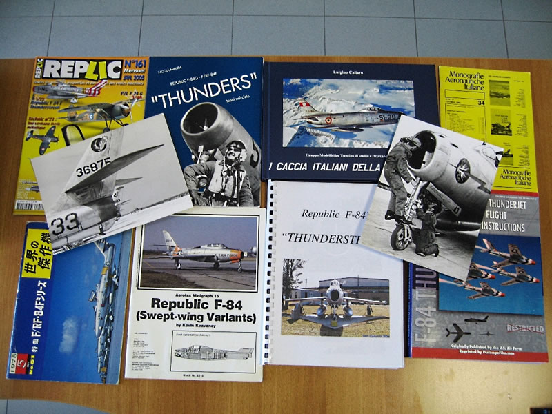
The first inevitable duty for a modeler is to check the correspondence of the model with the real plane, and this applies not only to vacuform models. And this check must be done through scale drawings and especially through the photos of the real aircraft, more than ever today that we may also use Internet. In fact, for any of the models I have built or I have done researches on recently, there is NO good scale plan, even in well known publications, and that must be held in high regard. Never trust people who say "I checked the model with the drawings”. Just compare two scale plans of the same aircraft from two different sources to realize that they are different from each other and in some cases both are wrong!
After checking the pics, the best scale plans I've found for this aircraft are contained in the instructions of Daco decals. They correctly depict a late production aircraft, with taller tail, fully movable tailerons, larger airbrakes and ventral parabrake.
Though still showing a not precise arrangement of panels under the cockpit, these drawings are almost perfect including the wings where all other plans are wrong. Moreover, instructions are very helpful in deciphering the original stencils.
THE WORK BEGINS
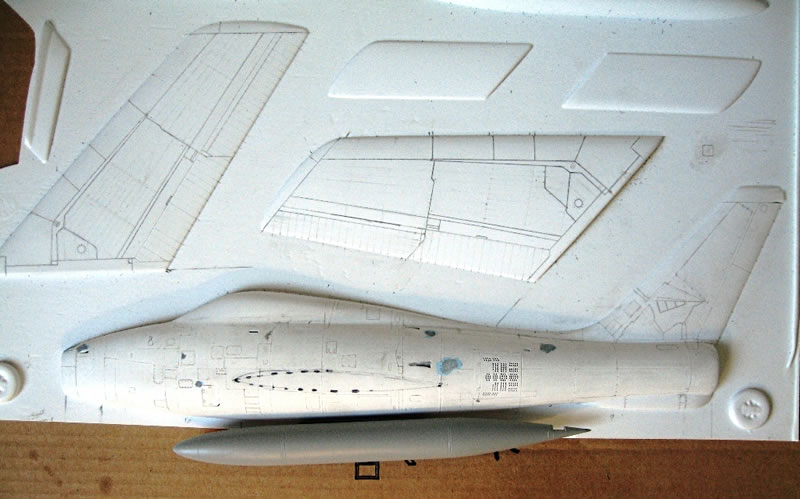
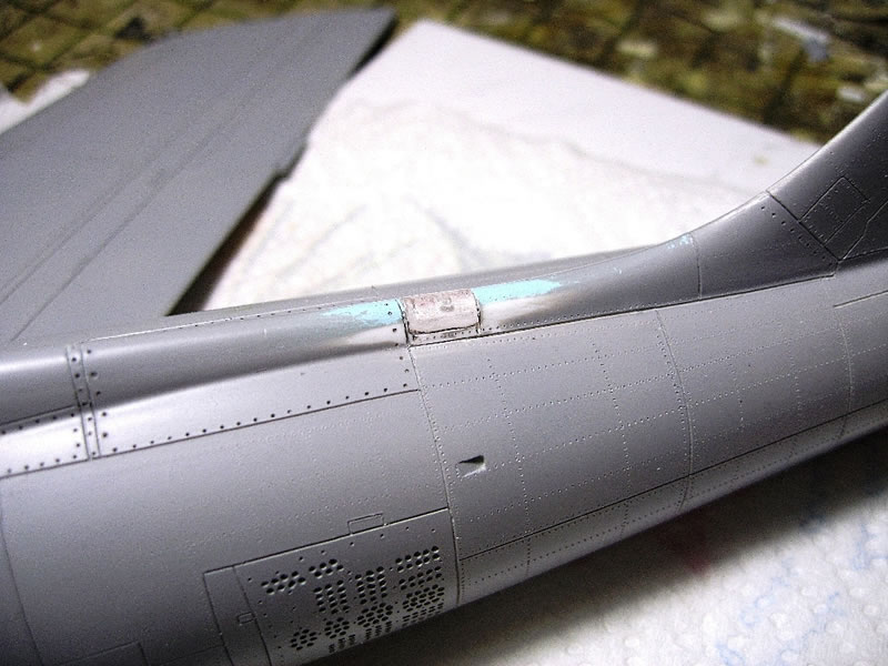
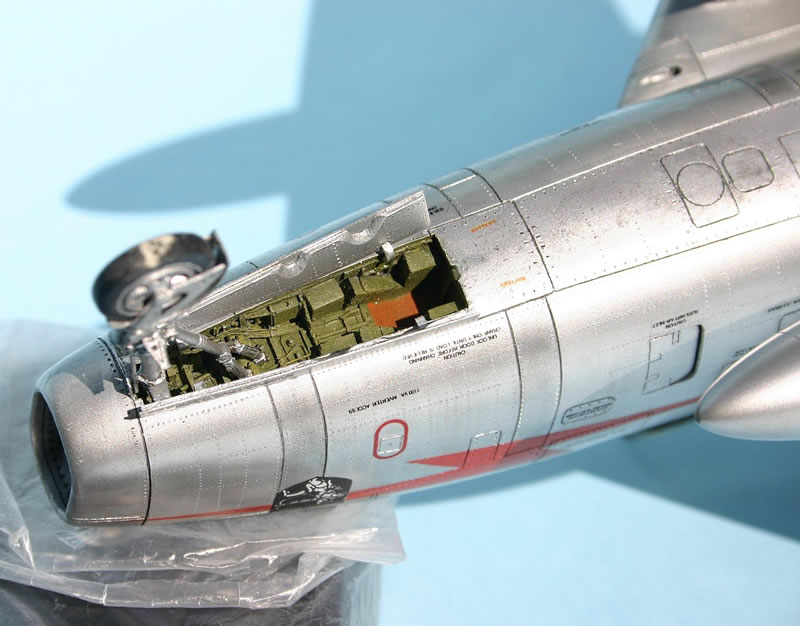
I will not dwell on how to scribe and go riveting the model. There are various suitable tools on the market. Just remember that the plane had rivets of different spacing according to the different areas and I simulate some larger screws of removable panels by using a very small drill bit. I paid much attention to take good measures of where to place the junctions between the panels to avoid asymmetries between left and right fuselage halves. I also proceeded to open various auxiliary air intakes on the fuselage. The large ones, placed beneath the cockpit to increase the airflow to the engine, were simply cut on 3 sides with a sharp blade and then gently folded inside. Each airbrake has 178 lightening holes performed individually with a small drill bit ... No structure was built inside, due to the fact that it’s almost impossible to see it on the finished model.
Photos of disassembled airframes found on the Internet clarified the internal structure of the aircraft, and led me to create a backbone of plastic (reinforced with wood) that I called "the fish", to ensure rigidity and alignment of intake trunks, cockpit, nose gear compartment and exhaust.
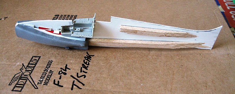
A great concern was how to reproduce the two trunks of the intake since their upper and inner faces are flat while the outer face is curved. I managed to create two ducts made of sponge rubber, the one with small and compact cells made by Gütermann Company, available in fine arts and hobby stores. It was easy to give it a correct shape and to glue into place by super glue.


THE COCKPIT
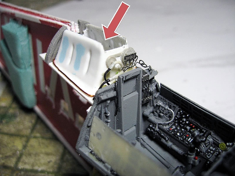
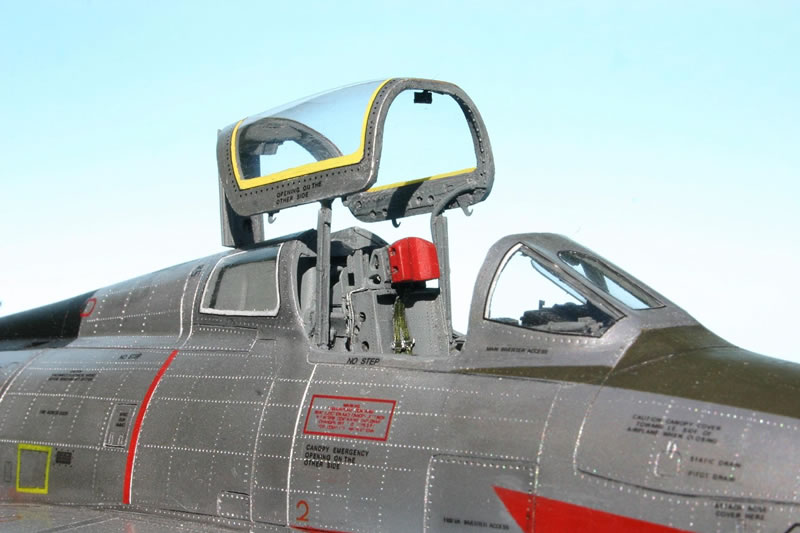
The hub of an F-4 was used as a starting point for the cockpit. The throttle has been rebuilt, as the control stick, rudder pedals and all the structure behind and above the instrument panel, housing the computerized tracking device, the closest possible to Republic’s technical drawings.


As for the dashboard, thanks to Luca Orsini from Pisa, I had access to a color photo of a perfectly restored instrument panel, without perspective distortion. I just had to print it to scale and I got the most correct scale instrument panel of the world!
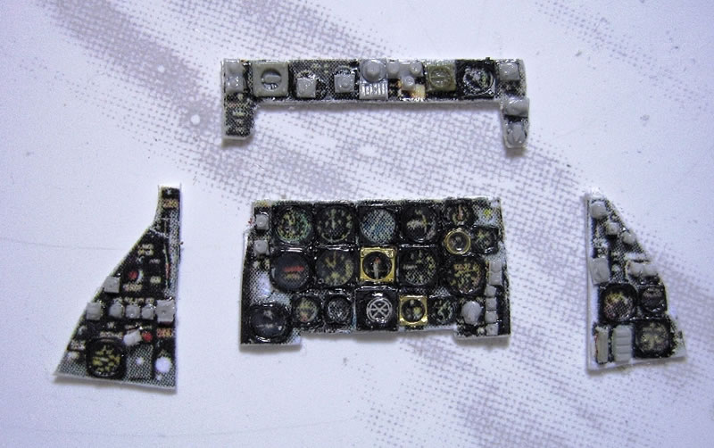
Along the production blocks, color and layout of instrument panel has changed 3 times. Initially the entire cockpit was black, including the canopy frames and instrument panel. Then with the second layout, gray FS36231 was introduced. The third instruments layout was still different though still in gray.


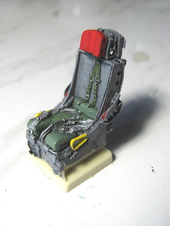
Republic, that produced the F-84, later built the F-105 and has also produced ejection seats for both aircraft. They are extremely similar, marking an evolution of the same basic model, and fortunately in 1:32 there’s a wonderful resin ejection seat for the F-105, (# 32067 by Quickboost) to start from. Along the operational life of the aircraft, the safety belts were changed three times and the ones on the seat of the F-105 are similar to those seen on the most recent F-84s.
THE 'LIQUID' SPAR
Being the wings long just enough to meet the scale wingspan and being the mating surface to the fuselage very small, it seemed impossible to make a so large vacuform model robust enough that it can be handled safely without crushing the fuselage and the wings.
I decided to discard the idea of a passing spar. There was no certainty to make one or more spars with the correct dihedral and to make them interact properly with the swept wing and the large main landing gear wells so close to the fuselage. I decided to close the fuselage and glue the wing into correct position with no internal reinforcement accepting the temporary weakness of the whole till the glue was set, and to create the internal structure that gives strength only afterwards.
My idea was to create a 'pool', i.e. an open-air, leak-proof compartment, which would pass from wing to wing through the fuselage and the 'fish', to be filled with resin from atop. When the resin hardens, it takes the correct form imposed by the wings and then gives strength to the plastic parts. I would have poured the resin through the empty area rear of the cockpit.
Inside the fuselage, I created two halves of the 'pool' using scraps of a mat for gym or camping. After having determined the right shape and size, I glued together the different pieces to form the base and walls on each fuselage half.


Then focus shifted to the wings. The landing gear well walls were made by many pieces of resin, thin plastic sheets and the inevitable rods.


The wing root to be flooded with resin from the fuselage was bordered with strips of adhesive foam, the kind that is used to seal house windows, down to the inner face of the wheel well. The foam is soft and when you mate the two wing halves it is automatically pressed down to the shape of the interior of the wing. The resin, flooding through openings cut into the plastic at the root of the wing, would reach these walls and create an internal structure that covers 2 / 3 of the model’s span and provides a considerable strength to the whole.
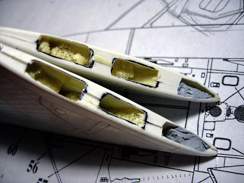
Other foam stripes are attached inside the wing toward the tip, and serve a similar purpose. Once the top and bottom halves of the wing are mated and before gluing the wings to the fuselage, I poured the resin into the root of the wing along the wing leading edge down to the wing tip and then turning back along the trailing edge up to the roots. This resin does not completely fill the wing but just ‘washes’ their inner surfaces and the foam blocks letting them become rock hard inner structures.
I checked the compatibility of the two halves of the fuselage and the internal structure by some dry-fit tests, aided by powerful rubber bands. With proper injection of super glue from outside I got the correct alignment and then I 'settled' the weld with the Tenax R glue. The fuselage halves were glued not directly to each other, but each to the inner 'fish'. With an appropriate bead reinforcement and support, I got a doubling of the bonding surface, for the benefit of the model’s strength.


Once the fuselage was glued, I cut out the openings and slipped the wings into the fuselage, gluing them into the correct dihedral and sealing the cutout with some Mr. Surfacer. After all gluing and filling was settled, I poured small quantities of resin at a time inside the aircraft not to develop too much heat and not to risk potentially disastrous leaks, until the pool was full.
My 'invention' worked even better than expected. I can hold the model by a wing and shake violently without any structural risk. The resin spar is now a structure up to about 2 cm thick that is perfectly adapted to the imposed wings dihedral.
CANOPY, LANDING GEARS AND OTHER DETAILS
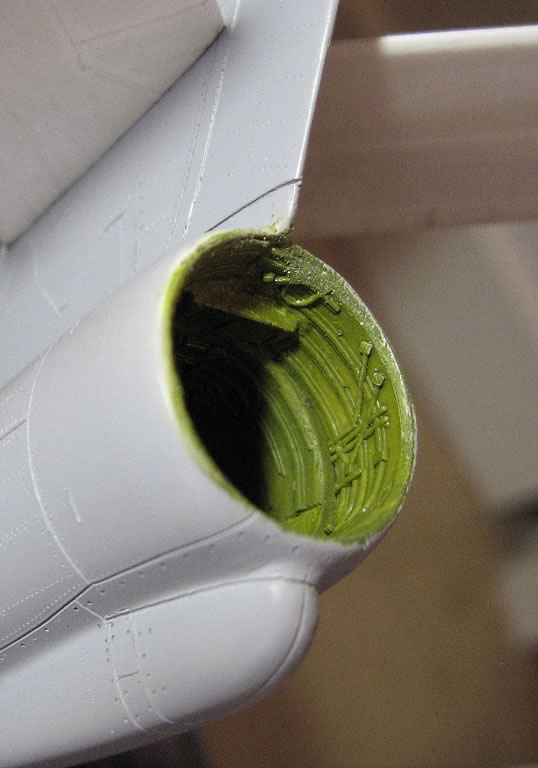
I brushed the interior of the air intake with several coats of Gunze Mr.Surfacer to have a smooth finish. The parabrake ventral fairing was made longer using half rocket launcher pod.
In the meanwhile, I got some acetate copies of the original kit canopy which was absolutely useless. These were dipped in Future and then let drain and dry slowly. The treatment has made the acetate exceptionally bright and clear. I immediately proceeded to close the opening from which I poured the resin and to cut away all areas equivalent to the glass canopy, windshield panes and rear windows from the fuselage plastic, leaving only the frames. Indeed, even before closing the fuselage, I realized that I could never use the whole vacuform canopy without an internal structure. The plastic was too thin and would not withstand any stress. So I decided to apply the transparent sections over the fuselage and the frames after having painted the inner structure gray FS36231.


After several dry-fit tests to determine if all items were properly designed and finished, I proceeded to mask the cockpit and spray the entire model with Gunze Mr. Surfacer diluted with polyurethane thinner.


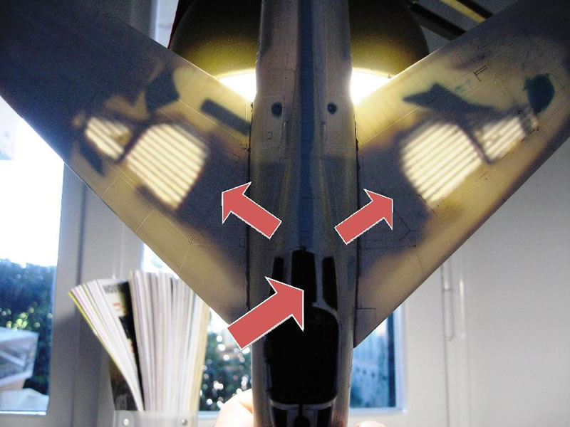
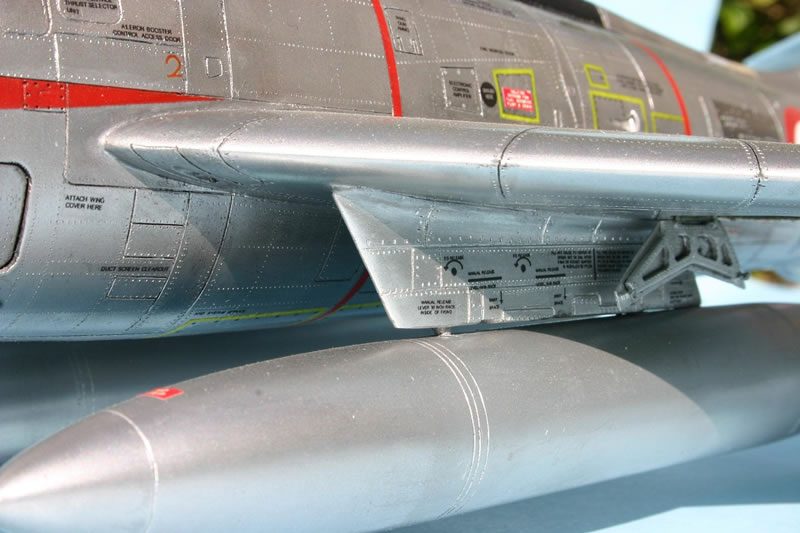
On the lower side of the wings, next to the fuselage, I proceeded to open the slits of the two wing guns, with their chimney for shells and plates to prevent the shells to collide the airbrakes.
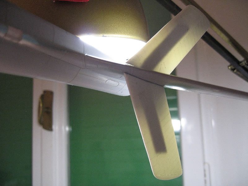
I added ‘trim tabs’ to the wings and rudder while horizontal tail planes could instead receive a simple plastic spar as they have no dihedral.
 LP_F-84_043
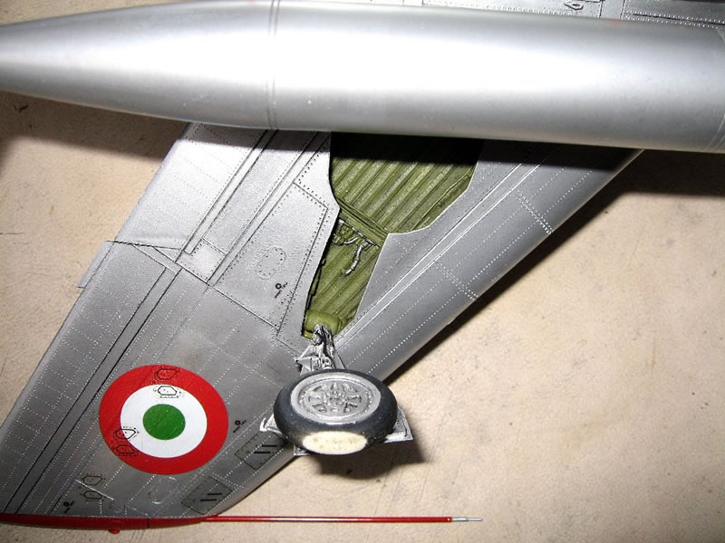
The fuselage is now ready for the painting phase. I then turned to the landing gears.
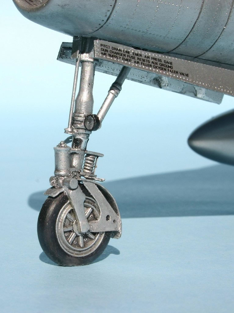
The main doors were made of a sandwich of plastic sheets of different thickness and by adding metal details. The main legs come from the white metal ones for the F-105 (still him!) in 1:48. The F-105’s landing gear is so tall that I had to shorten the one in 1:48 to size the one in 1:32!
One of the things I didn’t find in any of the sources, but is clear out of a careful examination of the photos, is that the rims of the wheels have an asymmetrical design and are bond to the landing gear legs. They do not rotate with the tire, which is instead mounted only on a thin metal outer rotating ring. So you cannot glue the wheel of an F-84 model in a random position!
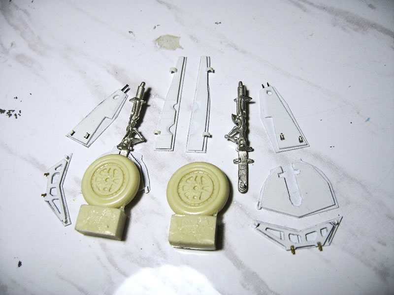
The front landing gear leg is a mix of pieces from different sources, with the fender made by thin plastic sheet. The nose wheel had at least two different rim designs during the operational life of the aircraft and the wheel I used was obtained from the F4D Skyray by Lindberg.


PAINTING AND FINISHING
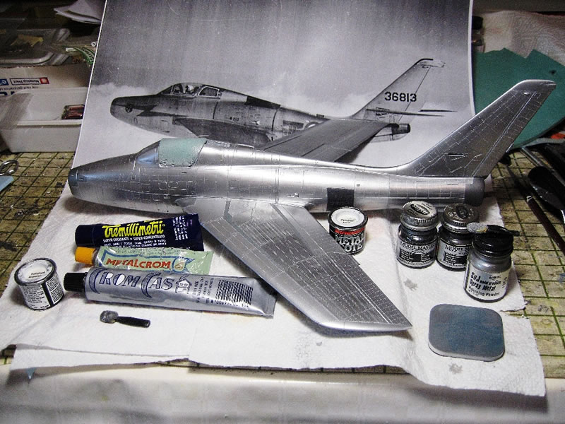
I painted the whole model with the more modest and perhaps oldest 'Metalizer’ paint, namely 'Polished Aluminium' of Humbrol. No Alclad or similar, which I tried in the past and I have not liked. I better preferred a more robust paint, capable of accepting the following phases without causing too much trouble.
'Polished Steel' still by Humbrol was used on the airbrakes while panels around the intake, exhaust, root of the wings and along the wing spars were painted with Testors’ 'Steel' Metalizer. The different reflections of aluminum were obtained by polishing each panel with Tremillimetri, Metalcrom and Cromcasa polishing pastes of Italian brands (similar products are available in almost any hardware store all over the world). Each panel has been masked and gently polished. Only a very limited amount of SNJ powder has been used on a few of them.
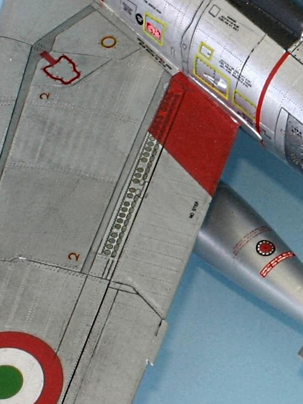
On the wings, there are series of perforated spoilers. In fact, half of the holes are circular and half elliptical, all 'closed' by a dense wire mesh, unattainable even in this large scale. It was unreasonable to drill the holes all perfectly lined up, of the correct form, all equal and realistic. With a perhaps unorthodox reproduction technique, I draw these spoilers on the computer, and then printed them on clear decal. Even on the real aircraft there’s a lack of depth, and I preferred a ‘flat’ reproduction with absolute precision of the drawing and sincerely believe that in this case I choose the best solution.
The white and orange seals on the canopy were reproduced by acrylic paint and a good pointed brush. I have not masked except the bare minimum for fear that the mechanical action of placement and removal of tape could ruin the thin transparent vacuform.
The pitot probe was initially placed inside the air intake of the engine, it was short and located on the plate that separates the two air intake ducts that run alongside and below the cockpit. Later on, it was repositioned on the left wing tip, and appears as a long pole, sometimes left natural metal or painted red or red with a white spiral.
The Thunderstreak used at least 3 types of tanks: the ones I choose, which are the 'medium' size, another one of the same shape but smaller and shorter and the larger one without stabilizer fins, to be used on the right pylon only for nuclear strike missions, while under the left pylon (of a different shape than usual), a 'nuke' was hanged. I took the tanks from the Trumpeter F-105D (still a Republic aircraft!). The fin arrangement is different, the reinforcement strakes were removed, and the tanks were shortened by about 1 cm.
I did the washing of landing gears and their wells with a dark grey acrylic paint, to give depth to the various details, followed by a light drybrush.
The landing gear wells have always been green, but with many different shades and repaints one above the other. The hydraulic lines were replaced in the 60s and have a slightly different path than the original.
The decals were designed by me after hours of patient research, especially for the stencils, and printed by a laser printer on MicroMark decal sheets. The Hunting Diana emblem of the 5th Aerobrigata (Wing) is superimposed to the red flash of the 101st Group.
I used the Italian insignias from the TauroModel 32-503 decal sheet, since of correct diameter. The various servicing stencils have evolved considerably over the time and I paid much attention to reproduce style and size typical of that very period.


The model was given a light wash with acrylic dark paint, obviously after having applied all decals and painted all dielectrics and details. I did not want to exaggerate, and I did not act uniformly on all surfaces, as riveting is evident even without the wash and an aircraft never gets dirty all the same in all areas.
I could have given the model a more artistic and appealing look, but I would have distorted the historical truth. I obviously did not use any clear paint, since decals have a perfectly transparent film and did not make sense to flatten the variety of metal panels.
From a reasonable estimate, I think I spent about 350 hours in the realization of this model. But I'm very happy with the result. It won 4 awards in the 3 contests it entered to date.
Many thanks to all who have supported and encouraged me, bearing my full immersion: first and foremost my wife Ilenia, for her patient and invaluable 'psychological' support, then the life-long friend Claudio Matteini, Luca Orsini from Pisa, Silvano Gattini (former Avionics Expert of the 50th Squadron) and to all those who at the beginning told me "you are crazy" and then said "but it was worth it!"


- Author: Luca Pennacchietti (Italy) lucapennacchietti@hotmail.com
- Subject: Republic F-84F Thunderstreak
- Producer: I.D. Models (vacuform)
- Scale: 1:32
- Price: unknown
- Recommended Minimum Skill Level: High
- Author's Additional Investment: Low
- Optional Extras Used: Quickboost #32067 F-105D 1/32 ejection seat, MicroMark clear sheet for laser printers #82371, decal sheet 1:32 TauroModel #32-503, Waldron photoetched instrument bezels.
- Paint used: Humbrol H140 Grey FS36231, Humbrol H151 FS34151, Testors Metalizer ‘Stainless Steel’, Humbrol Metalizer ‘Polished Aluminium’ and ‘Polished Steel’, Polishing Pastes (Italian brands) as described in the text, SNJ Polishing Powder.
- Special Tools and Accessories: Gütermann sponge rubber, Gym mat carpet
- Availability: OOP
Further Reading
- Aerofax Minigraph #15: “Republic F-84 Swept-wing variants”
- Nicola Malizia: “Thunders, tuoni nel cielo”
- Luigino Caliaro: “I caccia italiani della serie 80”
- Periscopefilm: F-84F “Flight Instructions Manual” reprint
- Monografie Aeronautiche Italiane: #34
- KokuFan: #1975/05
- Replic: #161
- Squadron Signal “Walkaround”: #5559
- Schiffer: “F-84, a photo chronicle”
Internet
© 2012 Luca Pennacchietti
ITALY
This article was published on Monday, February 06 2012; Last modified on Saturday, May 14 2016