
Revell 1/32 F4U-1A
By Scott Murphy

In real estate terms this kit would have been classified as a true "fixer upper". The potential for a beautiful model was there but it was going to take a lot of effort to get it there. When it first came out in 1970 it was pretty much the state of the art; a decent engine, a detailed cockpit, working wing fold, etc. By 2001 standards it is about as spartan as it gets.
I pretty much resigned myself to the fact that I was going to have to rebuild most of this model. Although a departure for me, I decided to use some resin aftermarket stuff to help detail this. The primary reason for this was to save myself the 150+ hours I knew it would take to scratch build all of it. As it turned out I still did an extensive amount of scratch building, both in the form of new details and also to improve on the resin.
I also decided to use a resin engine as the kit engine would have required some re-working that was outside the capabilities I had with available equipment. Lonestar was used for the cockpit, wheel wells, flaps and wheels and Teknics for the P&W R-2800 engine. Both were superb.
This feature has a lot of photos and will take a while to load. Throughout the construction, I rescribed panel lines as necessary. This was a first release copy of the kit and the plastic was rather soft. Scribing was difficult at best, with many "do-overs".
The Cockpit


As always, I started with the cockpit. In addition to the resin, I added Waldron's instruments and placard set. These are the best going and are pretty much a standard fare whenever I build a cockpit. I added switches, levers, knobs, gunsight mount and other small details from wire and styrene.

The resin gunsight was lacking somewhat in details so I added some. I turned a piece of clear sprue in the Dremel until it was the correct diameter and had a curved surface and inserted it in the top to simulate the optics. I originally added both reflector glasses (one tinted yellow) but when going through my references I noticed that LT Kepford's aircraft had the glass mounted on the windscreen. I removed the reflector glasses and added the windscreen glass. Oh well, you win some, lose some.
Both the canopy and windscreen received a fair amount of attention as well. I added cranks, mirrors and actuating cables on the canopy and the attachment points for the gunsight glass to the windscreen.


Engine
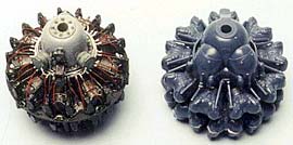
The kit P&W R-2800 had some rather glaring inaccuracies as well as rather misshapen cylinders. The magnetos were of the GE type that were never used on Corsairs. To grind them off and replace them would have been a major undertaking. I put the kit engine together (it took about 10 minutes) purely for comparison sake. I chose to use the now-discontinued Teknics R-2800. It is a superb kit (and judging from the number of pieces that is the correctterm for it) from the word go. The detail is extremely crisp (each cylinder cooling fin is perfect) and it offers all the different types of magnetos and "bullet noses".
I added the ignition ring, wires and push rods as well as some wiring. There is a ring that separates the front and rear row of cylinders. This was not included with the Teknics kit but was a kit part so I used it. The two scale out very closely so fit was near perfect. I had to shorten the back of the engine somewhat so it would protrude correctly in the kit cowling. This was easily accomplished with the Dremel and a cutting bit.

The kit cowling also had several problems with it. The cooling fins were of the wrong number, shape and configuration. They were also horrendously thick scale-wise. I ground them off, replaced them with soda can aluminum and added the actuating pulleys, wires, etc. I also used strip styrene for the internal ribs and stringers. In retrospect I spent way too much time on this cowling but the end result was worth it.
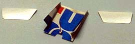
Other engine related scratch built items were the covers for the engine compartment cooling and the oil cooler vents. These were made from soda can aluminum. The engine compartment vent cover was somewhat challenging to make as it had a "pleat" in it. I made it in one piece and folded it along the creases.

Since opening up the cooling vent would then be creating a "black hole" I made a small 'box' out of styrene, with the thought of adding detail later. To completely scratch build the engine mounts, exhaust system and all the wiring just for this one vent was a task that I considered not worth the effort. I used aluminum tube to make the exhaust stubs and punched out styrene discs out for the carburetor blow off vents. Much more detail was added in this area, as a later photo will show. The propeller was basically good, with the proper blade and spinner shape. I needed to add only some minor details to the hub.

The oil cooler inlets at the wing roots were very poorly represented by the kit pieces, so they were discarded and scratch built with a combination of styrene strip, sheet and brass screening. Notice the large strip of styrene at the top of the wing. This was necessary to correct a horrendous gap!

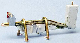
Since I was opening the cowling cooling flaps, the back of the engine would be visible. Before attaching the finished cowling to the aircraft, I mounted the engine on the firewall and scratch built the exhaust headers from 0.100" solder. Most of the work, unfortunately, is concealed under the cowling.
Landing Gear


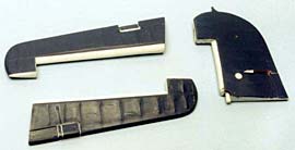
The kit landing gear was in need of total replacement. It was incorrect in size and detail and would have looked very out of place given the level of detail present in the rest of the model. I went to the National Museum of Naval Aviation here in town, took numerous photos and measurements of both the tailwheel and main struts and scratch built them. The kit tailwheel strut depicted the old style (short strut) and the mains were long by about 2 scale inches and extremely lacking in detail. I scratch built the tailwheel strut from styrene the mains from brass, steel, aluminum, wire and styrene. The bracing and actuating cylinders were made from styrene. They are all as close to scale as my eyes and calipers will permit. The tailhook was scratch built from styrene and a chunk of scrap resin and the tailwheel was a piece of 1/2" clear acrylic rod.
Flight Control Surfaces

I cut out the rudder, ailerons, elevators and flaps. In the finished model they will all be in some level of "deflection". Doing this of course means that you must build up the interior surface of the moveable surface, as well as the interior surface of the immovable piece.
I used the Lonestar resin flaps to save a tremendous amount of scratch building time. Bulkheads were also constructed of styrene sheet where appropriate. A word about Corsair flaps. The inverted gull wing of the Corsair is the proverbial "devil in a red dress". A thing of beauty to look at but pure satan underneath. The bulkhead behind the flaps is not flat, instead there is a rounded contour to it. In a wing without a gull wing this would have been easy to do. It took several hours of shaping, grinding and sanding to get the desired look.
The trim tab actuators were made from styrene and wire. Also notice the formation light and fuel filler cap (both not depicted in the kit) on the port wing tip.

The kit provides clear parts for the wing tip navigation lights but they are very poor fitting. I cut a piece of acrylic rod, drilled a hole to simulate the bulb and glued it into place. I used the Dremel, files and sandpaper to shape it and polish it. The wing tip ID lights were made from clear pieces of styrene, painted with Gunze clear colors and punched out with the Waldron punch set. A piece of punched aluminum foil was placed in the hole before the styrene to make the colors stand out.


The flaps on a Corsair are difficult to model. The gull wing, though a thing of beauty, makes for some difficult compound curves. I used Lonestar's outstanding resin flaps. This saved me a tremendous amount of time over having to modify the kit flaps. The bulkhead behind them is curved rather than flat because the flaps were of the Fowler type. Normally this would be easy to do but the gull wing complicates things considerably. I started with a flat bulkhead but added a piece of strip 0.125" x 0.125" styrene strip hollowed out with a circular Dremel bit. Sanding and filling with CA rounded things out. The flaps were attached after painting and hinges needed to be added. There are also spring loaded plates that swing up toward the flaps when they are extended. All of these had to be scratch built out of styrene.
Wheel Wells and Miscellaneous Underside Details

The Lonestar wheel wells were outstanding, as were the doors. I added some plumbing for the hydraulics but little else needed to be done. I used brass rod to make the bridle hooks and aluminum and solder for other details like drain lines and the attachment point for the Brewster bomb rack. Also visible are the details inside the engine cooling vent and the flaps for the oil coolers are in place.
Brewster made bomb racks were in wide scale service during this time so I decided to scratch build one as well. The real thing was rather crude, making the job pretty easy. I had already built the attachment fitting to the underside.
Finishing
The model was primed and painted in the tri-color paint scheme using Testor's Model Master enamels. The kit decals were deteriorated by age and disintegrated as soon as solvent was applied. Fortunately I anticipated this and scanned them at 1200 dpi before beginning construction. I printed them out and made masks for the national insignia from packing tape and hand painted them. It was time consuming but it worked and the results were very good. I used white decal film for the Jolly Rogers insignia and the white "29". The kit "29" decal was too thick so I used the computer to make a new set using the "Amarillo USAF" font available at tlai.com. I also used Archer dry transfers for the stenciling. It was my first time using transfers and it was a bit of a learning experience. Gratefully there was more than one of each.
Weathering
The south pacific was not kind to aircraft. Crushed coral is extremely abrasive and sand blasted the paint from props and leading edges. The reference photos show the outer 1/3 of Kepford's prop almost devoid of paint. The leading edges of the wings had numerous chips in them. I hand painted the chips with Metalizer aluminum. The most difficult part was reproducing the wear on the top of the wings at the wing roots. The rivet heads, even though they were flush, took the brunt of the wear. I nearly went blind painting dots. Radial engines are also notorious oil leakers. I use a combination of Future and brown "The Detailer" (made from red, yellow and black) to simulate oil. I has a sheen to it when dry that looks very realistic. I place a drop on the area and blow on it to spread it out. If you are careful in your alignment, the 'oil' will also follow aerodynamic patterns. When all was said and done, I applied pastels to the upper surfaces to 'fade' the paint and add additional weathering and soot from the exhausts and guns. As a measure to prevent gun jamming, doped paper was placed over the gun ports and shell ejection chutes. I cut pieces from white address labels and covered these areas. The base (not depicted) is covered in crushed coral from the south pacific, Guam specifically. I spent a year there when I was a baby. I did not have any from Bougainville but sometimes you just have to take what you can get.
Scott Murphy has graciously given his permission for us to use this article from his site. Check out Scott's site for some really great models. http://members.tripod.com/scottsmodels/
© Scott Murphy 2001
This article was published on Wednesday, July 20 2011; Last modified on Monday, July 02 2018