
How To Build An FGR in 1/32 Scale - Part 3: The Burner Cans
By Frank Mitchell
I did not really intend to do the third part of my 1/32 FGR project, but a couple of folks asked about it, so thought I would throw it out for general interest. Besides, after doing the first two parts of this dissertation, I unexpectedly developed an incentive to build another FGR, probably because of some leftover decals from the Wild Hare kit.
And, after all, one really does need five built 32nd Phantoms taking up untold space on the shelves...
This is the third set of these exhausts I have built (plus one set of basic moldings sent to a friend). I have added some detail this time around and have made a couple of tweaks to the technique. While I will certainly not be competing with Aires anytime soon, I am pleased with them and think they will "paint-up" to be presentable. I do not claim absolute accuracy, but, given the number of other available burner cans, it was the only way to get them, and I happen to like the airplane enough to do it. Besides, they are kind of fun to do (except for the actuators).
The final disclaimer is that the only specific dimensions I had was for the diameter and the length they protrude beyond the fuselage, both of which checked out quite closely to the RAF Museum's FGR2 (not by me).
The process sounds complicated, but it really isn't. The main hang-up would be getting the basic mold turned and buying a new pair of glasses after those actuators...
Construction
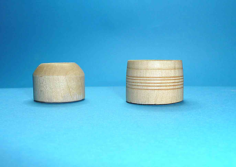
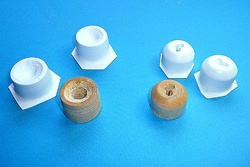
1. The first step is to turn two molds, one for the inner and one for the outer parts. I turned mine from Basswood. The inner mold diameter is 1 3/16 inches wide, and the outer is a "fat" 1 1/4 inches, tapering to 1 3/16 inches. Both are about 7/8 inch high, but that is not a critical dimension. The large holes through the center are to provide more pull when vacuum-forming to make sure the top part forms properly.
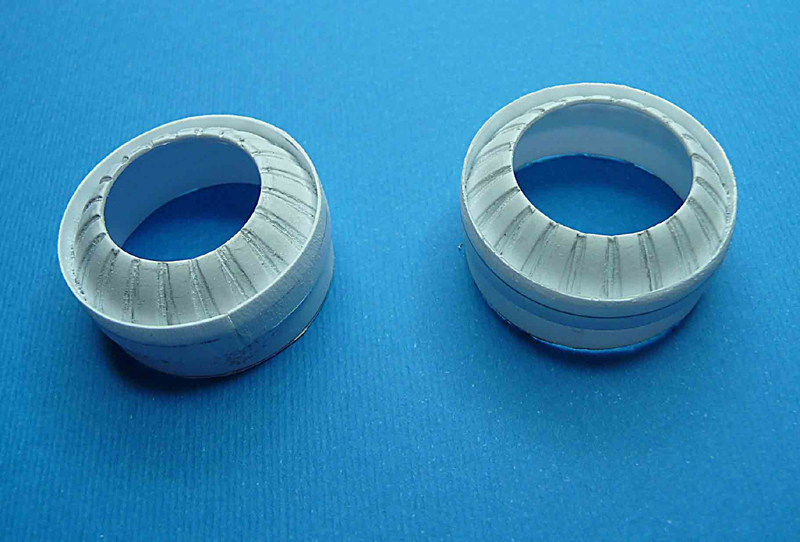
2. While I am a big fan of heat-and-smash, one really does need to vacuum-form these pieces in order to get straight pulls on the cylindrical portions of the molds. Obviously, you need two copies of each. I used .030 styrene, and made sure the plastic was as hot as I could get it without disasters occurring.
3. Most of the work occurs on the inner piece, so the first step was to draw rough lines on the tapered end to represent the divisions between the burner segments. These were about 18 degrees apart (works out to about 3/32"). A line was also drawn for the opening of the exhaust.
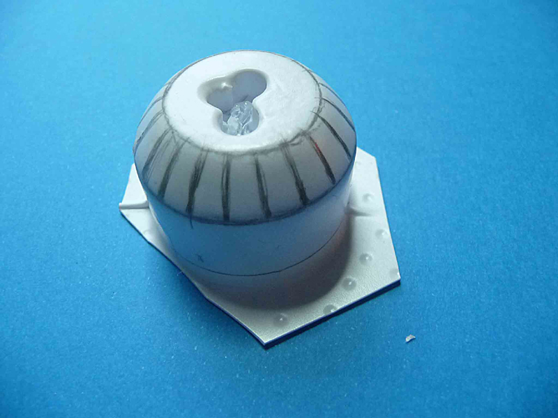
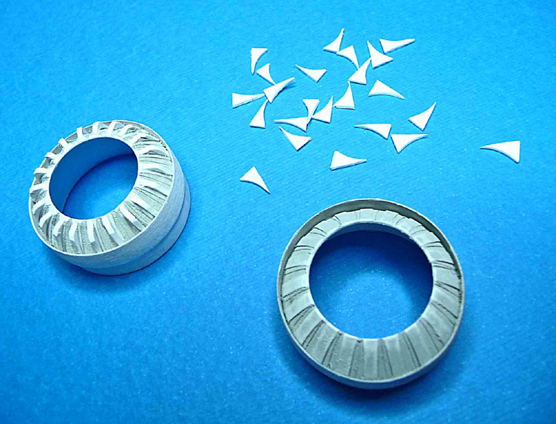
4. The next step was to scribe along the pencil marks so the segments will be a bit more obvious. Then pieces .010 thick x .080 wide styrene strip were added between each line (the middle of each segment) to represent the bottom portion of the actuators.
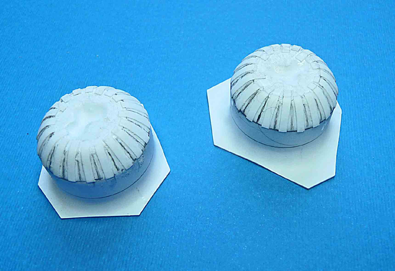
5. After allowing things to thoroughly dry, the main opening of the exhaust was opened up; the "tails" of the strips overlapping the main body were sanded smooth. A strip of .020 styrene about 1/4 inch wide was glued around the upper portion of the can making sure that there was a even overlap of about 1/8 inch. This "shelf" will serve as a base for the actuator arms and will be the main surface to glue the main parts together.
6. Now comes the fun. 40 actuators (20 for each side) were cut from .020 styrene after which each was glued to the center of each strip of styrene on both sides. Sounds miserable, and it is.
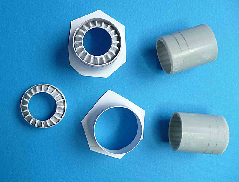
7. Now, at last, the outer piece can be opened up, and, if all went well, the completed inner piece should comfortably fit into the outer with some small degree of adjustment available. The kit exhaust tubes, which are joined as they come from Tamiya, are cut apart and only the center sections are used. A bevel is sanded into one end that will glue snugly inside the actuator part. The other end will need something that looks kind of like the aft part of the engine (or lots of flat black paint). This tube needs to be carefully glued so that the complete burner will fit the fuselage properly, and for that reason, I do not do that until all the fuselage work is complete. Ideally, the burners should end up to be interchangeable between sides and even models.
This is as far as I take the exhausts until the fuselage shaping is complete, The final adjustment of length is also postponed until after the fuselage work is finished.
Final Note: You may notice the line scribed into mold. Fortunately, they did not come through the molding process, for which I am glad, since they are inaccurate. After everything is cut to final size, those rings are added using various metallic shades of paint.
If anyone has questions, please email me.
© Frank Mitchell 2005
This article was published on Wednesday, July 20 2011; Last modified on Saturday, May 14 2016