
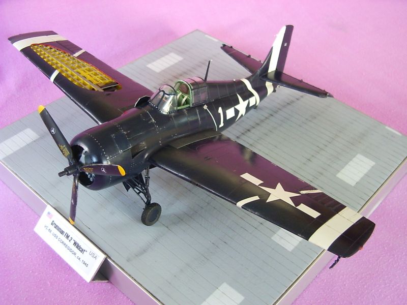
Revell 1/32 Grumman FM-2 "Wildcat" VC 58, USS Corregidor, late 1945
By Chris Novak
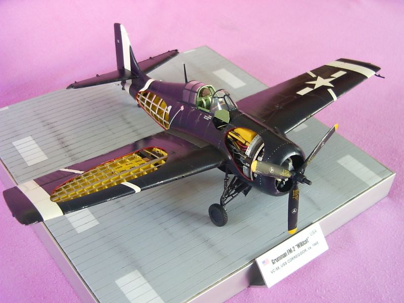
With this article I want to introduce another "blue beauty" from my Navy-collection...Ladies and Gents: WILDCAT FM-2. I was inspired by a original pic of this restored bird and after checking the possibilities to convert a "normal" REVELL Wildcat F4 into an FM-2 I decided to start the work to get a not often seen Wildcat variant. The major modifications/ differences between this two variants are: modified/ larger vertical stab , modified cowling because of the power-plant – the FM-2 was fitted with a Wright CYCLONE - and modified prop. Also the "normal" work while building an old REVELL kit had to be done which means re-scribing, sanding, filling and scratching...uhhhhhhh...I love it! ;-)
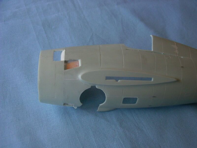
This time I started the project with the major modifications of the fuselage halves because I was waiting for a resin Wright CYCLONE I had ordered at Great Models. Unfortunately the order was canceled a few weeks (!) later because it was out of stock, so there was no other chance than to "scratch" the CYCLONE from a modified spare P&W which finally turned out into a nice looking motor. Here are the modifications of the fuselage:
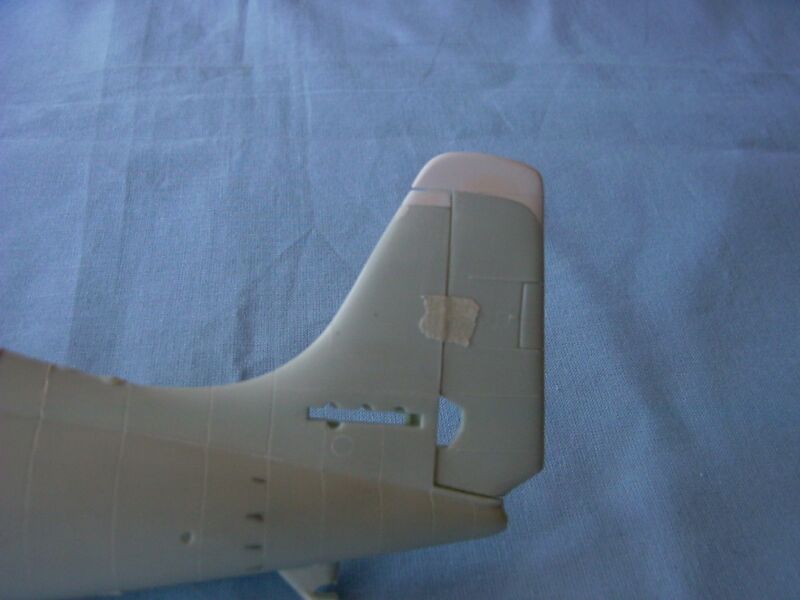
Cowling shape / flaps/ exhaust openings modified and vertical stabilizer modified by inserting sheets of styrene.
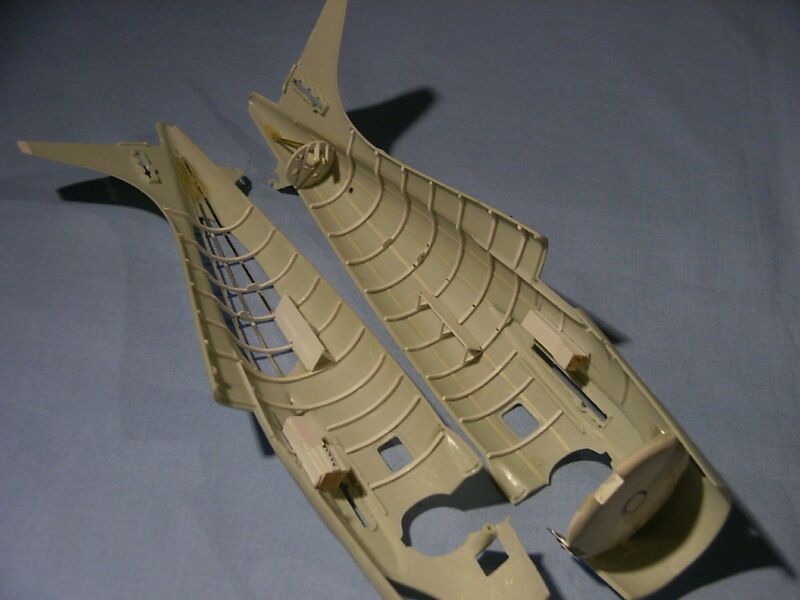
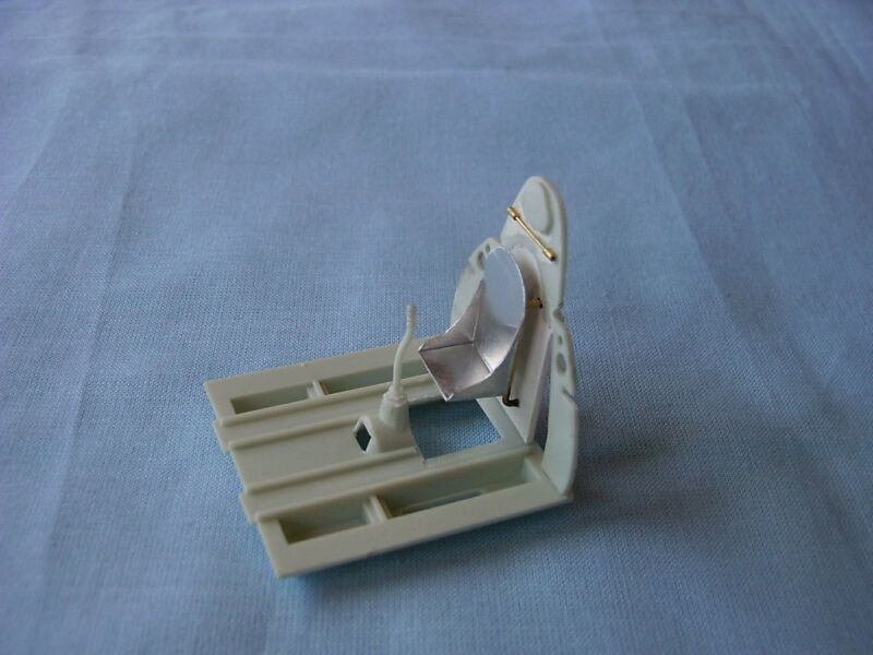
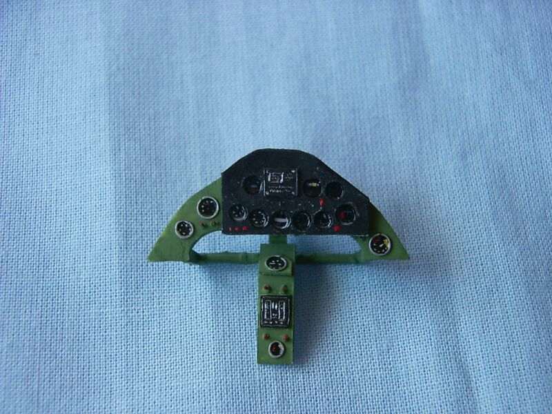
Work continued as usual with building the inner structure of the fuselage, inserting cockpit ( again completely scratched because of the bad REVELL cockpit) and adding first details into the motor area (building a cutaway always is a bit like building a "ship in a bottle": you have to work from "inside" to "outside").
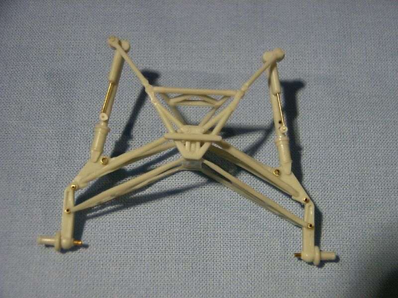
The landing gear was used OOB (compliment to REVELL, a nice replica of the original mechanism!) and modified by adding a few metal parts.
As usual both fuselage halves were painted and filled with details and interior like radios and rudder-wiring before they were glued together.
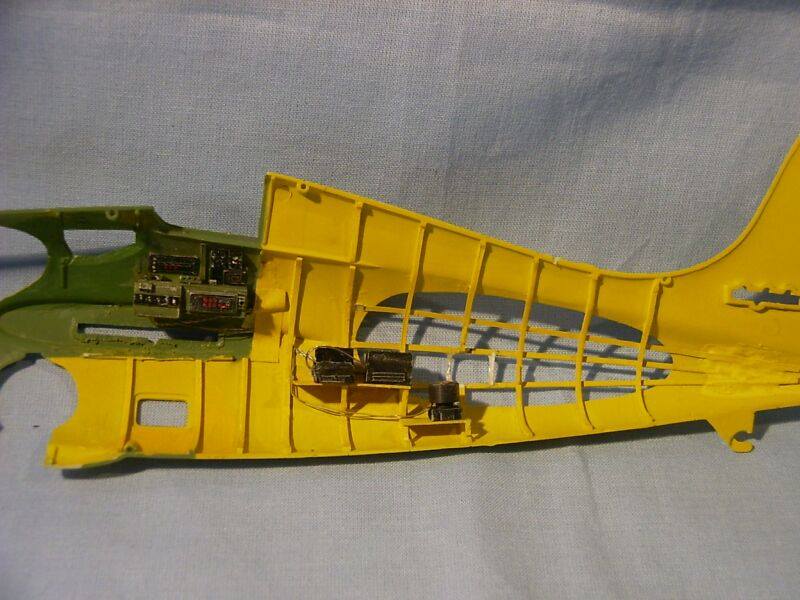
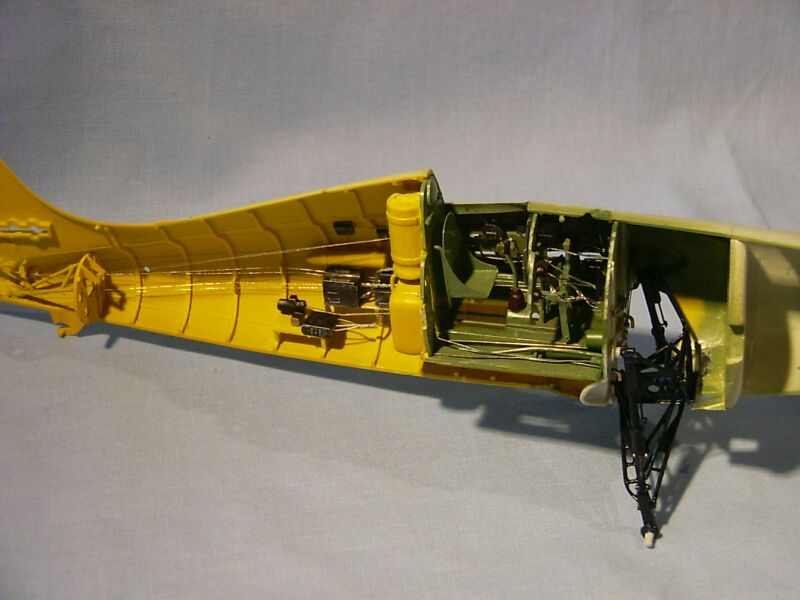
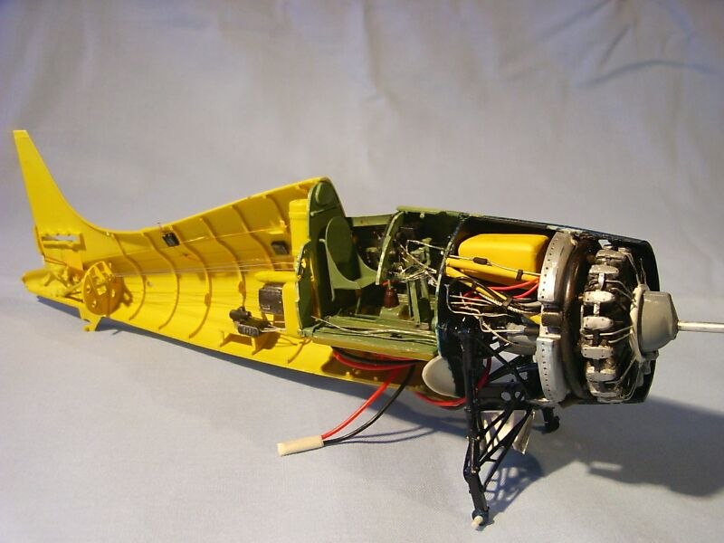
Also the scratched Wright CYCLONE has to be installed before mating the fuselage halves and, not to forget, the small electrical main-board for the working position lights was installed, this time it was placed under the cockpit floor. Power connection to the board as usual comes trough tiny electrical wires, "camouflaged" as break lines and going through the landing gear to small contacts into the base where the power pack / batteries ( 2 x 1,5 V) is installed.
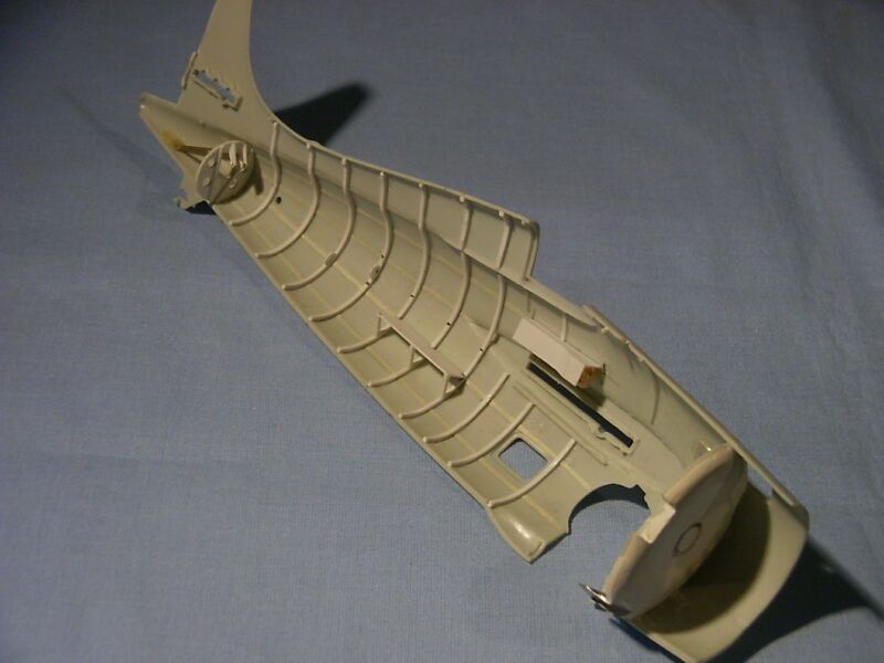
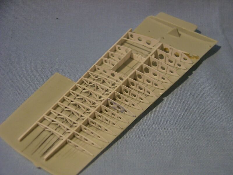
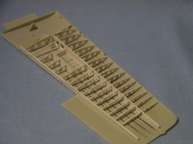
After the fuselage was done work continued with starting the starboard/cutaway wing, as usual done from styrene. Here you can see clearly the difference in a wings construction – for example compared to a Hellcat wing - I mentioned before in part 2.
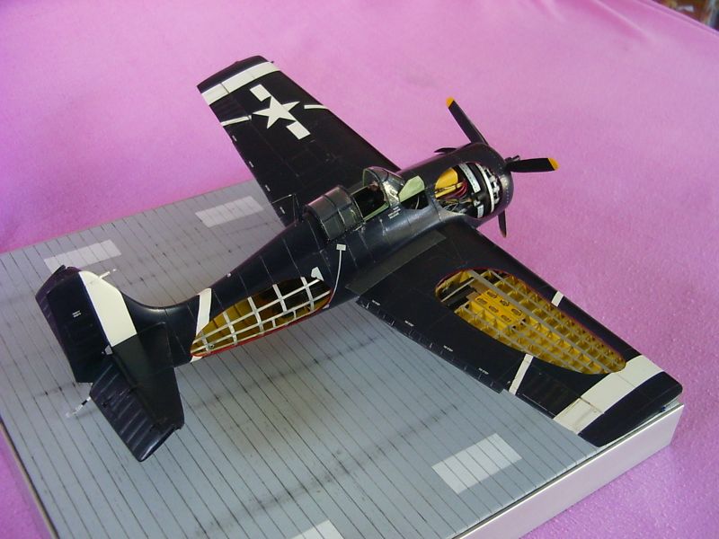
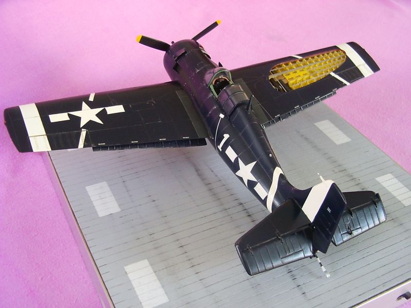
From here on the built continued the normal way with an overall blue paint job, doing the white markings and giving her a carrier base.
Thanks again to all LSP mates who helped with some references!
Enjoy, Chris "the ripper" Novak
© Chris Novak 2007
This article was published on Wednesday, July 20 2011; Last modified on Saturday, May 14 2016