
Packing and Shipping Models
By Brian Leitch
After modeling many different scales of aircraft as a kid, and as many others have done, taking a hiatus from the hobby, I have gotten back into aircraft modeling after many years, and I have found a new love of modeling; LSPs.
After building my first few LSPs of my 2nd "modeling renaissance" then moving on to find my stride and making a few that I felt could be entered in contests, as well as accepting some commission builds, I found out some things. Not the least of which was where the hell do I put them?
The second thing I found myself asking was "how do I transport them?" Whether it be to and from an IPMS meeting or show, or across the country shipping to a customer.
This article will cover the 2nd of the two...transporting your LSP safely, weather that be to a local IPMS show, or taped up nice and secure to ship across country to for a customer build; this method can be used for either, depending on weather you use the 2nd external box.
In the method I am showing here, the internal structure of the box containing the model does not need any tape, glue or anything else to hold itself in place, other than its own structure. It requires only reusable dowel pins to hold the model itself in place inside the structure. This method is also re-usable to take to shows and meetings, collapsible so you can either break down the containing box, or throw it away, then stack the structure neatly for storage. I am use standard UPS, USPS, FEDEX sized boxes; in this example, 18" x 14" US. There is nothing too fancy here, and different items can be subbed in for things I have used, IE different types of foam cushioning or slim bubble tape wrap for the green house construction style cushioning I have used here.
So here we go...
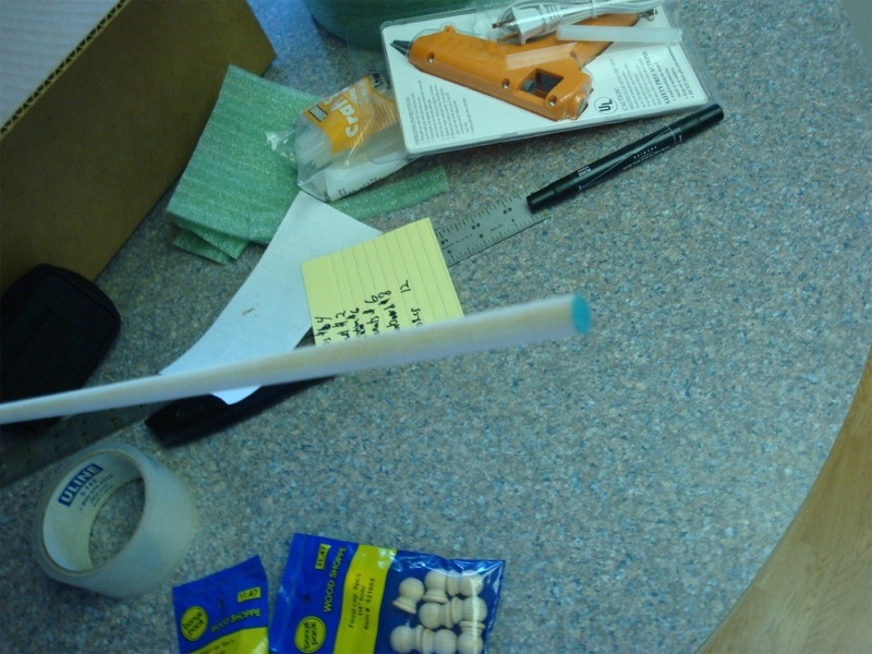
Things you will need:
- 1 box that is at least 1/2" to 2 1/2 inches clearance all the way around the model and deep enough to center the model height wise, and have 3-5" clearance top and bottom both (or a bit more)
- 1 box at least 2" larger than the previous box in all dimensions (If you are NOT shipping via USPS/UPS/FedEx/Other, there is no need for this step)
- 1 roll of 1/4" (approx) thick of cushioning or very fine bubble type wrap
- 1 20" x 30" sheet of 1/2" thick foam board (if your LSP is REALLY "L" then you may need to pic up a second sheet of 20 x 30 foam board)
- Straight edge
- 1 marker (Preferably) 2 sided with fat and skinny tips
- Razor saw
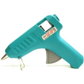
- Low temp hot glue gun
- 1 extra pack of low temp hot glue sticks
- Dremel tool with cutting disks (could sub in another cutting device here if needed)
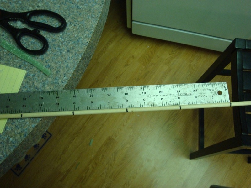
- 1 36 x 1/4" or preferably 48" hard wood dowel rod
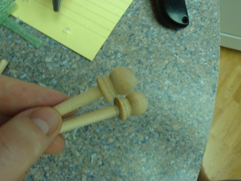
- 2 packages of corresponding size wood press fit caps
- 1 large roll Packing tape
- 1-2 large bags of Foam peanuts (if shipping in mail system)
You can start by taking measurements of your LSP.
In this case I am using my P-51D Dixie Boy as an example so I can take her to the local IPMS meeting. In my case, Dixie Boy is approximately 14 1/2 x 12 1/2 x 4 1/2 inches high (from the top of the rudder to ground when wings are perpendicular to the ground). You will want to use the size of standard box that best fits your model with at min of 1 1/2 inches to 2 1/2 inches clearance all the way around it.
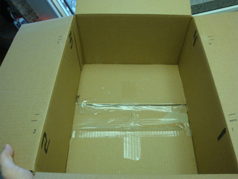
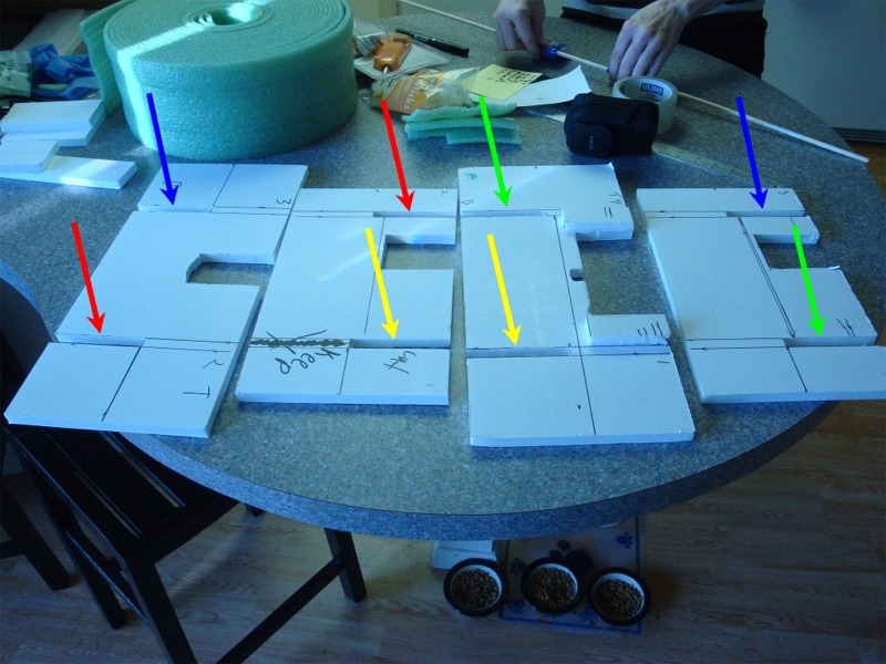
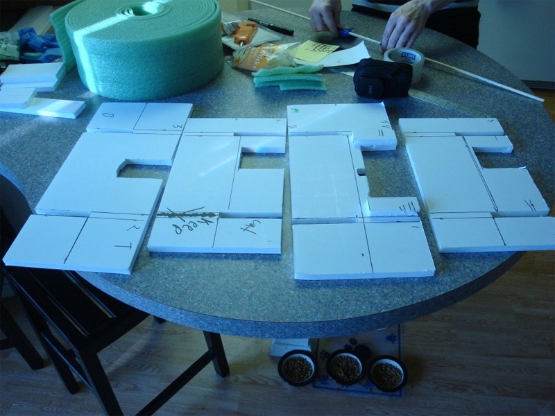
In Dixie Boys case, this calls for a standard 14" x 18" box. I got this one from the UPS store. I have marked the corners in sequential numbers. This will line up with the internal support structure of the box and make it easier to put back together or take down after the model is back on the shelf.
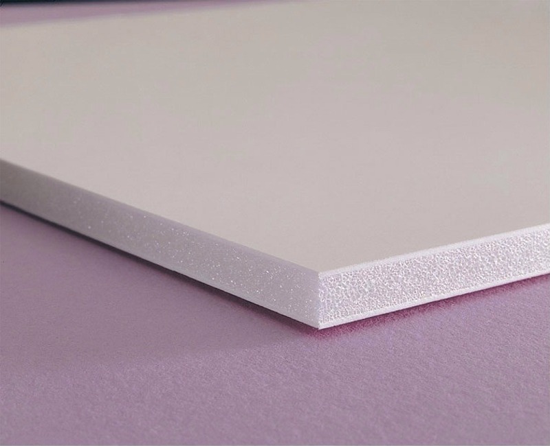
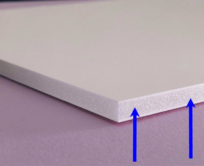
I am using a sheet of 1/2" thick artist´s foam-board, Foam Board - White 20"x30" for the internal structure of the box.
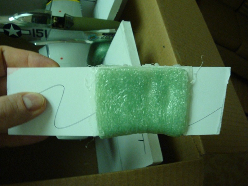
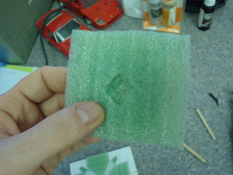
You will also need some sort of cushioning for the cross structure, in this case, I´m using an air-filled strip cushioning that I believe is normally used in US housing construction, but any good 1/4" cushioning would work.
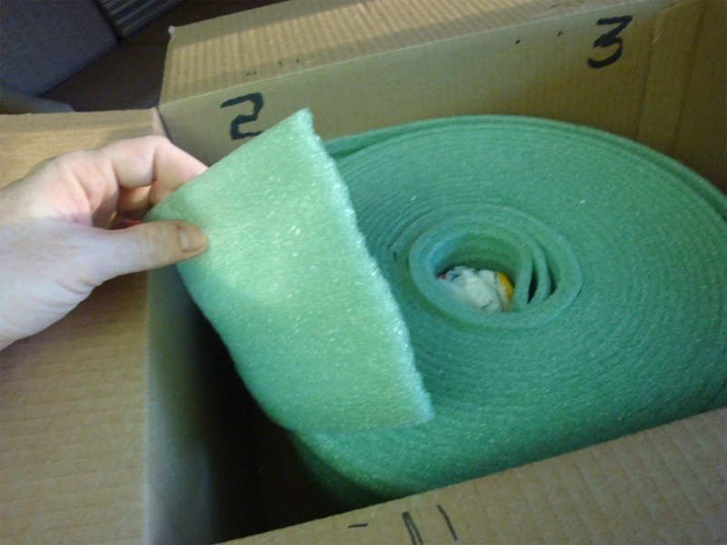
This cushioning will need to be thin like this, and have the ability to lie around corners. You will also need to be able to cut it in strips.
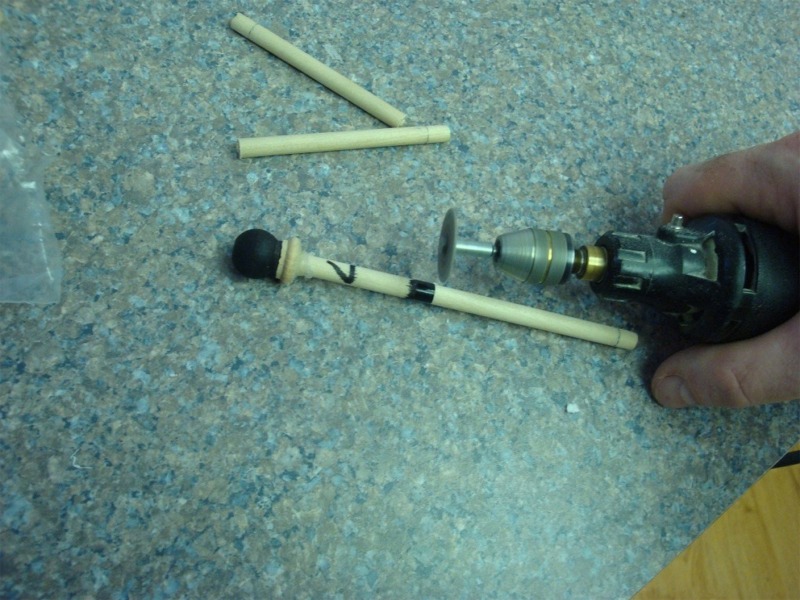
Next you will need one standard 1/4 inch hardwood dowel rod (usually these come in 36" or 48" lengths. I suggest getting the longest dowel you can), and some corresponding sized wooden caps. Both the rod and caps are usually sold at craft/hobby shops, as well as some hardware stores. I picked mine up from the local "Hobby Lobby"
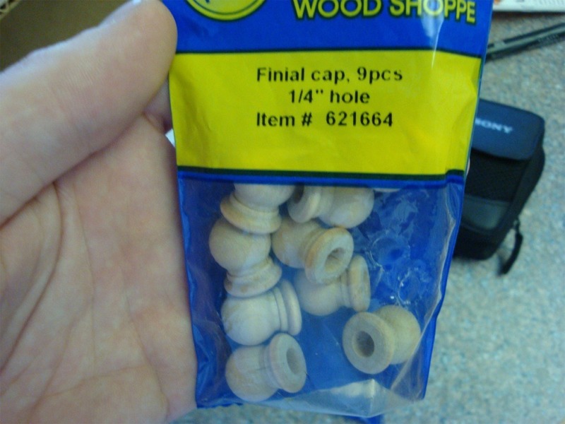
There are many types of wood caps available. They don´t have to look exactly like mine; they just have to be the correct size for the dowel rod you have used.
These are press fit, and the harder you "press" the tighter they fit. These do work well and stay put quite well too. For the marking and numbering you will need a marker (preferably one with a wide and narrow tip on it) and a hot glue gun for attaching the foam cushioning. I chose hot glue for this method, as the foam cushioning does not have to bare any weight, and the foam cushioning I used in this case was quite unbelievably resistant to both CA and epoxy. The hot glue is the low temp type hot glue gun, and gives a permanent bond to the cushioning, and is again available at most hobby/craft stores as well as a few hardware stores.
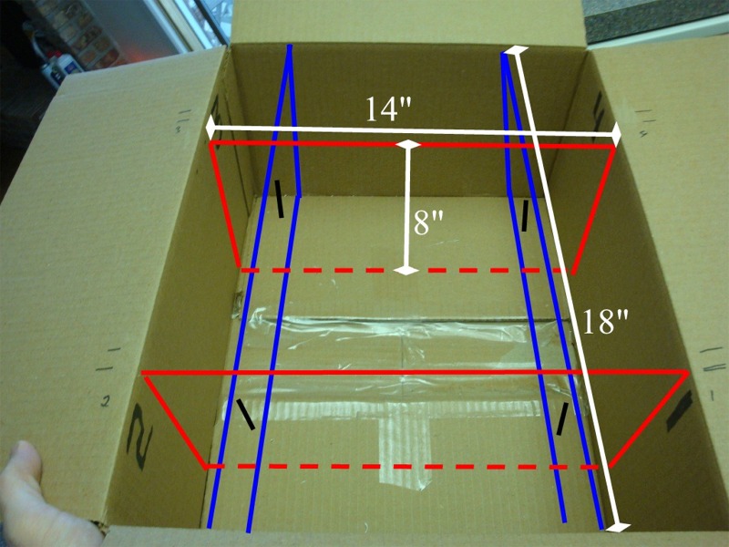
The secret to this method is that it´s self supporting. So carefully, measure the length, width, and height of your box, and cut out your pieces appropriately.
You will want two pieces of foam board length wise, and two width wise in the box, each exactly as high as the main part of the box itself. In this example I will need two boards 14" x 8" (RED) and two boards 18" x 8" (BLUE)
After cutting your 4 boards out, you can take your next measurements.
Set the two longer sized boards in the box, and you can gauge about how far apart each of the 4 boards should be relative to the box; IE you should try to center (as much as you can) the four boards left to right, and front to back, so they support the model evenly. Again this could change for different shaped planes, such as twins, bomber, twin tails or the like.
Use the marker to measure and mark the top of the foam pieces where the other boards will intersect, again keeping it as even as you think it should be...things can be adjusted later prior to the 1/2" slats being cut.
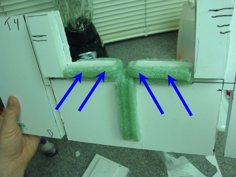
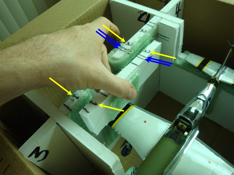
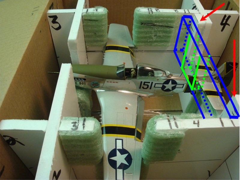
Since the 1/2" slats that allow both boards to intersect are not cut at this point, the mark will be on the top edge (Blue arrows) of the board at the point where the two boards intersect (shown with yellow arrows).
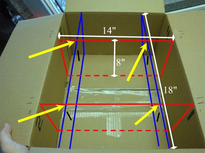
These marks can also be adjusted later prior to cutting as needed.
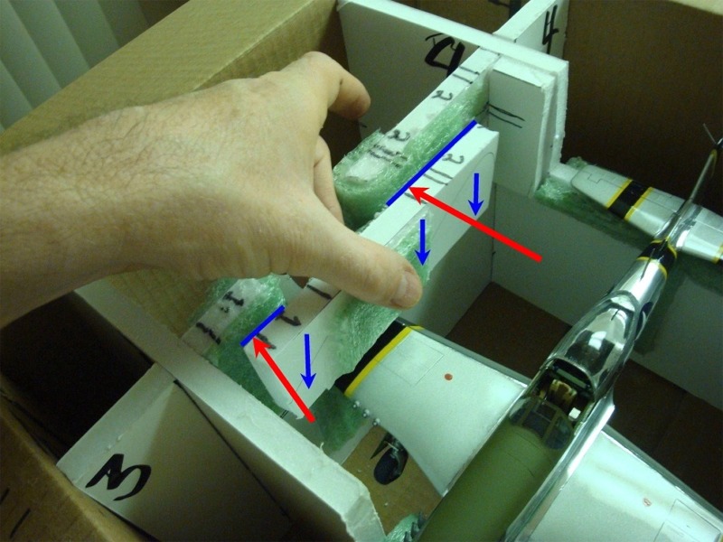
It is as this stage with the two longest boards setting in the box perpendicular to each other spaced apart as evenly as you can, you will want to physically pick your model up and make sure that you can hold it over the measurements you just took, and none of the 2 walls will(remove longest boards and repeat procedure with two shorter boards to make sure wings are supported in the same manor described) interfere with the model making sure it gets supported by both wings and the tail, and the boards contact the model in places that will not knock off or interfere with the model during transport. Make sure you account for, and give room to, things like flaps, landing gear, pitot tubes and the like.
ALSO be very aware of where the best places for the model to be supported are at; in the rear of the fuse, front bottom of the fuse (if possible), and the wings especially.
The best places to support Dixie Boy are under the fuse behind the tail wheel, and under the chin of the cowl. I am not putting anything over the top of the nose, as the Moskit exhausts are too delicate for this; so its supported here on the bottom only.
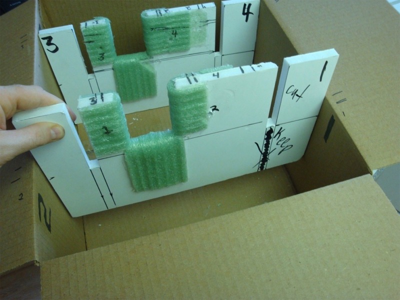
Once you have these dimensions worked out and are comfortable with no pieces of the model being obstructed (you can also cut sections out of the structure that interfere, as I have here for Dixie Boys elevators in blue and fuse cutout in red) you can proceed. You will want to cut any openings that will come in contact with the model to be a bit larger than you think they may need to be, as these areas are going to get wrapped in the foam cushioning.
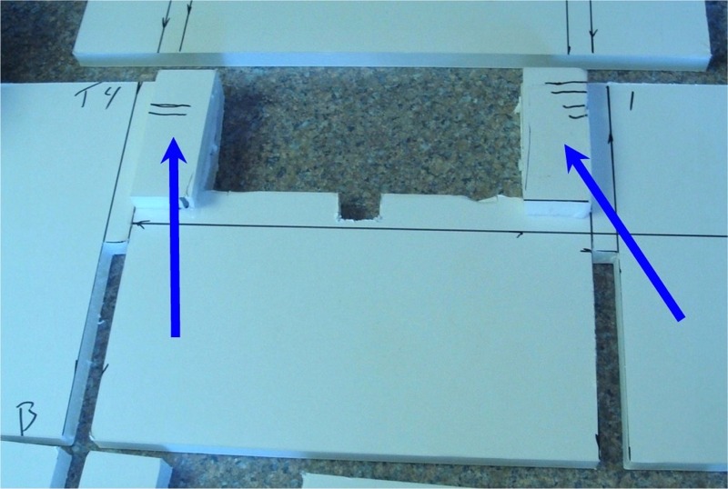
Measure in from the outside walls of the box along one of the wall inserts (as seen in the white dimension arrows) to get accurate Idea of where to cut the 1/2 inch slots that will run 1/2 the way up (top to bottom) each opposing internal structure so the boards intersect like a cross.
Here is one of the width wise panels and its cutouts:
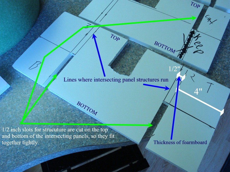
Again, CAREFULLY measure from the end of your boards, taking into account the 1/2 thickness of the board itself and cut your 1/2 "slots using the razor saw. In this case its 4" from the box edge to the start of the 1/2" slat, then add 1/2" beyond for the thickness of the foam board, again, as seen in the white dimension arrows in the previous pic.
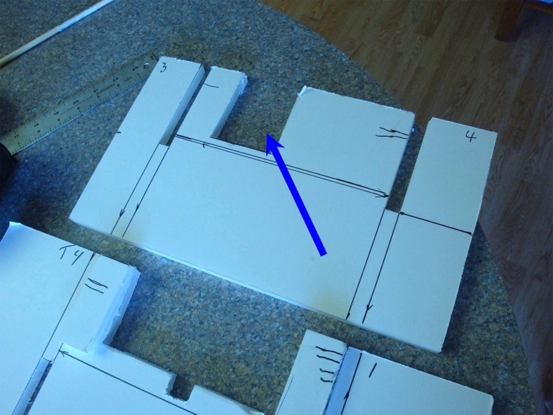
The 4 boards once cut, will intersect each other via the 1/2" slots and form their own self supporting structure. MAKE SURE YOU CUT THE 1/2" SLATS ON OPPOSITE SIDES TOP AND BOTTOM SO THEY CAN FIT TOGETHER LIKE A CROSS.
You can see here, looking at the color coordinated arrows how the slats should be cut to fit. (Picture the boards assembled in their final form and you can put the like colored arrows together and get a better idea.)
Test fit, test fit, test fit!
Once you have the boards fitted together in the box as you would like make sure you number each corresponding board/corner with the number on the box you marked earlier.
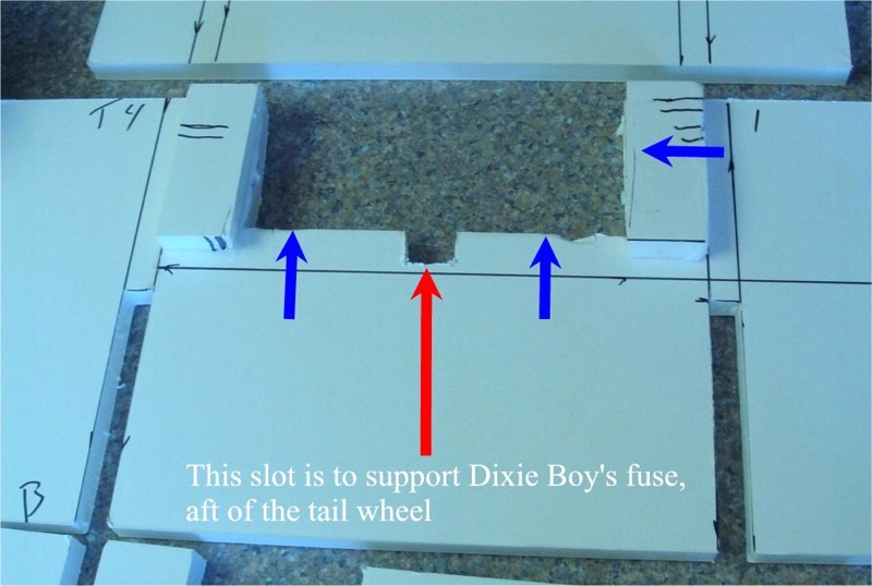
Once the board stats are cut, you can assemble them in the box, & you can do as I did and let the model sit on top of the 4 intersecting boards, and use a marker to mark then cut out where you need to get it supported by the wings and rear fuse and nose. For the nose in Dixie Boy´s case I have support only under the nose and no top bracket will be fitted.
MAKE SURE YOU CUT THE AREAS THAT SUPPORT THE FUSE AND WINGS TO THE SAME DEPTH OR YOUR MODEL WILL NOT SIT LEVEL IN THE BOX!
You can see the cutout made for the elevators and rear fuse. Here you can also see the two small rectangular pieces I glued on to the rear panel, that brings the rear brace forward so it rests on top of Dixie Boy in a place that will not interfere with the antenna or any other structure -
Here you can see the cutout for the starboard wing. Port wing cut out is the same.
You should end up with 4 boards, cut to intersect each other, and then cut out to fit the particular plane you want to transport.
After test fitting the actual model for space (you don´t have to actually put the model in its new confines, you can just hover/rest it over at this point to check you have all openings wide enough.
Make sure cut the openings at least 1/4-1/2 inch larger than your model, to account for the thickness of the foam wrapping to keep things from getting marred up.
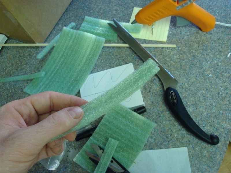
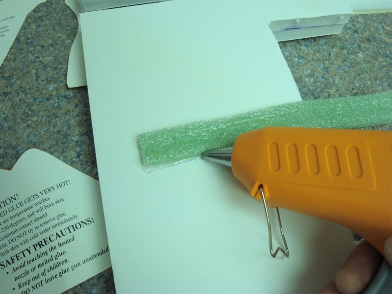
Once the model has more than enough clearance (a bit more room here is probably better than too little) you can use the straight edge to measure then start trimming pieces to cover any edges that will come in contact with the model.
Then use your hot glue gun to attach the strips to cover the edges where the model may contact. Cut the strips longer than may be needed, so you can pull them taught (but NOT stretched tight) around the places that will be contacting your model. This will also give you a good surface area to let the hot glue secure the foam cushioning.
Here at the rear, I have cut and glued a couple additional smaller strips as the fit for the rear fuse was not initially as snug as I would have liked.
Front nose section
Continue this way with the hot glue and foam cushioning until you have covered all of the areas of the foam-board that will come into contact with the model.
Continually fit, and re-fit to make sure none of the model bits hanging down are touching the foam-board. Once you have hot glued on all of your covering you can re-assemble things and make sure the foam cushioning doesn´t interfere with the structures assembly. Cut off or remove/reduce any foam that doesn´t allow the structure to be re-assembled correctly.
Using the numbers you applied to the boards earlier, and corresponding box sides, you can assemble things easily the way they came out. Be sure to label all corners on all 4 boards with their corresponding box corner number!
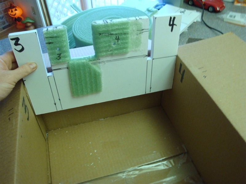
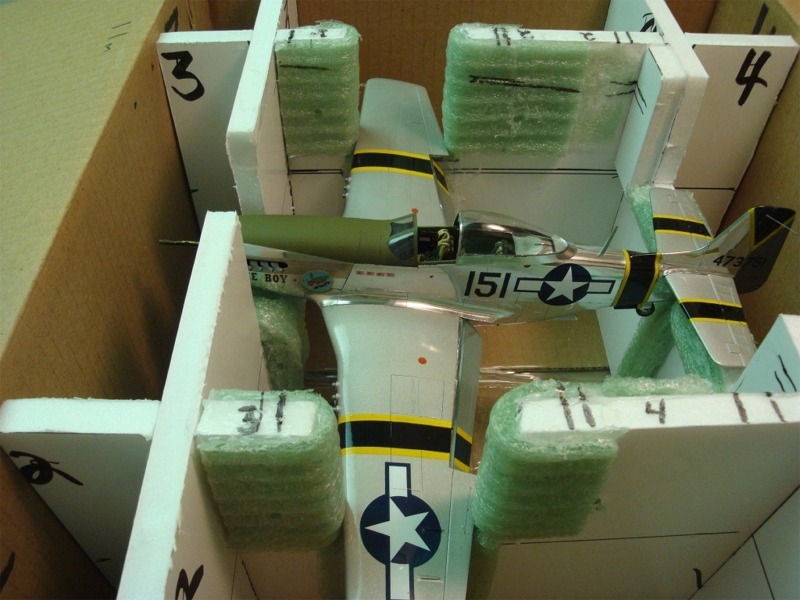
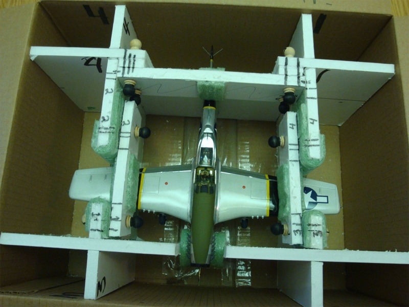
You should end up with something that looks like this
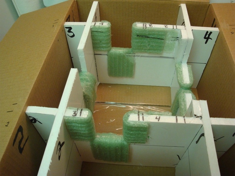
Here is DB resting comfortably in her new transport digs...although NOT fully secured yet be any means.
The next step is to take some of the left over foam board and cut 2 pieces, 2 inches longer (or more) than the gaps cut in the panels to hold the wings. You can measure the gap that you cut where the wings will rest, and cover this extra strip with the same cushioning.
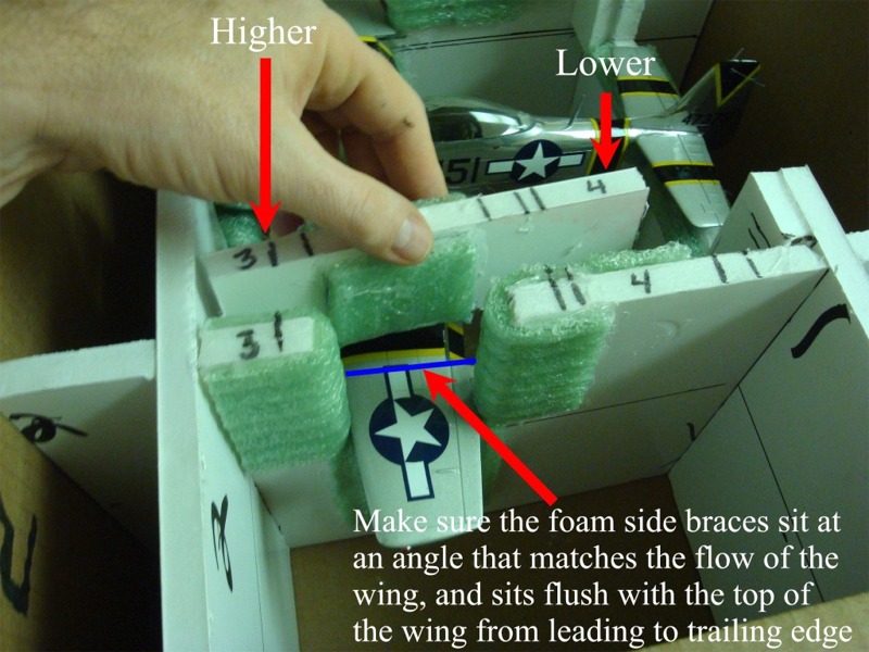
Here I have notched out an airflow shaped section and covered this section that will touch the wing in the same green foam. These side panels should be 2-3 inches longer than the gap cut for the wings on each side, so the dowel pegs will have plenty of material around them.
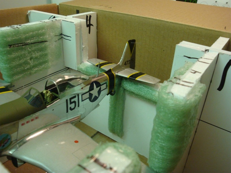
Make two of these, 1 each for the port and starboard wings. Once you have chopped them to length, and added the foam cushioning, you can hold them up to the inside of the structure (with model in place) over the wings.
Make sure you maintain the angle of the wings; you can see here how these pieces go, with the side on the trailing edge of the wing lower than the side where the leading edge of the wing resides, to match the angle.
You can see I have also numbered each of the wing pieces as well as marked them with a striping code, for ease of re-assembly, and to make sure everything fits together later.
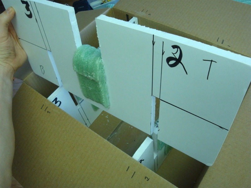
Now we need to make the rear cross brace.
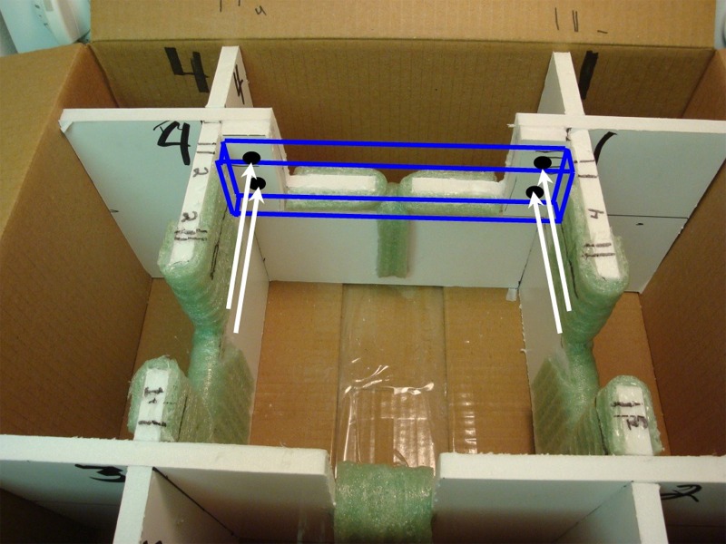
Using more of the left over bits of foam board take and measure the inside distance between the side boards that are supporting the wings, and make a piece that is flush with the top, fits snug between the side boards and is deep enough top to bottom to put 4 holes in for the dowel rods. Holes here are represented by the black dots.
With the model safely sitting in the structure, set the rear cross brace on and test for fit. The bottom of the rear cross brace should barely contact the model, with the top of the brace, sitting flush/even with the top of the rest of the boards. You may need to cut some off here, or cut a notch in the bottom of the brace to accept the shape of the rear fuse where the brace contacts it. AGAIN KEEP IN MIND THIS AREA WILL ALSO NEED TO BE COVERED IN 1/4" FOAM CUSHIONING AS WELL SO LEAVE A BIT OF EXTRA ROOM HERE.
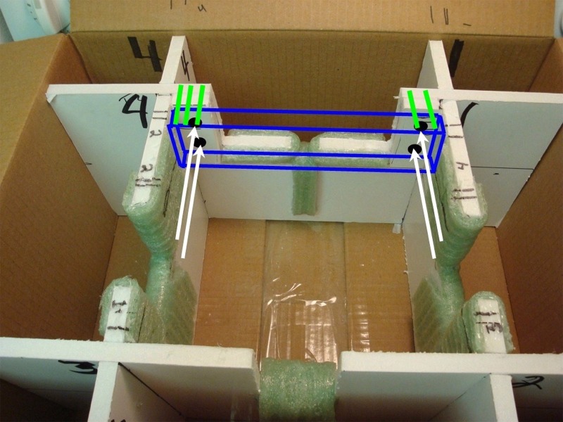
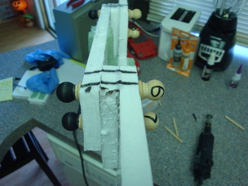
Once the rear cross brace is in snugly in the position you would like it in, take and mark some identifying marks on each side, so you can tell which side is which, and which side goes up.
I have done this by putting 3 lines across all the layers on one side and 2 on the other. I did this with the thin side of the marker, but here is represented with the green lines.
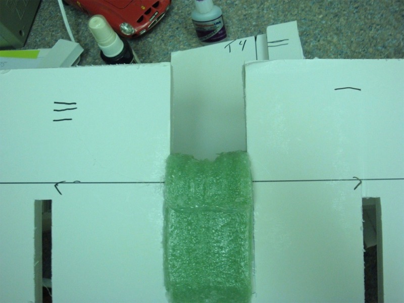
After measuring and cutting your rear cross brace, set your model in the cradle temporarily and determine what section of the rear brace comes in contact with the model and make sure it doesn´t interfere with anything on the top of it. The area represented by the green box here will need to be wrapped in the foam cushioning where it comes in contact with the model.
ONCE AGAIN -BEFORE hot gluing the foam cushioning on the rear brace, make sure the brace is just barely IF AT ALL touching the model, and cut away some of the rear brace if necessary so you maintain the correct pressure/contact with the model after the foam cushioning is on. You want a nice snug fit but not too much pressure on the model.
I´m my case, I added the two earlier mentioned rectangular pieces (red arrows) to bring the rear cross brace a bit forward so it does interfere with the rudder fillet or the antenna.
Next up is securing the model.
Take your dowel rod and measure the distance needed to go all the way across the layers of foam board PLUS AT LEAST 1/2" EXTRA JUST IN CASE. In my case this was less than 3", so I marked and cut my dowel rod into 3 inch sections; as many as a standard 36" or 48" rod would produce. MAKE SURE you leave at least a 1/4" or more for the caps to grab hold of the ends of the dowel rod. Test fit a cap on the rod to see how far down the cap comes on the rod when twisted on very tight, and you can get any idea of how long the rods will need to be cut.
AGAIN, you can ALWAYS cut more away, but you can´t add, so too much here is WAY better than too little when it comes to cutting the rod. I have used a Dremel tool here to cut these, but you an use the razor saw as well, it will just take a bit longer.
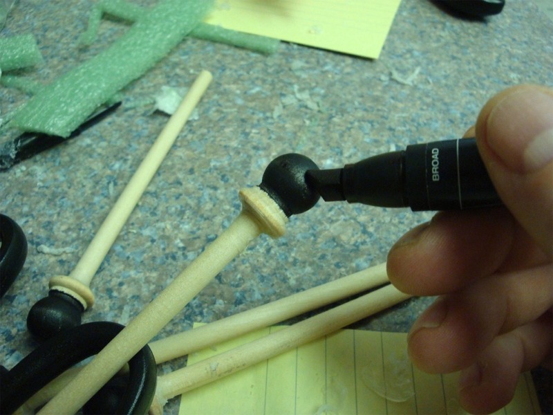
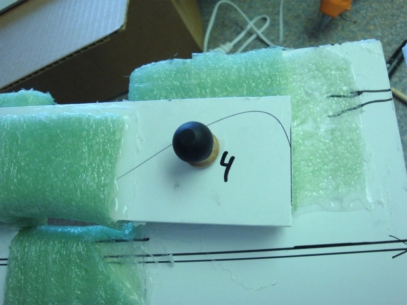
After you have cut your dowel sections into the individual lengths needed to go through the two layers of foam board (or in the rear brace´s case 3 layers) PLUS a bit extra, take your wooden caps and hot glue on a wooden cap on only ONE end of each of the dowel sections you just cut. Press fit this one cap on tightly so the glue oozes out. CAREFUL HERE AS GLUE IS LOW TEMP BUT STILL WILL BURN IF YOU TOUCH IT TOO SOON! If you wait a bit (but not too long or it will dry hard) you can wipe off the excess glue around the joint. In my case, I am using two dowel rods for each side of each wing, and 4 for the back, for a total of 8.
I found it useful to know which end was which, as you will have 8 rods, each with one side glued, and one side press fit.
I took the fat end of my marker and colored the end I am gluing on permanently, so I´m not continually trying to twist that end off. At this point, all the dowel rods are cut longer than they need to be, and will be cut down after final fitting.
With the model setting in its foam crib, take one of the pieces of foam board you just created to hold the wings in place, set it in place, and gently push down just a bit on that piece, so you get the level of pressure you want to hold the wing in place and mark a line on the structure wall where the wing brace piece should set (solid blue lines), as well as marking lines back and front so the padded area of the brace sets directly on top of the wing, again, making sure the brace matches the wings angle from leading to trailing edge. Repeat this step for the other wing.
Next, gently remove the model and set it aside. Then, disassemble the structure. Take the side walls you just marked and lay on the wing/side brace, lining it up with the marks you just made, and mark holes roughly in the middle of the pieces on each side of the wing cutout, to accept the 1/4" dowel rod pieces. With the structure still disassembled, and the wing brace piece you marked up earlier, lined up with the marks, drill 1/4" or slightly smaller holes all the way through the wing brace and structure wall. (the example pic here is with the structure assembled for clarity sake ONLY. Make sure you have the model out and the structure disassembled prior to drilling the holes for the dowel pins.)
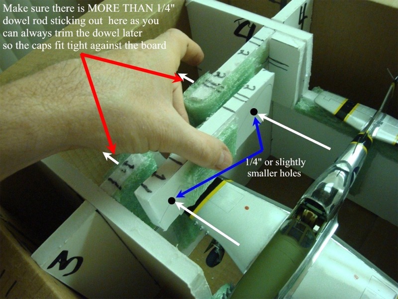
The dowel rods, with caps should go all the way through, and there should be enough dowel rod sticking out the other side to press fit the other wooden cap on. AGAIN, too much is better than too little here. You can cut or sand them down later so the caps fit tight against the board and keep everything snug. Make sure to push the glued cap end of the rod all the way in till its flush snug against the board and then put on the press fit end.
Repeat this step for the opposite wing.
With the structure still disassembled, take the rear cross brace you make earlier and line it up with the 5 marks (2 on one side and 3 on the other) you made on both sides, across the brace on to the back board. Drill out the 4 rear holes in the pattern shown represented by the black dots. Again make sure you leave AT LEAST 1/4" or more sticking out for the cap to secure to.
With all 8 of your holes drilled, lined up and in the position you want them, measure the dowel rods and cut them off so that a touch more than 1/4" is sticking out beyond the end of the outer most section. DRY FIT THIS AND MEASURE FIRST! DO NOT cut them off too short! You can always take more off if they are too loose!
Measure 4 or 5 times...cut once.
Just make sure to test fit the press fit end of the caps to see how much dowel you will need sticking out, to ensure the caps stay on firmly, and are snugly up against both sides of the board without crushing.
I used a dremel tool and some tape to measure and cut the dowels, but you could use the razor saw for this as well.
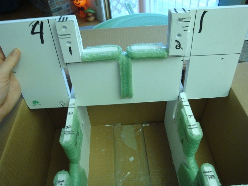
You should end up with them as close as you can to the end of the "sandwich" without crushing the foam board. AGAIN, measure VERY carefully here to ensure you have enough dowel sticking out to secure the dowels to the caps firmly You can see the completed foam board "sandwich" here as well as two of the back brace alignment marks. The base of the caps should seat snugly against the board like this without crushing it.
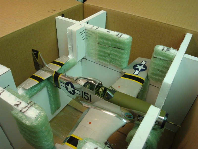
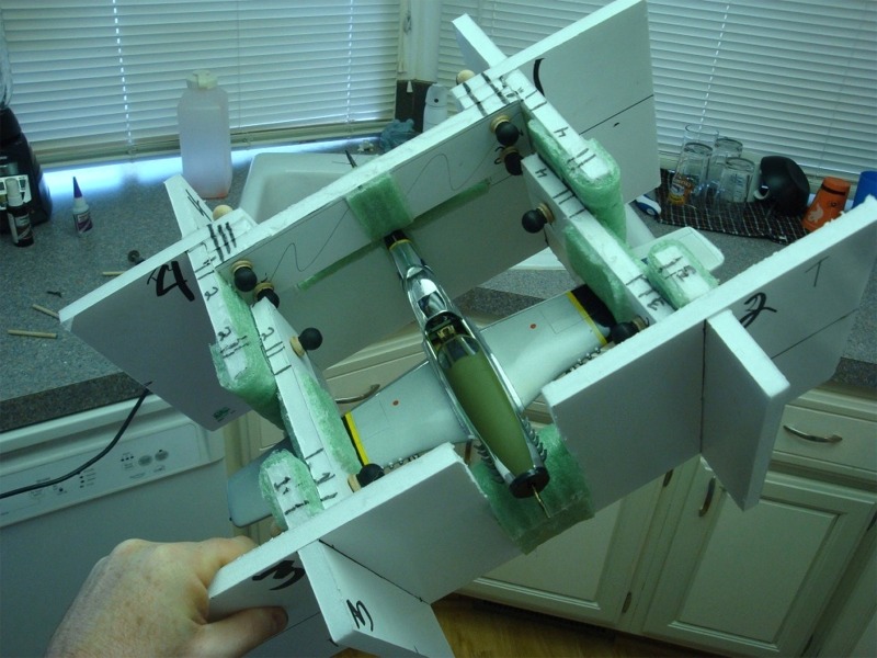
Once you have measured, cut and fitted your dowel rods you are ready to test fit your model! You should end up with something that looks like this:
Once securely locked in, and all of the wooden caps securely press fit/twisted on, the structure completely supports itself, even out of the box, without touching any of the gear, flaps antenna or other delicate parts of the model.
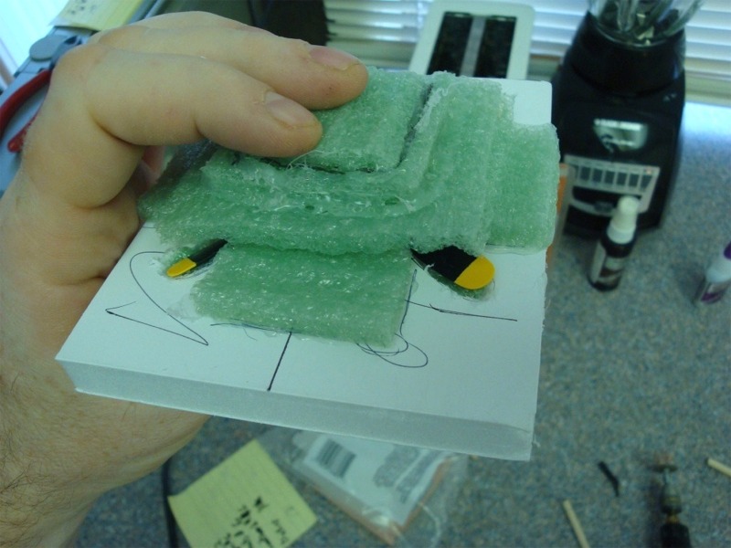
Next up (in the case of prop jobs) is a small holder for the prop. Here I am using a small scrap of foam board slightly larger than the prop itself, and traced the outlines of the prop onto the foam board, and cut out around the spinner and prop blades.
I have cut sections of the green cushion foam and added them in between the blades so all of the blades are supported. I used more green cushion foam at the tips of the blades as well.
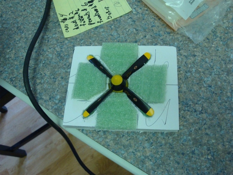
I then took several squares of the green cushion foam in consecutively smaller pieces, and cut small holes in each (also consecutively small as you go up) and glued them together so it fits over the top of the spinner.
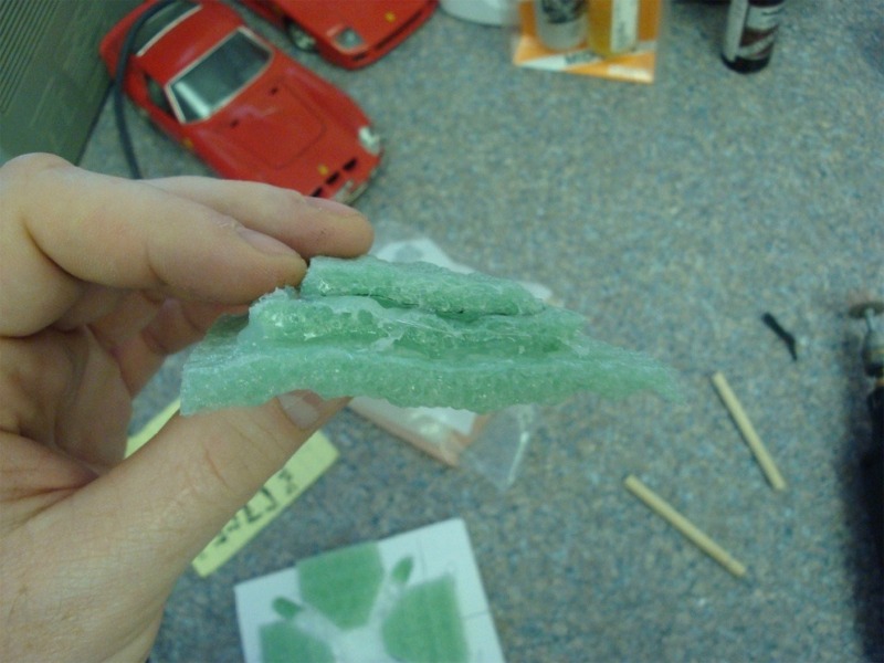
Once glued together, you can seat the stack of foam cushion over the prop and then cover the whole thing with a larger sheet of the foam cushioning and secure with tape or rubber bands for transport inside one of the suitably sized pockets created by the foam board when in the box.
There you have it!!
Sound, snug, secure, and best of all, re-usable, collapsible, and in the end, will only cost you a bit of time, and most likely 20-25 USD in materials.
Scary as it is, once the structure is together, with dowels in place, and caps press fit, the structure completely supports itself , and is capable of easily being handled (even with delicate model locked in) with or without the box itself.
The previously described method will protect your model to and from any local meeting show or event. If you wish to ship your model in the shipping/mailing system then you will want to make sure all your caps are on tightly (the press-fit of the dowel/cap combo is powerful enough to stand shipping), then tape the box up securely.
Now get a standard box that will allow for 2" or slightly more space all the way around top AND bottom of the box you just made the structure for.
Take the larger box and layer in 3" of foam peanuts on the bottom of the box. Place your LSP box containing the model on top of that.
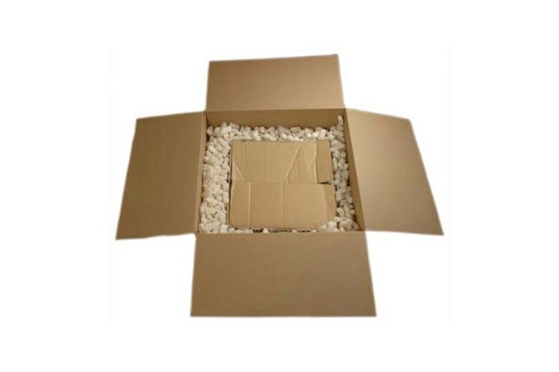
Now simply fill in the rest of the sides around the interior box with peanuts, then fill the remaining space on the top with peanuts. Make sure to over fill the top just a bit so the inner box does not bounce or move in the larger box at all and stays in place.
Tape all gaps and openings around the outer box securely, and mark with "Fragile" and "this end up" tags.
Pray.
Happy (and safe) modeling!
© Brian Leitch
This article was published on Wednesday, July 20 2011; Last modified on Saturday, May 14 2016