
Echelon 1/32 BAC Lightning F6
By Michael Ibbotson
The Real Aircraft
It is hard to believe that the concept for the Lightning arose in 1947. Just two years after WW2, designers were putting together plans for an aircraft that would fly in excess of Mach 2, attain climb rates of 50,000 feet per minute and climb to 40,000 feet in 2 minutes 30 seconds. The English Electric/BAC Lightning is a superstar amongst post-war aircraft: when it first entered RAF service as the F1 in 1960 it was nothing less than miraculous. To add to its potency, pilots had to have 1000 hours in Hunters before flying it, so the RAF had the world's supreme fighter, flown by experienced pilots.
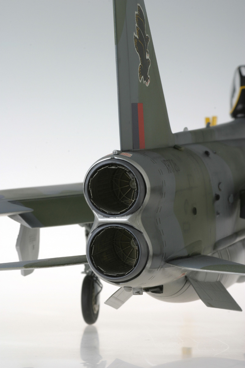
The Lightning used several engines throughout its career, culminating with the twin Avon 301Rs, which each produced 16,300 lbs static thrust in an airframe weighing just 28,000 lbs (empty). Even when loaded with fuel and weapons the Lightning hovered around a power to weight ratio of one, which goes a long way to explaining its amazing performance. The wing design was unique, with the speed advantages of a highly swept delta but with greatly improved turning performance because of triangular notches cut away close to the fuselage. These notches reduced the drag when the wing was exposed to oncoming airflow during tight turns. A very unusual feature involved stacking the engines vertically, instead of the now familiar side-by-side arrangement. This is certainly unusual but good design because if one engine cuts-out there is no lateral instability, which has led to many F-14 mishaps.
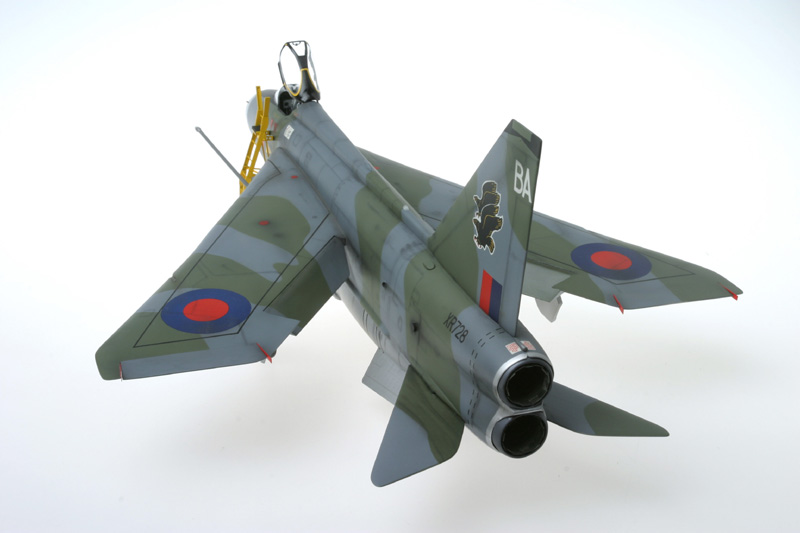
The basic design never changed but improvements and new models came along regularly. The first improvement of note came with the F2, with new engines and a revised cockpit but the F3 brought the major advances, with the ultimate 301R engines and a square-cut tail. The F3 was then redesigned with a double-cranked leading edge to the wings (designated F3A), thus further improving manoeuvring capability. The T4 and T5 were twin seat versions and they were followed by the final new-build RAF Lightning, the F6, which was to all effects an F3A with more fuel. To complete the story, 31 F2s were converted to a standard close to the F6 (designated F2As). The distinctive feature that immediately identifies the F2A and F6 is that they have two ventral strakes instead of the single strake carried by all other versions.
Building the Model
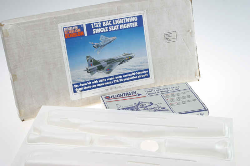
The Echelon vacform kit of the Lightning F2A/F6 was designed by Frank Brown and became available in the early 1990s. In recent times it is probably only available by searching on the internet, as I did. I bought mine second hand from the USA after the former owner realised he wouldn't ever make it. The shape and surface details of the plastic are exceptionally accurate. The kit also comes with a clear canopy, a bag of white metal parts, plastic rods, a huge decal set and very clear instructions. I also splurged and bought the Flightpath update set for the kit, which contains a pair of Firestreak and Redtop resin missiles plus several extensive sheets of etched nickel-silver parts for the missiles, missile trolleys and many aircraft components. The latter include a fold-together cockpit tub, jet pipe details, ventral strakes and FOD guards. The update set also provides new main wheels.
I started the build by getting all the cutting out done in one go. I cut around all the plastic components with a Stanley knife at a 45 degree angle at the join line. This done I placed wet and dry sand paper onto a table top and, using plenty of water, started to sand the joining surfaces flat. While this is a distasteful job, after surprisingly little time I had everything I wanted sanded flat and from then the construction was not dissimilar to a normal injection moulded kit. It is at this early stage that you need to decide if you want the wheels down. I went for this option and consequently cut out the wheel areas from the lower wing surfaces. One last preparation job requires you to remove all the surface dimples, which are a side effect of the vac forming process. I sliced each off with a sharp scalpel and lightly sanded the entire surface.
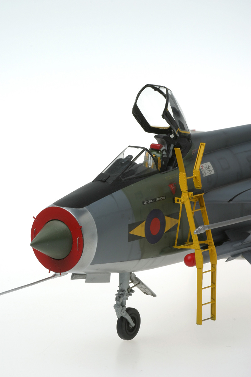
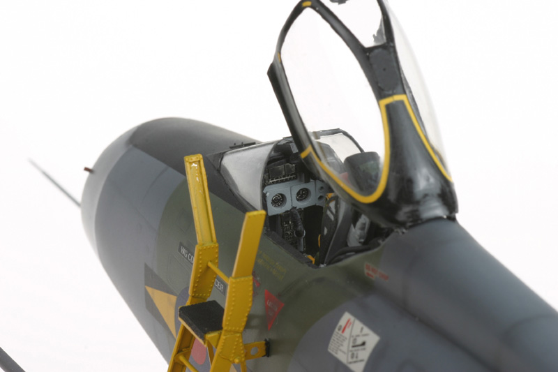
I chose to use the plastic cockpit tub from the original kit because gluing it internally was far easier than the metal tub from Flightpath. However, I did glue the metal sheets onto the plastic to provide wonderful texture to the cockpit walls. The white metal seat that comes in the kit is a joy to behold and with the Flightpath additions builds into something quite special. I built and painted this early in the piece as a relief from sanding!
The next job was to construct the aircraft innards. The air intake is a complex affair that includes the front wheel well but, despite its complexity everything fit perfectly. I should note here that one difference between this kit and an injection moulded model was that I used thin strips of white plastic to reinforce all the seams, always gluing the strips to the non-viewed side of the seam. The only weak parts of the kit are the after burner cans. When the two halves of each can are glued together they formed oval shapes that are virtually impossible to correct. Instead I went down to the local plumbing supplier and bought a metre of 20 mm plastic plumber's pipe. This is exactly the correct width, so I cut the appropriate lengths for two burner cans and sanded the nozzle ends into appropriately curved shapes to match references. I then inserted the internal details from Flightpath and sprayed the insides silver.
I glued thin white plastic around the entire edge of one half of the fuselage such that about 3mm of plastic would overlap with the other fuselage half. This provided the essential bonding surface when the two halves were joined. While I let that glue dry overnight I inserted all the internal frames that hold the fuselage shape, including the air intakes and front wheel-well. The next day was the big moment! With everything glued into one half of the fuselage I placed plastic glue on all bonding surfaces and joined them. After applying tape in liberal amounts to hold the joints together, I left it for two full days to cure. On removing the tape I had a fuselage strong enough to throw at the wall. I chose not to use the metal nose ring from Flightpath, but instead used the original plastic one from Echelon painted with Humbrol 11 paint. It didn't matter what I did to the Flightpath offering I could never smooth it sufficiently to fit on the model. It looks great in the box but not on the model.
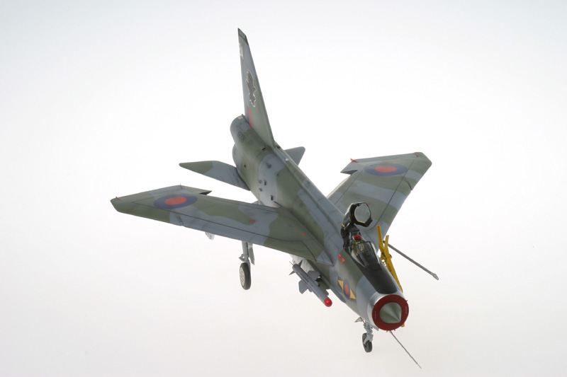
Next, the main wings and elevators were constructed. The elevators are very simple but the main wings are not. First, when cutting and sanding out the main wings you have to build-in the double camber on the leading edges if you build the F6 version. This was not easy but the guide to the method is very clear and easy to follow. I was very careful to sand both sides of every wing edge very thin so that when joined the leading and trailing edges were appropriately narrow. At this point in construction I visited the north of England and went to Teesside airport, which was Middleton St George air base during the Lightning era. On display is a beautiful F3 with its flaps down. I took loads of photographs and decided that the flaps on my model needed to be lowered. I did this by cutting out the flaps from the wings, then bonding the parts together with a plastic pipe between them at the joint where they would meet the wing. I could then place the flaps in the wing and rotate them up and down, just like the real thing.
The inside of the lower wing has the wheel well and wing box glued into it. Before doing this I inserted all the internal bits and pieces provided by Flighpath. The surface detail these parts offer is truly worth the effort. When it comes time to bond the wing surfaces together you must remember to place glue on the upper surface of the wing-box/wheel-well structure and to place weight onto the wing top. I used superglue for this purpose because I didn't want the plastic glue to melt the upper wing surface. If you don't do this step the wing will gape at its centre and looks terrible. I also glued some plastic strip between the outer wing halves and used clamps to hold those gently together, also to prevent gaping. Once the wing was together I placed the flaps into the gap at the trailing edge and lowered them to their maximum position. Once constructed, the main wings slot into recesses on the fuselage walls. I expected many problems with this stage but when I slotted the wings into place they fit perfectly with no adjustment required. The kit is so well manufactured that they just fit.
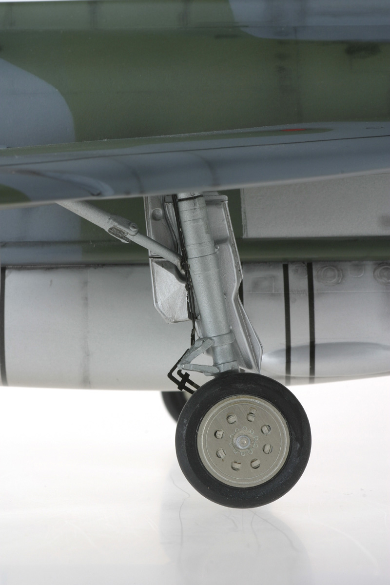
I assembled all the undercarriage components with relative ease after sanding off rough mould seams from the white metal. I sprayed everything with enamel steel coloured paint. The tyres were painted black then the Flightpath wheel hubs were glued into place without painting. The silver-nickel looks marvellous. Before connecting the undercarriage I went around the model adding the hundreds of little bits and pieces. These included the missile rails, the tail hook and many drainage or gas outlet vents. I had to be creative to make these. The rounded vents were made from the tips of sidewinder missiles from a 1/32 Mirage kit, the rounded exhaust pipes were made by cutting plastic tubing at 45 degree angles and the other shapes were cut from white plastic sheeting.
The best parts from the Flightpath set are the ventral strakes, which look far better than ones made from plastic sheet. I had some troubles cleaning up the join line but when done they truly lift the model. Another wonderful series of parts from the update set is the detail provided for the inside of the undercarriage doors. The doors are a major feature of the Lightning when sitting on the ground and the very thin silver-nickel components with rivets look really superb.
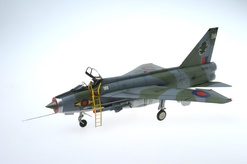
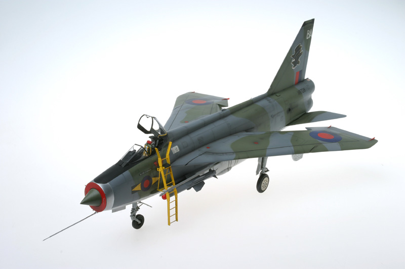
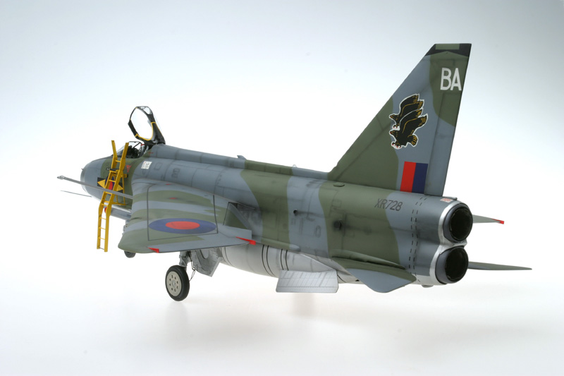
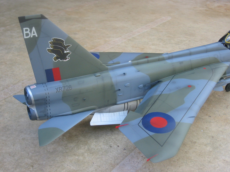
With construction complete, it was time for paint. I had quickly decided to go for an F6 because the F2A requires some extra construction and I simply couldn't face any more! Long before buying the kit I knew I wanted a camouflaged bird, so No 11 squadron it was. The scheme is extra dark sea grey and dark green upper surfaces and metallic lower surfaces. I used SNJ to spray the lower surfaces. After the first few coats you see every single scratch, but this gives you the opportunity to gently sand them all away with very fine wet and dry. Once done I sprayed again and sorted out any final scratches. Then a final coat gives you a perfect finish. The upper surfaces (and wrap-around under the wing leading edges) were sprayed grey using acrylic paint and final scratch marks sanded out. Another coat of grey gave a perfect surface. I then masked the complex camouflage shapes and sprayed with acrylic dark green, being careful to point away from the mask edges. I then masked the metal lower surfaces and sprayed Tamiya clear onto the upper surfaces. Decal application was tricky. The walkways were a nightmare and I would certainly spray these if I did it again. The main decals went on quite well and responded to decal solutions. I mixed some white glue with water and applied it under most decals to make sure the decals were secure. Decals were placed directly on the silver under-surfaces without need for clear coats. Once completed, I sprayed a last clear coat on the upper surfaces and then sprayed several flat coats over the entire model. In places I added either a drop of black or brown to the dull coat to blend things together and start the weathering process. Weathering was completed by spraying dark grey in places and by using pastels. I did not outline the panel lines, as is so popular, because the subtle lines that Frank Brown built into the kit look absolutely in-scale after general weathering.
Flightpath provide a beautiful step ladder, which I included on my model, primarily because it is such a wonderful kit in itself! The ladders were painted several colours throughout the Lightning's service life. While strictly not correct for an F6 from the 1980s, I chose to paint mine yellow to add colour to the model. I also added the red Flightpath FOD cover to the nose of the aircraft, again to add colour. To be strictly accurate I should have also added FOD covers on the exhaust nozzles but I wanted to show their internal features. I also finished by adding some aileron wedges at the rear of the wings, as appear in many photographs of the real thing. The Flightpath kit comes with two resin missile alternatives, and in-keeping with the 80s theme, I used the redtop missiles. These need the resin fin areas thinning to match the etched metal fins, but basically build-up very well with little filler. Other features in the update set that I really liked were the fold-up canon ports, which really add an air of authenticity to the model.
This model is truly beautiful but if I ever do another large Lightning it will be the Trumpeter kit! I had never built a vac-form model before but this one fits better than many injection moulded kits I have dealt with. While construction was lengthy, the process was a joy. When people look in my model cabinet, most are automatically drawn to the Lightning. I highly recommend the project to anybody that likes a challenge.
© Michael Ibbotson
This article was published on Wednesday, July 20 2011; Last modified on Saturday, May 14 2016