
Scratch-Built 1/32 Breguet 941S
By Emmanuel Gato
A Crazy Idea
I have had the idea of building a scale model of the Bréguet 941S (please note the "S" for "STOL", as the 941 was different) for more than 20 years. I could find the starting date of my preliminary work thanks to a drawing dated from 1993, drawn with drafting pens on top of it!
For many years, I have only been scratchbuilding my models. It gives me a total freedom to follow my imagination and whims, without waiting for the – perfectly legitimate – market studies of the kit manufacturers.
But this approach comes with many constraints: need to have an extensive documentation, and a necessarily long time for designing and then building the model, especially in 1/32, my favorite scale.
On top of it, a model is only the visible part of the iceberg in my view. In parallel to the model of the aircraft I am building, I want to know as much as possible about the original: its design, its performance, its systems. It is therefore above all a technical approach.
I hesitated for a long time to tackle the Breguet, in spite of all my friends who had been encouraging me for years: I thought it was too complex, and that this model was far above my modelling skills.
Nevertheless, I took the plunge one day, and, even worse, I decided to build the model in the same scale (1/32) as the prototypes I had completed before, like the Mirage 4000, the Mirage G8 or the Mirage Balzac. As each time (but only after everything is done) I find myself saying that, had I known the adventure to which I had committed, I probably would never have started it in the first place. The Breguet 941S does not contradict this thinking, and it took me 2 years and more than 2500 hours to complete it, and then that is without counting the time searching for references and information, and drafting the drawings. I must be crazy, am I not?
The Aircraft
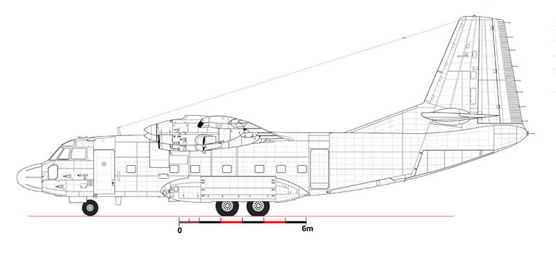
Because of the lack of specific documents, I had to draft my own drawings. I did this always keeping the future model in mind, i.e. representing on the drawings all the details that would be on the model later.
I started from a manufacturer blueprint in 1/20 (an original profile dating back from 1963) with a number of stations and dimensions indicated, which made my work easier in the end.
In the '90s, I could approach the real aircraft in the reserves of the Musee de l'Air in Paris (where it is still today). I had taken a lot of measurements, and, having been allowed to climb aboard, I had also taken a lot of pics of the inside, thinking that they could be useful one day. What a great idea this was!
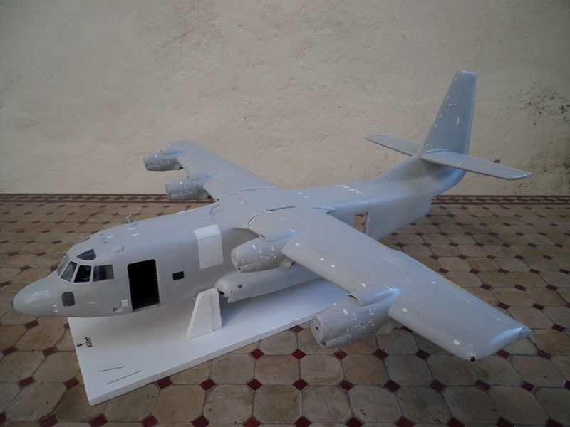
The CAD drawing was thus an exercise trying to match the original drawings with my measurements and pics. I have to say I was gobsmacked when I completed the first drawing and got it printed: the original aircraft is in real life "reasonably small", but, in 1/32, it was going to be some 80cm long, and of equal span. I had never built anything as big as this one.
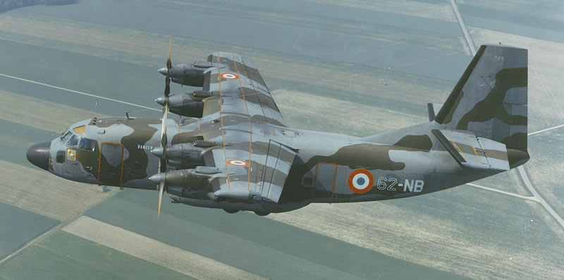
I chose this aircraft because it was technically interesting, and I had seen it fly when I was a teenager. I had kept a memory of an astonishing aircraft, and all the Armée de l'Air staff that approached it just told me the same.
The engineers at Breguet took a gamble, and the (commercial) result was not met, with only 4 aircraft built.
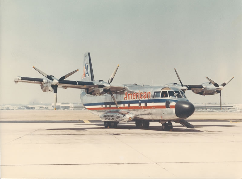
It even flew in the US where it bore the name McDonnell-Douglas 188 in 1968. It was a trials campaign organised by the FAA, Eastern Airlines and American Airlines. The idea was to attempt flights between airports and city-centers, with 50 passengers on board, taking off just in front of the boarding gates of the terminal buildings!
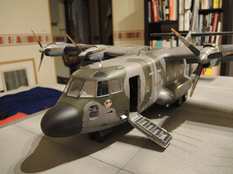
The principal feature of the Br 941S were its amazing take-off (in 200m!) and landing (in 150m!) performance. I therefore wanted to show it with its flaps down, as it owed its incredible performance to them [and to the concept of blowing the whole area of the wing and flaps – translator's note].
20 years ago, I thought it was a fabulous aircraft. Nowadays, with some additional aeronautical knowledge, I have a better understanding of its (half) failure:
- A short fuselage with a high vertical fin made it sensitive to traverse winds
- The main landing gear track was narrow, and its shock absorbers fairly soft (its external props did hit the ground sometimes)
- The unpressurised cabin implied fairly low altitude flights with passengers
- Whereas the turbines that powered it were more efficient in altitude
- The inter-connection gearing of the 4 props (to keep the STOL performance even with an engine out) was an ingenious system, but it implied a great complexity and induced high maintenance costs.
These factors explain the lack of sales success. But those who believed in it and built it deserve our consideration. I wanted with my modest means to pay a tribute to these ingenious designers, who (still) enjoyed the right to be imaginative and forget about economics.
The Nose
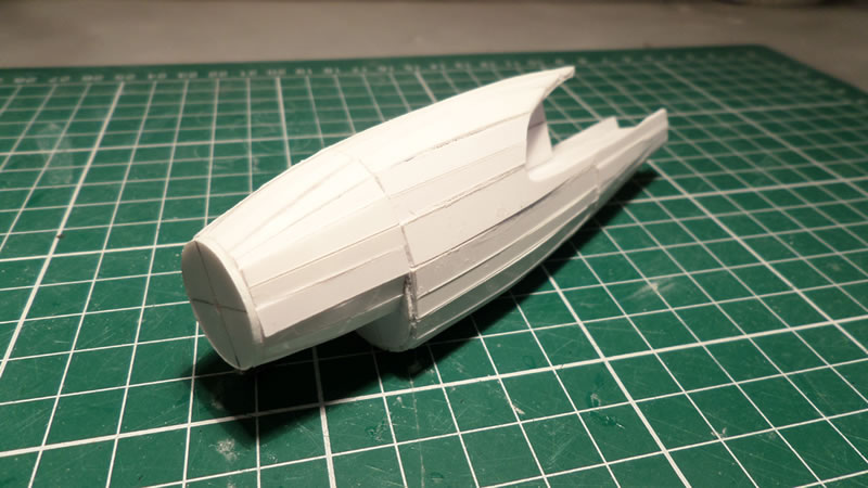
As one has to start somewhere, I decided to deal with the nose first. The building was initiated with my now-usual method of plank-on-frames, gluing 2mm-thick plastic strips on frames, following the drawings I had beforehand glued on a plastic profile.
As a side note, given the retail price of Evergreen strips, I produce these strips myself by cutting them out of polystyrene sheets.
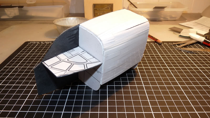
Here is a view of the original strips, glued with CA glue:
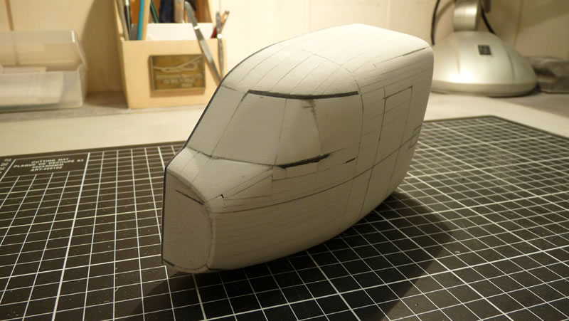
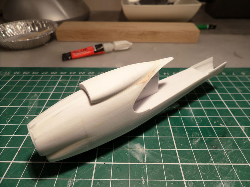
…then sanded following the aircraft profile. The inevitable gaps between the strips are filled afterwards with putty:
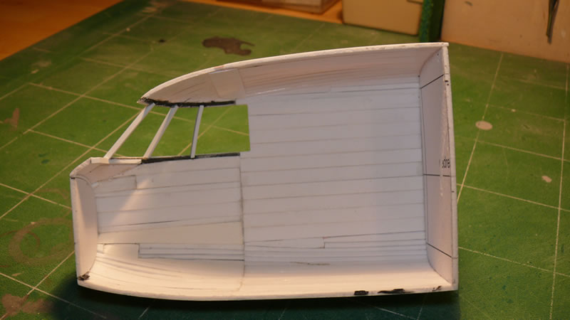
In the end, I removed the profile plate, and the frames, to get an empty half-shell. It is a lot stronger than a vacformed one, as it is a lot thicker. The only drawback is the final weight for a model measuring 80cm. We will see it later, but at the time, I did not know it yet…
Fitting the Cockpit
When the two nose halves were completed, fitting the cockpit could begin. It is not very difficult, provided you have some good references. But I was well covered in this area.
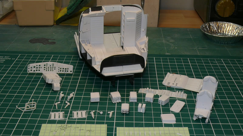
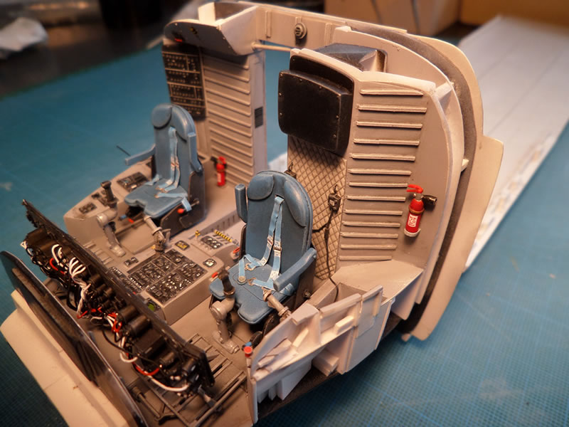
I have often been asked how I do a part. My systematic answer is that I simply try to approach the original by asking myself how a given component or sub-component is made-up in real. This is the simplest of techniques. So I build each part bit by bit, then glue it it in its final position. You can see on the next pic the seats, the various black boxes or levers or the instrument panel that will make up the cockpit.
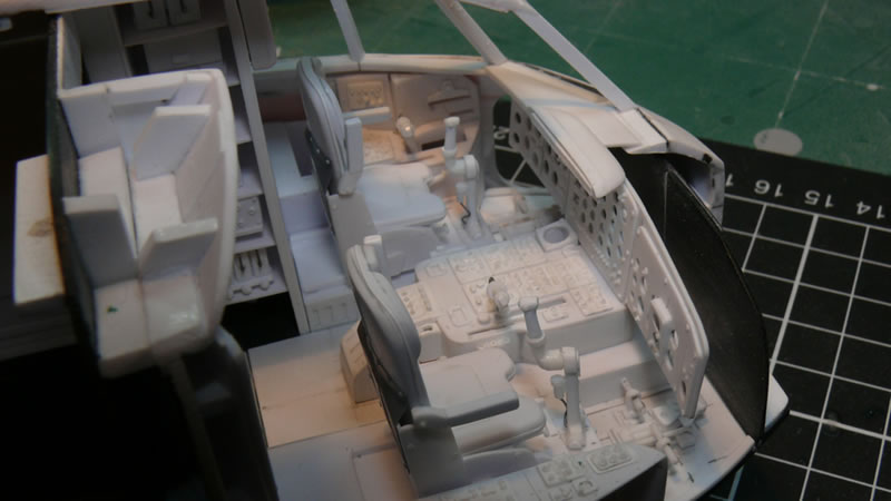
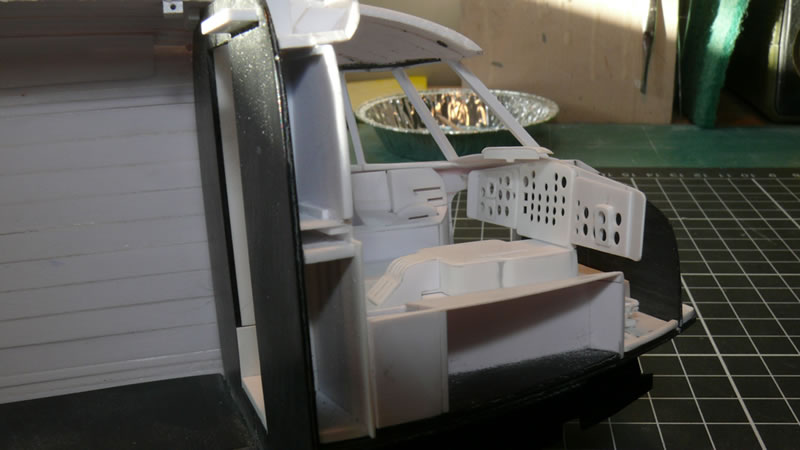
They are now fitted in place. You can notice one of the peculiarities of this incredibly manoeuverable aircraft: the pilot has a fighter-type joystick, and a single throttle lever. As the four engines were connected via a drive shaft going from one wing extremity to another, a single throttle was enough. A HOTAS ahead of its time!
The nose of the model includes the compartment just aft of the cockpit, furnished with a small lavatory and a few water jerrycans. This was a fairly rustic fitting on this prototype!
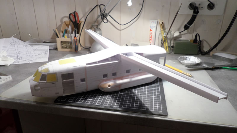
Building the Fuselage
Given the size of the model and never-ending forthcoming manipulations, I decided to split the whole in four parts (nose, central fuselage / loading bay, rear end, wings and engines), that would be assembled only in the end.
Nothing particular about building the rear end: I used the classical method of a profile on which frames are positioned, to be later covered with 2mm-thick plastic strips.
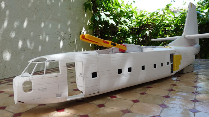
The central fuselage was done in the same way, and you can see here the three components assembled "for the picture". This allowed me to get a feel for the overall volume, and gave me a morale-boost on this long-haul endeavour…
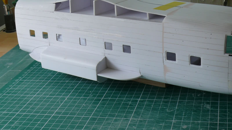
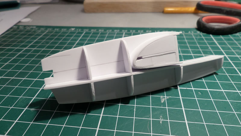
I then added the main gear nacelles, which are also divided in three parts: the central bay, and the front and rear fairings. To give them some roundness, they are preformed using a resin that is sold in blocks (the yellow-ochre part on the pic) that is called "LAB" in France and was given to me by a friend who was also a professional modeller: Jean-Michel TROCHAIN. Sadly, he is deceased since, and this model is dedicated to him. This resin is easy to work with and sand, and is very strong.
The resin parts are then covered with plastic strips to keep some continuity for the whole
.
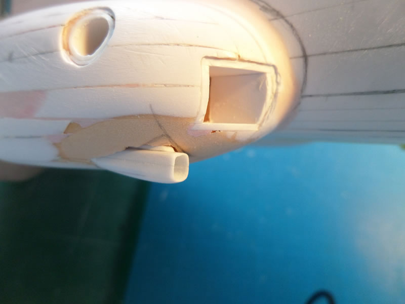
The landing lights recesses are then carved in the nacelles. When time comes, they will receive the lights of the aircraft.
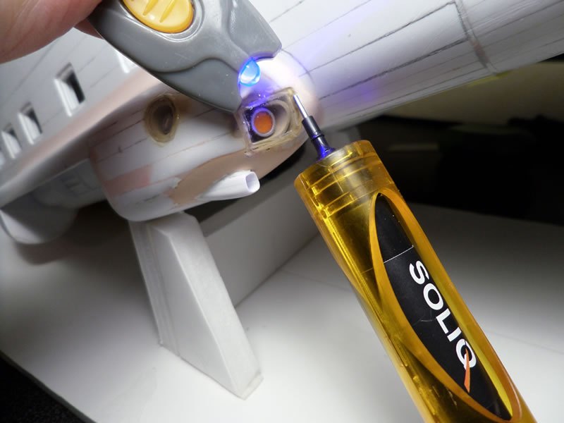
The landing lights are finally faired over with some thin (0.5mm) perspex sheet, suitably heat formed on a plug to match the compound shape of the nacelle. The clear parts are then glued and the seam filled with a UV-curing clear resin called "Soliq" in France. I suppose this product can be found outside France, but I do not know under which trade name [It is in fact Bondic in other countries – translator's note].
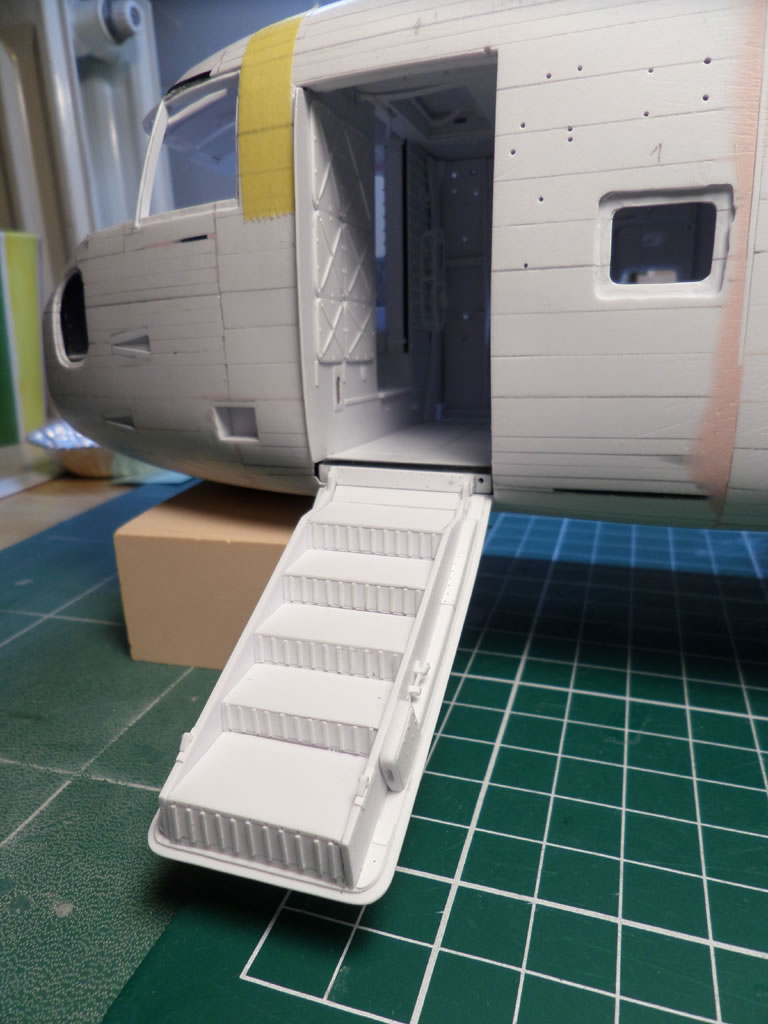
The Portholes and the Front Door
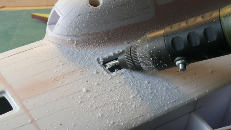
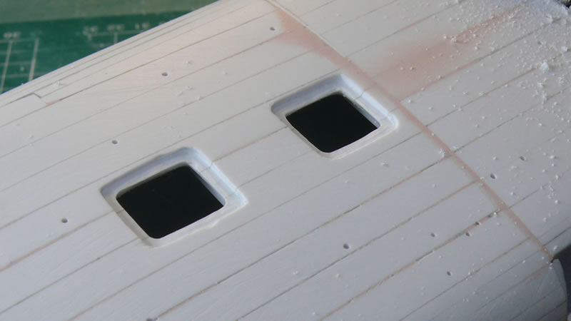
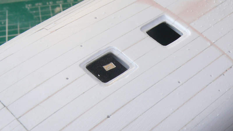
The portholes positions were drawn on the fuselage, then cut away. The holes were then ground further with a small burr on a mini-drill to allow to insert a perspex window that will be faired in the fuselage.
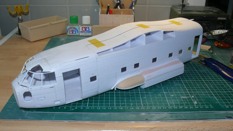
After producing a lot of sanding dust, I gratified myself with a more delicate work by producing the front left door, with its integral stairs. It's relaxing and a good change from sandpaper!
The Wings and Engines
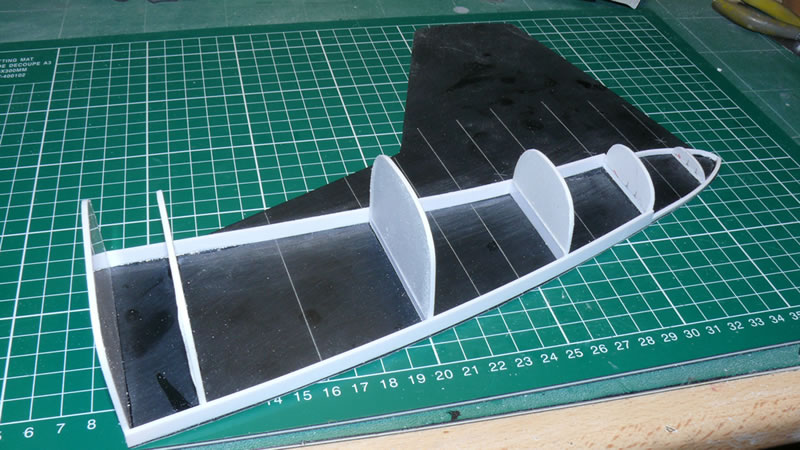
As I stated above, I think that the simplest way to make a part is to be inspired by real-size practice. Thus how is an aircraft wing built? One or more spars with stringers, and the whole subsequently covered with a sheet of metal. Well, let's do the same in plastic!
Here is the wing mainframe plugged into the fuselage. In fact, I hoped I could make the wings removable for transport, but the very complex shape of the Karmann fairing made it impossible in the end. I was forced to glue the wings in position, which gave me a span of nearly 80cm. Naturally that made transporting the model more complicated.
The wing box was relatively easy to build. The only thing to be very careful about is to respect the somewhat pronounced dihedral, which helped to ensure proper ground clearance for the outer propellers.
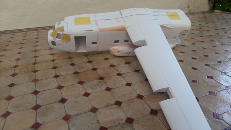
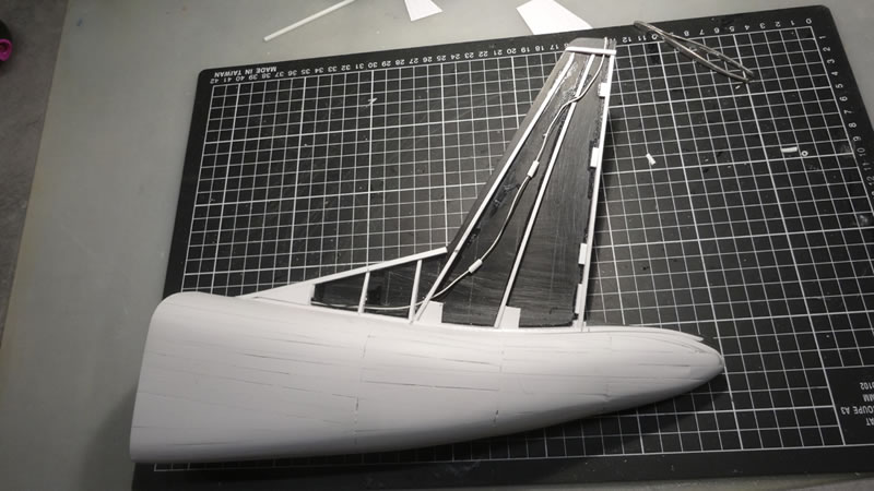
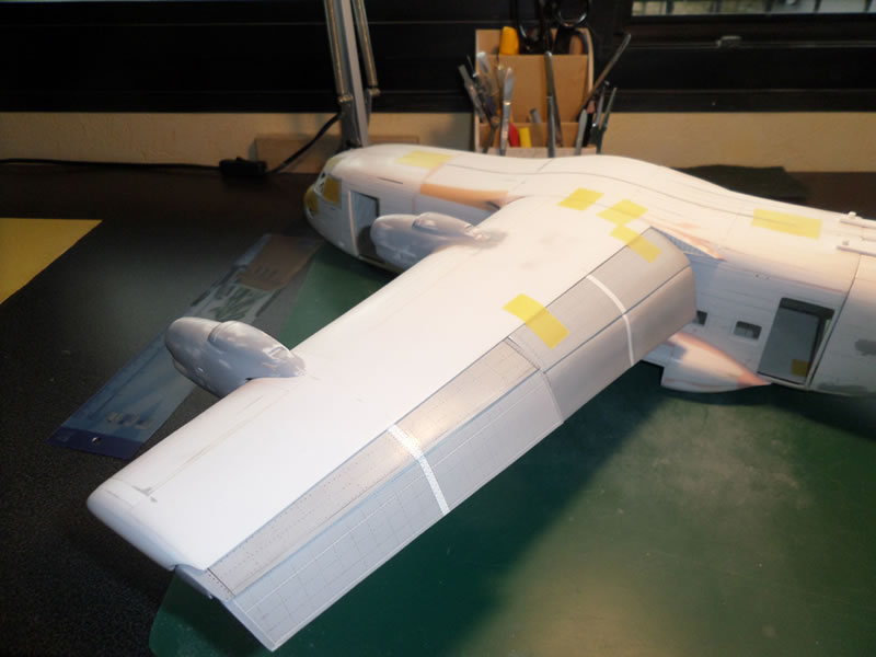
And now the wing fully covered, with the four positions for the engine nacelles.
"Don't change a winning team" is a famous saying in French. The engine nacelles were done in the same way as the rest of the fuselage: frames and plastic strips. As these strips are 2 mm thick before sanding, all the measurements must take into account the added peripheral 4 mm. It's just some arithmetic gym, and you get used to it very quickly.
I was asked why I did not do just one nacelle, then cast the other three in resin. The main reason is that the four nacelles are different because of the wing dihedral, and the left / right symmetry. Only the font part of the nacelles was identical between the four. I thought it was easier and above all faster to make them in plastic card.
One nacelle before sanding:
…and after. The benefit of using 2 mm thick strips is readily apparent here: it allows to fair-in the profile fairly easily.

The four engines are now in place. And the model has gained some weight. It weighs now more than 1kg, and it's not finished. We will see further down the impact of this bulk.
The Landing Gear
I don't know whether it's shared by other modellers, but I always loved building landing gears. These are complex elements who reflect the thinking of engineers who need to build strong, efficient, and yet light. Furthermore the landing gear of the Breguet 941 had to withstand landings on rough, unprepared, ground. A real challenge for engineers.
In the beginning, my idea was to show one of the landing gears through an open maintenance hatch. As the building progressed, I realised this would not be a realistic situation, and I gave up the idea, but only after I had done some major detailing of the front and main landing gears. Too bad! At least I had fun, and I know now how they worked, which the most important for me. And I still have pics left!
Given the likely weight of the model, all the landing gear legs are reinforced with a metal rod. But if I had to do it again, the whole landing gears would be in metal, as the model will weigh some 1.6 kg in the end. It's funny to think that this is the first model that I have been weighing regularly all along its building.
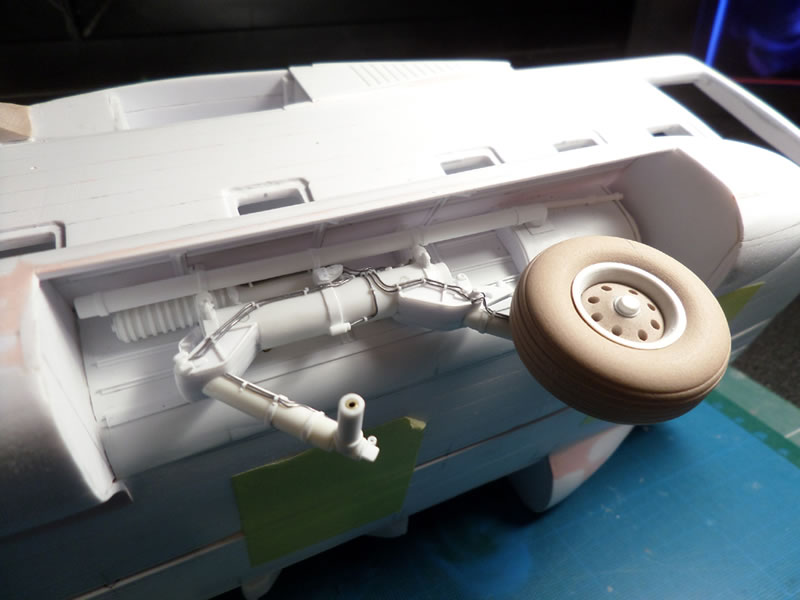
The left main landing gear set temporarily in place. Unfortunately, once the gear door is in place, nothing is visible anymore:
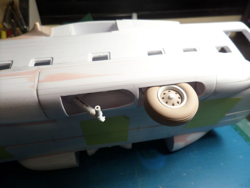
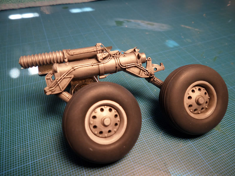
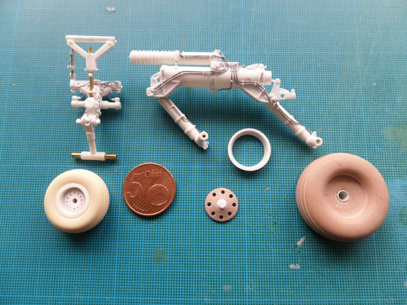
Just for the record, here is the left main landing gear, equipped with all hydraulic lines. I turned one wheel on a lathe using "LAB" resin, then the other wheels were cast using a classical two-components resin.
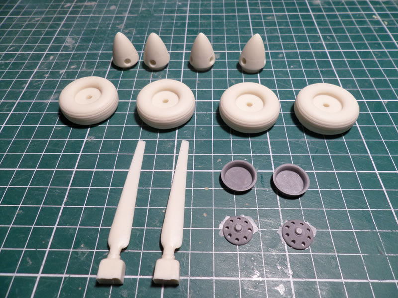
This casting operation was used on the front wheels, the propellers bosses, the wheel rims and the 12 prop blades, as can be seen underneath. These are the only parts I have cast.
Mobile Areas
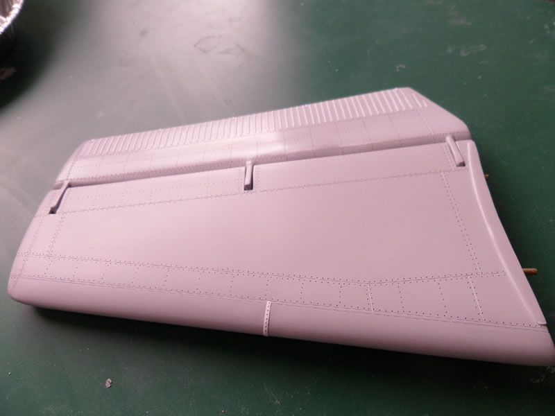
The mobile areas are made up of the stabilizers, the rudder and the flaps. The first two do not need further comment. In this scale, we are getting close to RC-models techniques, and the inverted profile of the stabs (more rounded underneath) has to be treated with care.
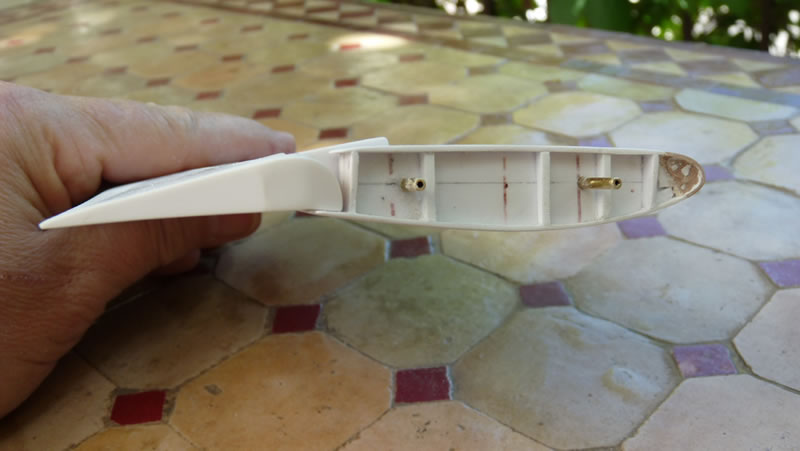
On the other hand the flaps are very important to get the right final look. To be able to achieve its landing performance, the Breguet doubled its wing area when extending the flaps (it did not have any leading edge slats). They could be extended up to 105°, and to me presenting them fully extended, as many ground pics of the aircraft show them, was paramount.
This is where I stumbled upon an issue: I had no documentation on the position of the flaps mechanisms when fully extended. I had pics of the upper wing in this configuration, but none of the bottom wings, or they were in a dark shadow. I resolved to show them with a lesser extension (well, that is still 70°), but here I was sure of my references.
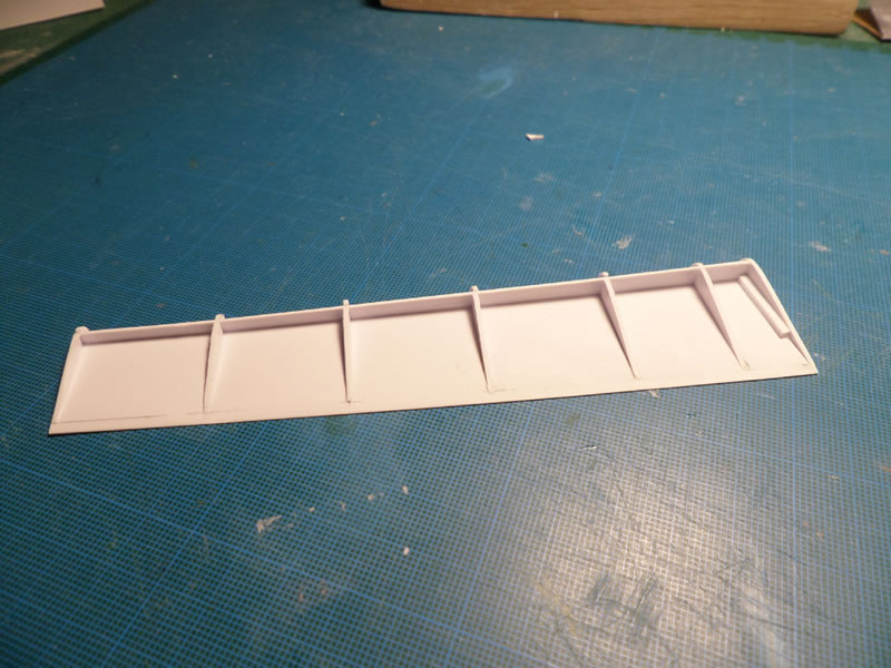
The flaps were built following the real ones, with a spar, some stringers and plastic card to cover the whole. I had to redo them three times before I could call myself satisfied, which slowed the building somewhat. But at least I am happy now…
One of the difficulties of the flaps was to ensure o good representation of the slots between the flaps, as this was a key factor for their efficiency. You can see on this pic that flaps occupied the whole trailing edge, and were integrally in the washout of the four props. This is what is was called a "blown wing" and it brought an incredible amount of extra lift. The aircraft could fly at 100 km/h without any problem!
Fitting the Inside
My building method relies heavily on sanding, and therefore generates a lot of dust. Therefore I start the painting as soon as I have finished all the various parts. I felt I had reached the stage where I could start the painting. I started painting the cockpit, painting the various bits one by one, and then gluing them in place thanks to the tabs I had added to each one.
You will notice that I went as far as wiring the instruments, but sometimes my will to do "like the real one" pushes me over the top…
The different colours were deducted from the important references I had accumulated, including the original maintenance manual of the aircraft, but above all by the pics I took at the Bourget Musée de l'Air some twenty years ago.
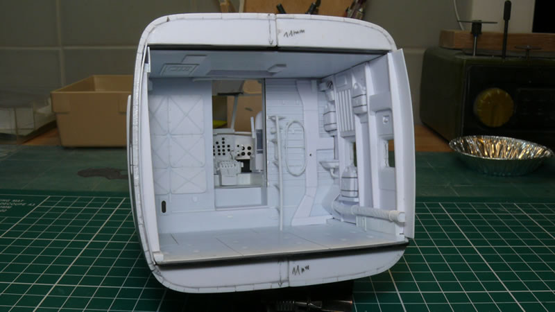
The loading bay came next, and the small lavatory got its gloss white color. The hatched parts on the windows are just masks to protect them during the painting stage.
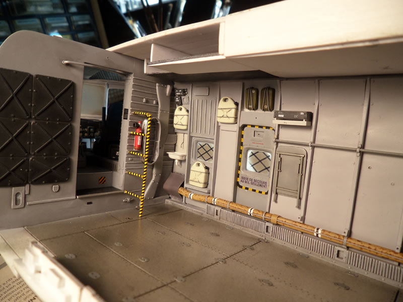
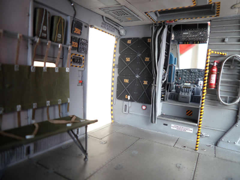
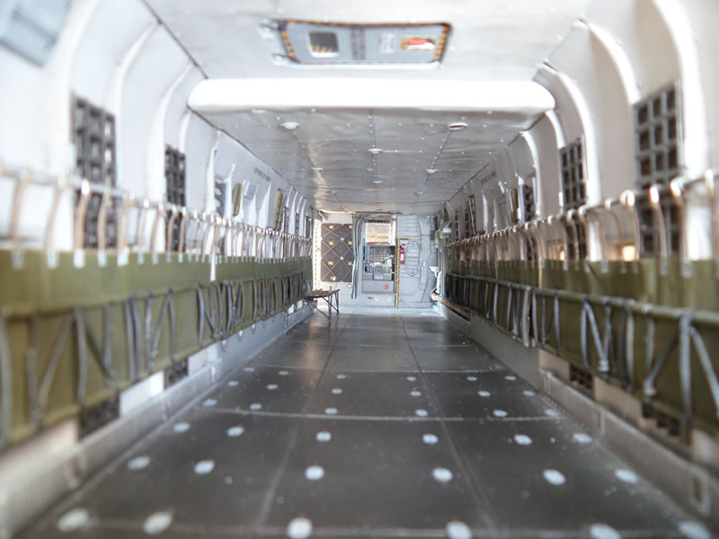
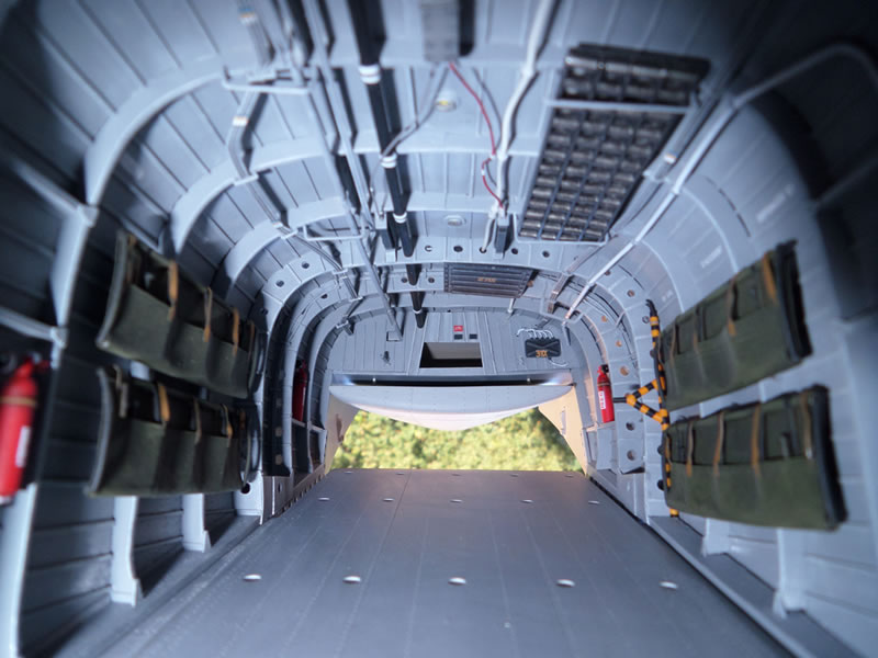
Here are other pics of the bay, with the folded benches, except for just a small portion in the front left, as if the loadmaster had just sat there.
And finally the fittings of the rear end, without any padding, and with all the frames visible. This concludes the detailing of the inside. The loading ramp is closed here of the pic, but it will be open in the end, as this will contribute to offload the landing gears somewhat, being an extra support for a model that has grown some more weight with the detailing of the bay and of the inside padding.
Puttying the Model Before Painting
Building the kit with "planks" has one drawback: it creates a lot of seams which must be puttied then sanded. I generally use an automotive body-putty. It works well, and is cheap, which is not a minor point considering the area to be puttied. When this is done I use an automotive finishing putty in spray cans to blend the whole. Even if the label on the spray can says it dries in one hour, I give it a lot more time: three or four hours and even sometimes a full night when I sprayed a heavy coat.
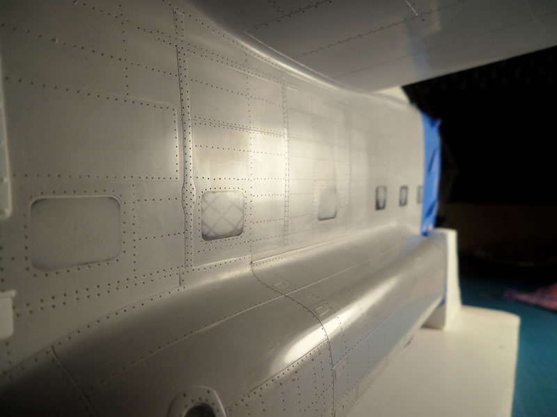
It is then sanded with wet-and-dry sandpaper, starting with 600-grit and finishing with 2000-grit. The whole surface looks then like a mirror.
I then scribe the structure lines in the thickness of the putty, and then the rivets positions are drawn one by one (yes, one by one!). I will then drill each rivet with a 0.3 mm drill. I prefer this method over using a riveter wheel, that I possess nevertheless. I think the precision is far greater this way. Of course this implies a considerable amount of work, and the reward is only at the end, when you add a wash to the lines and rivets.
As an illustration, here is a rear stab done in the way I just described. You cannot see the various components. The final appearance is smooth, and the rivets visible. The part is ready to be glued in place.
I did the same with the fuselage, but here the prep work can be counted in weeks (months?) and the rivets in tens of thousands…
Here is another tip. I used a Silhouette Cameo cutting plotter. I am not sure the way I used it was in its original designing brief, but why not stretch the limits of any device ?
Thanks to the Silhouette, I could design masks before I sprayed some thinned putty over them. The end result when you remove the masks is a thin overthickness that represents a structural reinforcement, as on the real aircraft. In our scale, this gives a very realistic result, as can be seen on the pic below.
I also used the Cameo to represent the seal around the windscreen. The Cameo was a great finding during the building of the Breguet.
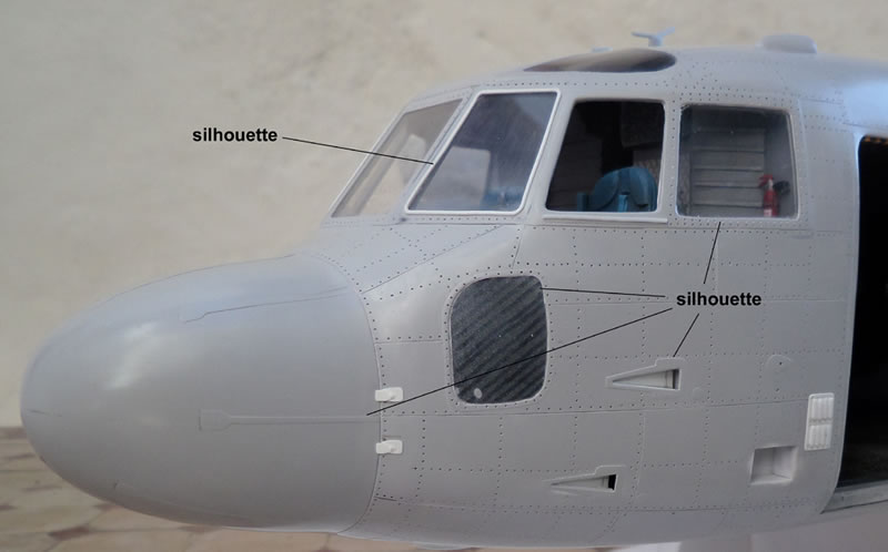
This is another pic of the fuselage that shows how smooth a surface can be achieved, and then how you can add, using masks cut on the Cameo, a reinforcing girder, a wing Karmann fairing, a metallic repair patch, the landing lights seal, and even the commands for the main gear well opening on the sides of the main gear fairing. It is really a multi-use tool.
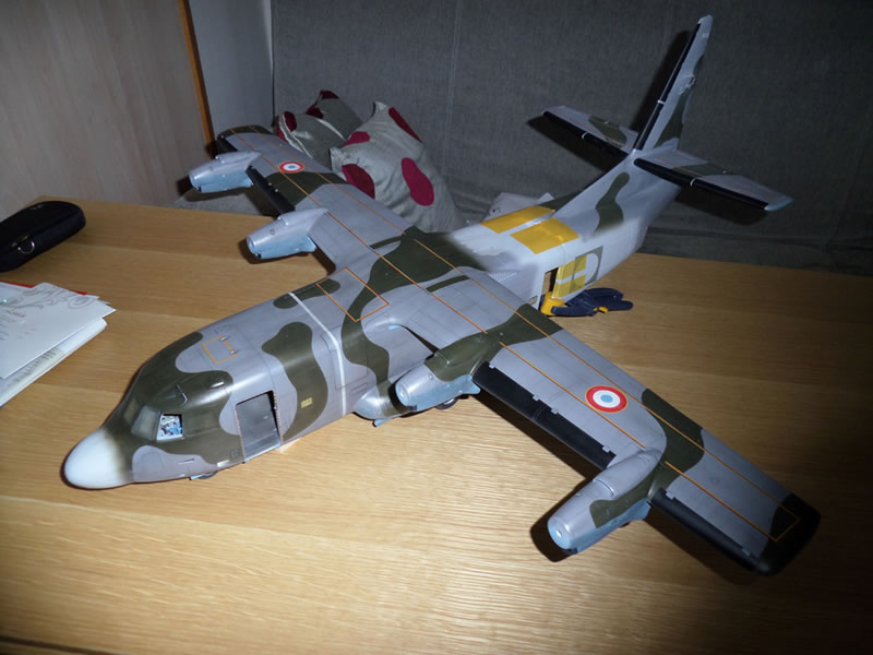
We are now nearing the end with the final painting stage. The camouflage had sharp edges. It is drawn and masked using standard methods, then sprayed on. I realised an astonishing fact at this stage. The four aircraft had four different camouflage patterns. I had to really look closely at the various pics to draw the camouflage pattern of "NA", the first prototype. The French roundels and the "NA 62" codes were spayed using masks cut on the Silhouette, which was it has been designed for. On the pic below I have just glued the rear fuselage. After sanding the seam, the paint was blended between the two parts.
Here is the model almost finished (it misses the wire antenna). The prop blades are in place, as are the access doors. I drew the specific (for the outside and the inside) decals on Photoshop, the sent them to a printer. This ensured a better quality, and on top of it a lot of them are white, and I could not print them at home.
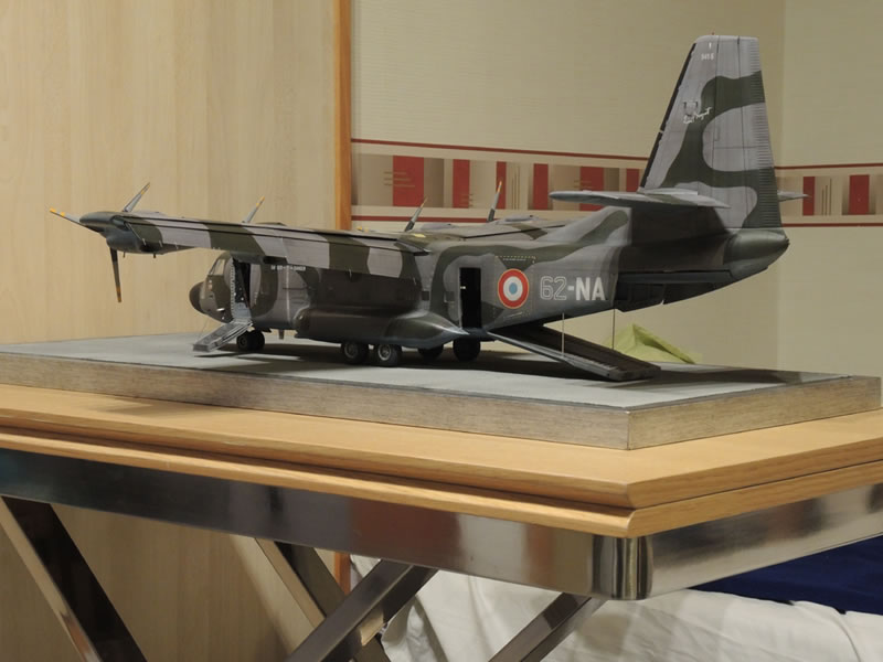
Rear view of the model before its departure for Telford. Please note the rear ramp in the down position. As I said above, this part contributes to help the main gear support the model which weighs 1.6 kg in the end. If I had to do it again (no! no! I don't want to!) I would change two things: I would lighten the model as much as possible, and I'd do the landing gear all in metal, to be safe.
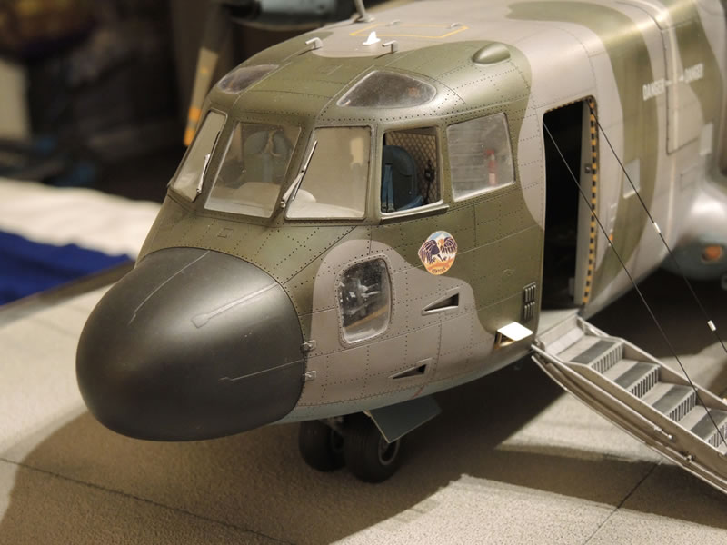
A close-up of the front end, that shows to good advantage the benefit of spending so much time on the rivets, and the final appearance of the areas where I used masks cut with the Silhouette.
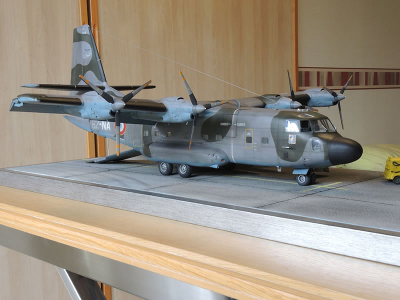
And a final view of the completed model:
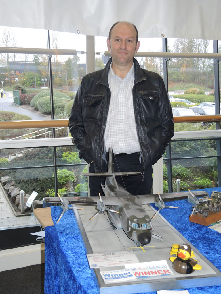
In conclusion, here I am with my Bregeut at Telford 2015. I am of course very happy that my work was recognised and received an award as "Best Aircraft Model" there. I am of course flattered as there were so many outstanding models.
But the biggest satisfaction comes from all the talks and the signs of friendship I was shown, coming from everywhere. I took them in gladly, and I hope my work will encourage others, notably the younger generations, to get started in a technical hobby that is so enriching in the end;
As I said in the beginning of this article, I ended saying I will never endeavour again something as crazy…
But modelling is a kind of addiction, and there is no denying that the next subject is already in gestation [A Nord 1500 Griffon – translator's note].
And finally, if I had one last thought to share with you, I would say that scratchbuilding is just one way of finding enjoyment in our hobby. And the other ones are just as legitimate.
Happy modelling to all and best regards from Paris.
This article has been translated into English from French by Hubert Boillot.
© Emmanuel Gato 2015
This article was published on Monday, November 30 2015; Last modified on Monday, November 30 2015