
1/32 Trumpeter F-105G Thunderchief “Wild Weasel”
By John McCormick
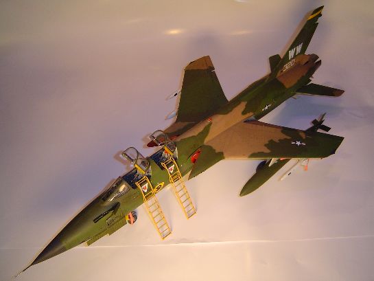
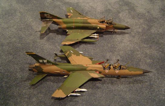
I read all the reviews, but I scoffed. I saw the photos, but I knew better. After all, I’ve been building 1/32 scale planes for 30 years or so. However, when I finally bought Trumpeter’s F-105G Thunderchief “Wild Weasel” and opened the box, I realized I had been fooling myself. This kit is BIG!! The length of the finished kit is about 26 ½” long, and it makes my 1/32 scale F-4E look like a 1/48 scale!
This is my second experience building a Trumpeter kit. I have built their A-10A Warthog and, like the A-10, the F-105G has its strengths and weaknesses. The pieces are nicely molded with recessed panel lines and rivets, and the selection of armament is almost overwhelming (the accuracy and detail of the armament is much better than the A-10). The decals are from Two Bobs, and they are a high point of the kit.
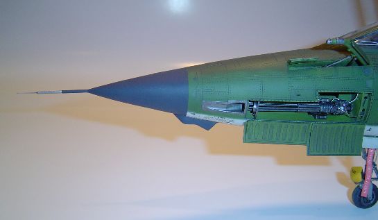
The outlines of the vertical tail fin and radome are inaccurate. I used the Cutting Edge corrected fin to replace the misshapen kit fin. Cutting Edge also has a corrected radome, but I elected to fix that myself with putty.
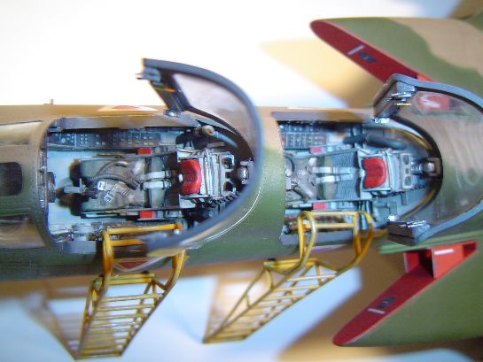
The cockpit is somewhat sparse for a model of this scale. For a kit that is priced like a Tamiya model, the cockpit detail is more like a Revell kit. Both Black Box and Verlinden have cockpit sets, but I was somewhat intimidated with the Black Box set when I saw an on-line review. It has a lot of small resin parts, and I did not think I was up to the challenge. Additionally, since the Black Box set is about $40.00 U.S. compared to Verlinden’s price of $18.00 U.S. and Verlinden includes gun bay detail, I chose Verlinden’s set. It just goes to show that you usually get what you pay for. The Verlinden kit is a BIG disappointment. While it is an upgrade to what is supplied with the model kit, Verlinden’s cockpit is inaccurate, not very detailed, and fits horribly (boy, does it fit horribly).
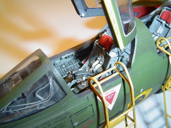
Fortunately, I found a great article on the web at www.craigcentral.com. Scott Craig did a great job building his F-105G and included many photos of his kit during the assembly process. Scott used the Black Box set and, using his photos as a guide, I set out to upgrade the Verlinden set as best I could. I added plumbing, additional detail and wiring to the ejection seats, and spruced up the “dashboard” area under the windshield. I also scratch built some details inside the canopies.
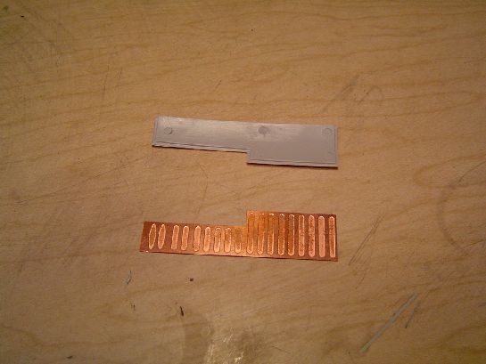
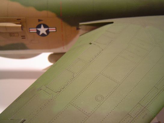
The Verlinden set includes some photo etched pieces for the cockpit as well as the gun bay, including a piece to add detail to the inside of the gun bay door. However, this piece is actually manufactured mirror imaged to the kit door (see photo)! I ended up cutting the kit door into 2 separate doors (which I think is accurate anyway) and did the same to the photo-etched piece to make everything work. Since the instructions included with the Verlinden set make no reference to any of this, I can only imagine that anyone who purchased this set is as aggravated as I am.
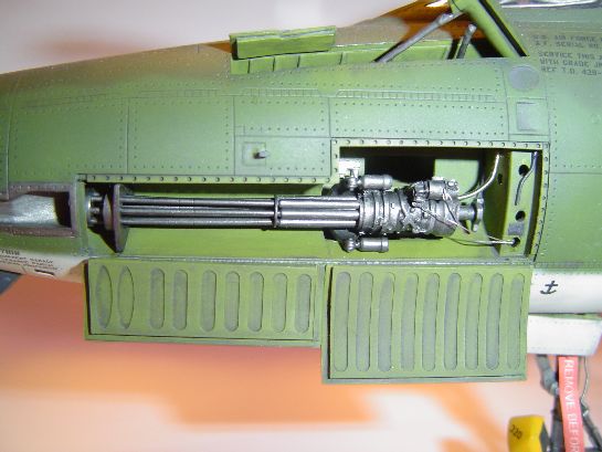
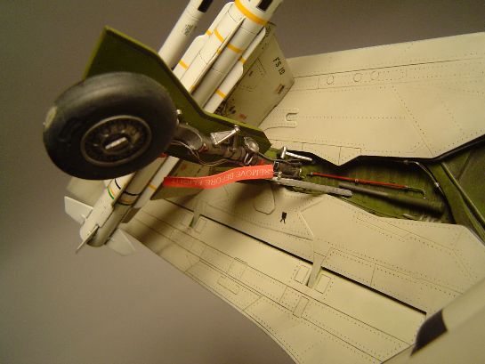
I had read that the main landing gear is too weak for a model this big, so I bought metal gear struts from Scale Aircraft Conversions. I strongly recommend going this route to anyone attempting this kit. Additional details to the gear struts and wheel bays, such as brake lines, hydraulic lines, and electrical wires, were simulated using copper wire and guitar strings. In hindsight, I probably should have painted the wheel and gun bays white instead of the zinc chromate green per the instructions, but it looks OK so what the heck.
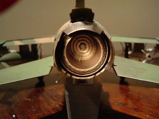
The kit includes a highly detailed engine. Unfortunately, you cannot see 90% of it once it is installed in the fuselage. Therefore, I did not bother using any of the parts 2” forward of the exhaust. The afterburner section is molded as four separate sections, creating four nasty seams. These pieces are also riddled with ejector pin marks. The end result is a very unsightly afterburner section. To correct this, I used an Excel spreadsheet on my computer to create a black lined rectangle (to simulate the raised ribs) and printed it on photo quality paper, filling the cells with gray. I then oversprayed the paper with a thin coat of MM metalizer Burnt Metal to make it look more metallic. I trimmed it to the appropriate circumference, rolled it, and inserted into the afterburner. It’s a two dimensional solution to a three dimensional problem, but it looks much better than the kit pieces and leaves only one seam at the top.
There is an option to display the bomb bay in the open position, revealing the fuel tank that was usually carried there. I left it closed and left all these parts out of the assembly to save on weight. In place of the bomb bay parts, I reinforced the fuselage with a couple of pieces of sprue.
The kit is supposed to have moveable control surfaces, using photo etched hinges and metal rods. The long and short of it is that this system does not work well, and I recommend gluing the control surfaces in place. It will save a lot of fooling around. The spoilers are molded as separate pieces (five per wing), giving the modeler the option of positioning them in either the up or down position. It is my understanding that the spoilers are only in the up position when the plane is landing, so the logical choice is to glue them in the lowered position. Be warned! The fit of these pieces is bad, and the subsequent gluing, filling, and rescribing of the hinge areas is both tedious and time consuming.
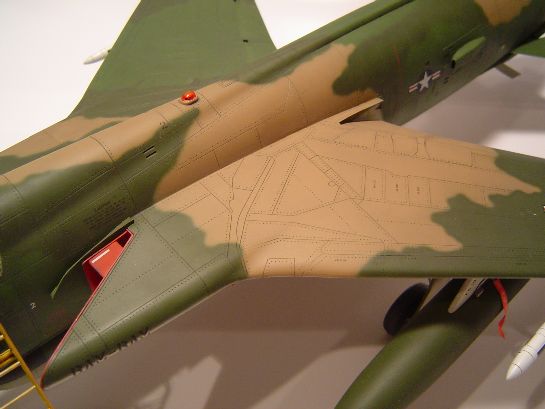
Other than the spoilers, the fit of the kit parts is excellent and assembly was quite quick. Before painting, I tried my luck at pre shading. However, I cheated and used a black Sharpie marker to shade the panel lines. It did not work well at all, and the gray on the underneath portions of the plane yellowed anywhere there were marker lines. I had to paint a little heavier than I would have liked in order to cover up the discoloring. I was fortunate that it was an easy fix, and it was a good lesson learned. MM enamels were used for painting, and the only color I modified was the medium green. It was lightened up slightly using yellow and bright green. All camouflage was airbrushed freehand.
A gloss coat of Future was applied before decaling. Future works great for this, and I recommend it to anyone who has not yet tried it. At first, I was very reluctant to apply a floor polish on my precious babies - I mean my models. I kept thinking, “What’s next, toilet cleaner to simulate weathering?” But Future does the trick with no problems.
As I previously mentioned, the decals are a real high point to this kit. They went on beautifully and I had no silvering whatsoever. Believe me, if I can’t get them to silver, nobody can. Because I used the Cutting Edge corrected fin, the yellow stripe at the top of the fin was too short. I had to use scrap pieces of yellow decal to extend the stripe to the back of the fin. Once the decals were dried, a sealing coat of Future was applied over them. I then gave the plane an overall black wash using opaque, which is a water-based product used in the printing industry. I thinned it down with water and added a little detergent soap to get it to flow into the panel lines. The excess was wiped off, and I oversprayed the entire kit with a very watered down solution of Polly Scale Dust to soften the colors. Once everything was completely dried, a final coat of MM Dullcote was airbrushed on to finish the painting process.
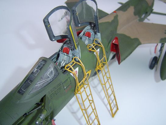
To finish things off, I scratch built FOD covers for the intakes, and boarding ladders were made from plastic rods. RBF tags are from my color printer. Any colored lights were tinted using the appropriate colored Sharpie marker, then sealed with a coat of Future.
All in all, it’s a great kit, and a very quick and easy build. It’s not without its own little irritating shortcomings, but what kit isn’t? It took me about 3 ½ months to complete, which is a record for me. I must thank my wife, who allowed me a “guilt free” build. Alas, the party’s over, spring is here, and yard work awaits.
References
- Squadron Signal Publications F-105 Walkaround by Ken Neubeck
- www.craigcentral.com
- www.aircraftresourcecenter.com
- www.largescaleplanes.com (what else?)
© John McCormick
This article was published on Wednesday, July 20 2011; Last modified on Saturday, May 14 2016