
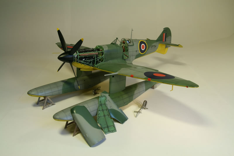
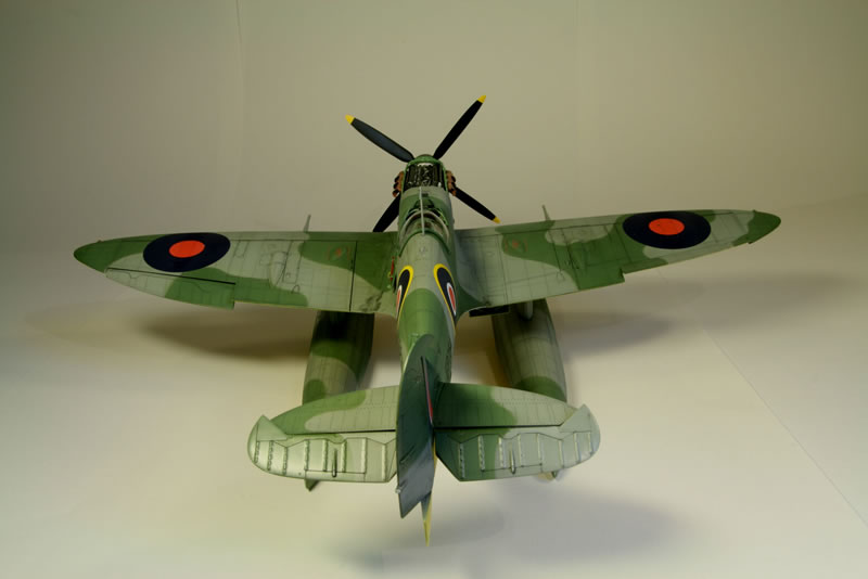
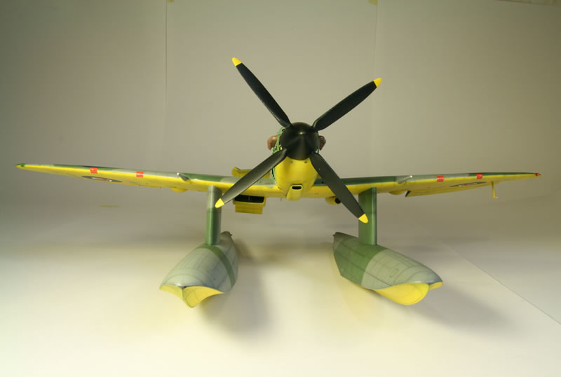
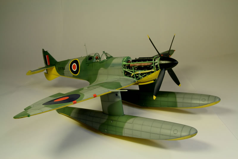
Trumpeter 1/24 Spitfire Vb Floatplane
By Max Otten
Introduction
This is the story of the making of the Spitfire floatplane. Started somewhere in 2007 and not finished till 2010, it was not a project that went smoothly. I made a number of mistakes. Some were due to inexperience (it was only my second project with a lot of detailing done), some had other causes. My most serious mistake was presuming that for a 1/24 kit – with a lot of detail highly visible – Trumpeter would have done their research properly and so superdetailing would mean adding stuff, not major surgery to correct errors.
Some things struck me as odd from the start. The pilot’s seat was weird. No room for a parachute, and the pilot seemed to be sitting on wood planking. And the firewall behind the engine also was rather strange and didn’t look like anything I had seen before. I have made a fair number of Spitfires, mostly 1/48, and many of those are far superior in detailing than the floatplane kit. There are also excellent detailing kits for engines and cockpits on that scale.
Research
The Spitfire is probably the plane about which the most has been written, with a lot of excellent reference material. Still, it isn’t all as easy as it seems. The Spitfire went through a lot of Marks and they all differ, sometimes subtly, sometimes with major differences. So there always remain questions and uncertainties if the reference material does not cover the exact Mark you are interested in. Additionally, a lot of the references are based on Spitfires actually flying today and there it is difficult to figure out what parts are original.
There is no Spitfire floatplane left, so it is impossible to establish exactly what they were like. We have to do with a few black-and-white photographs. The kit covers three of the floatplanes which were Mark V conversions, W3760, EP751 and EP754. Of the latter two I only have reference photographs as they were at the Great Bitter Lake in Egypt where they underwent trials. The original intention was that they would be used to harass the Germans from shifting bases on the Greek Dodecanese islands. In the end, it all came to nought because the Germans were too well established there. Besides, the floats turned out to leak so the planes had to be taken out of the water daily, which would not have been viable in real action.
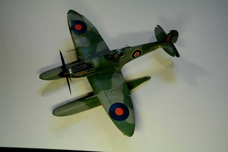
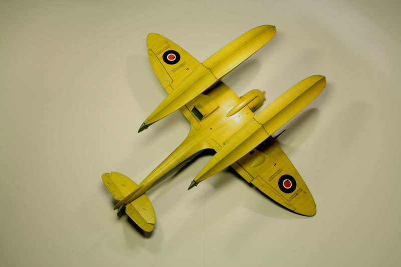
The color scheme is unknown. Prototypes would have been painted at least partially yellow. The undersides of EP751 and EP754 do appear to be quite light-colored, with an upturn underneath the tail which is not normal for the standard camouflage scheme. But the planes are lacking the letter P in a circle. The Trumpeter color scheme indicates yellow, in one reference I found light gray. I decided to stick to a yellow underside, partly because it makes a diversion from the normal camouflage scheme. I followed the kit instructions for the rest, using medium gray and a dark green (lightened with white). In the photographs you can barely see that there are two colors on top so I guess it is the best one can do. One thing I should have done much earlier is visit the Royal Air Force Museum in Hendon, because that turned out to be most useful. While there, I took hundreds of pictures of several Merlin engines on display and made some drawings that helped me understand what it was all about. Better still, when I chatted to one of the museum attendants, he directed me to the research department. And they were extremely helpful, providing photocopies of a number of diagrams from technical manuals on the Spitfire V with lots of details such as cooling and oil systems, etc. Finally I do understand a lot about the engine, even though not all the knowledge did make it into the finished model.
What do we know about the floatplane? Essentially that it is a conversion of a standard Mark V. That has a number of implications for the engine, the firewall and, especially, the cockpit. As an example, the plane would have been outfitted for the drop tank so the controls for that must have been present. A lot of the superdetailing presented later is based on the basic Mark V material available.
Surface
The surface finish of the kit fuselage, wings and floats had an orange-peel like effect so I sanded it all smooth and polished it. I think the rivets of the kit are way overdone. Rivets on the fuselage would have been raised, not recessed. Those on the wings should be flush with the surface and generally in photographs are almost invisible. One thing that needed correction were the rivets on the panel over the fuel tanks, in front of the canopy. This plate has fasteners (as present on the kit) but no rivets at all, so I filled the rivets with superglue, and sanded and polished them flat.
The Engine
Phase 1
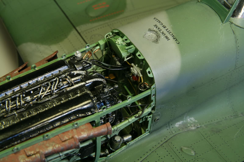
I planned to have the engine exposed, with the top and side cowlings off. The inside of the top cowling is difficult because the few reference pictures I had (from a Mk. IX, not a V) show it at a rather acute angle, with an obstruction (on the photograph, not the panel) in front of the air intake for the compressor. I thinned down the edges of the kit part, cleaned up the severe ejector marks, filled the slot at the back, hollowed out the reverse side of the top bulges and made the internal structure. I also glued small styrene rods (1 mm) on the inside where the fasteners are located. I noticed that the fasteners are missing on the outside at the front and back of the panel so I scribed those. Photo 2 shows it with the other cowlings.
Next I started on the engine assembly. And ran into a lots and lots of problems. In fact each step I took seemed to generate more problems. There is a lot of piping and wiring missing. Some of that is to be expected, but the coolant header tank has pins where a pipe should be connected, but no such pipe is present in the kit. And this one is difficult to scratchbuild as well, coming down from either side into a junction and from there to the starboard wing. There is a lot of other detail missing, like the quite prominent suppressor on the port side. The engine mount misses several struts. The bottom struts also run afoul of the bottom of the engine which doesn’t have the correct shape so the struts cannot be close enough together at the back end.
So I started modifying things. Looking back I realize that to a large extent the engine and the firewall are utter rubbish. I noticed minor errors like the number of reinforcing rods at the bottom, but I totally missed the major faults. The most problematic one is that the V-angle of the cylinders is off by a large amount (30° instead of 60). That makes the top of the engine between the covers much too narrow and gives other problems as well. In addition the supercharger isn't right. And finally the real cylinder blocks don’t run all the way back to the end of the covers, but there is empty space where the cam shafts run up. I did not modify that part and that gave problems later because it was difficult to fit the ignition cables coming from the magnetos.
As I was working on the engine I gradually I came to realize a number of things. I do have some excellent books on Spitfires but they tend to cover too many different Marks. You see a pipe in one photograph but can only see one end. And in a photograph of the other end but from a different Mark that same pipe isn't there at all. Even reference material on the same Mark may not be in agreement. It appears for example that the arrangement of the various items on the firewall changed throughout the history of the Mark V. Also, when you get a good view of the firewall, it means that the engine has been removed so it is very difficult to figure out how the various pipes and lines are connected between firewall and engine. Finally, the typical Merlin engine is painted gloss black which makes it really hard to figure things out as visibility of a lot of things in photographs is less than optimal and lines and pipes are difficult to differentiate from each other when they are all black. In the end, the best way I found to solve the problems was to try an understand what the various items were and then guess (or even trace in scanned-in and printed photographs) where goes what.
What saved me in the end is documentation on the Mosquito which had a number of excellent views of a Merlin engine plus a book with a detailed drawing of the Merlin 45. The Mosquito book is vague about the version of the Merlin but it looks to be close enough to the Merlin 45 to be workable. All in all I used about six books on Spitfires, plus books on the Hurricane and Mosquito.
Still, some things were difficult to establish with certainty, especially the electrical cabling near the firewall. Also the rods connecting the engine control lay shafts on the firewall and the corresponding controls at the back of the engine were impossible to establish as they cannot be seen on any reference photographs.
At that point I still was trying to figure out what is what and what goes where so I switched to the firewall first to see if I could make sense of it all.
Firewall
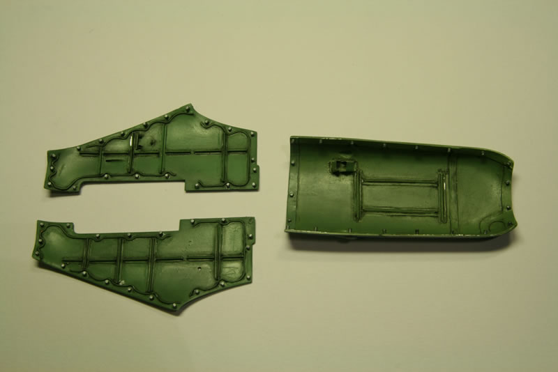
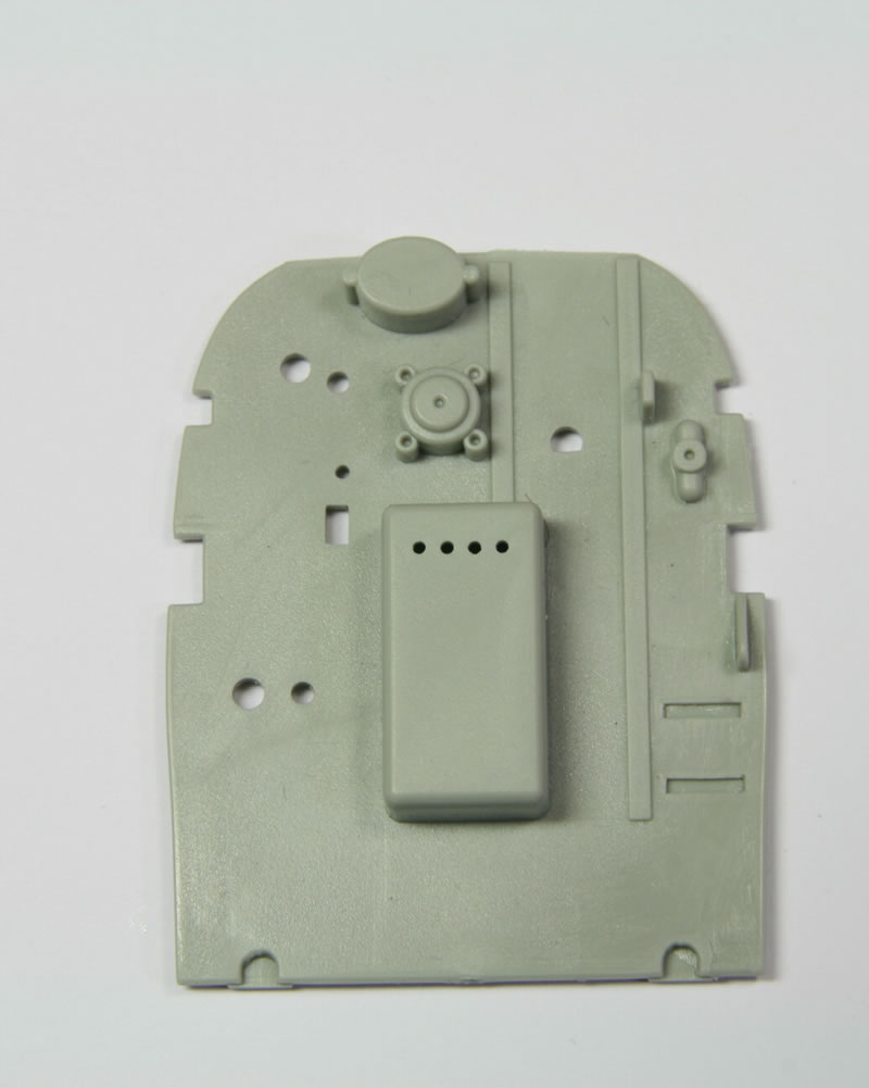
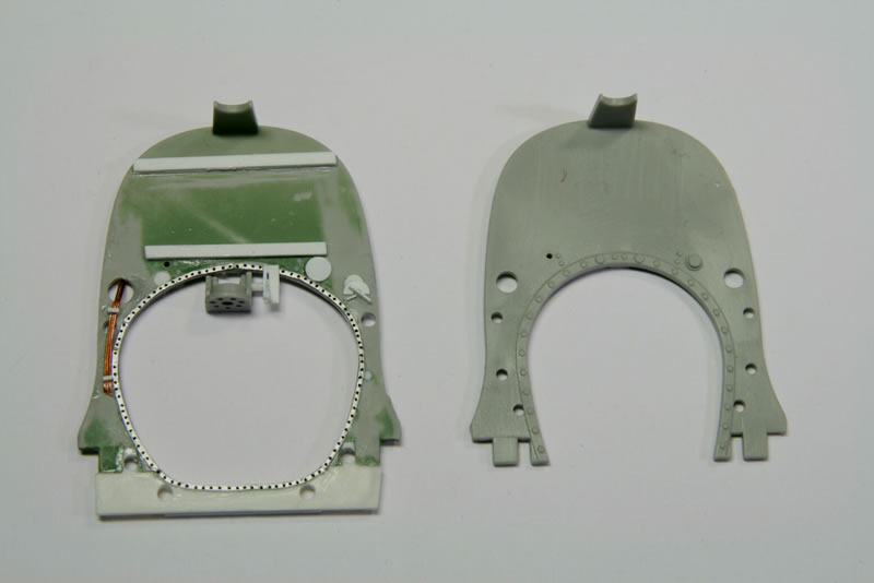
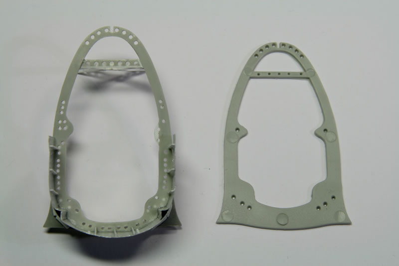
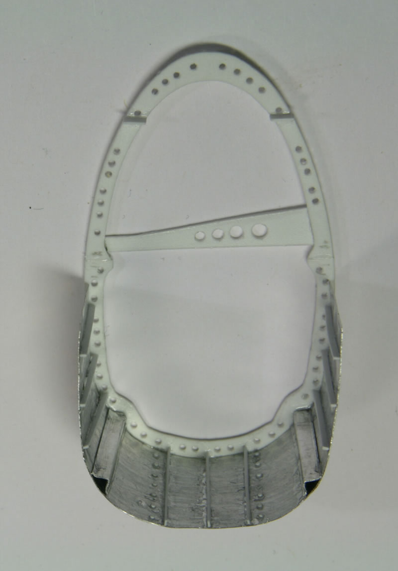
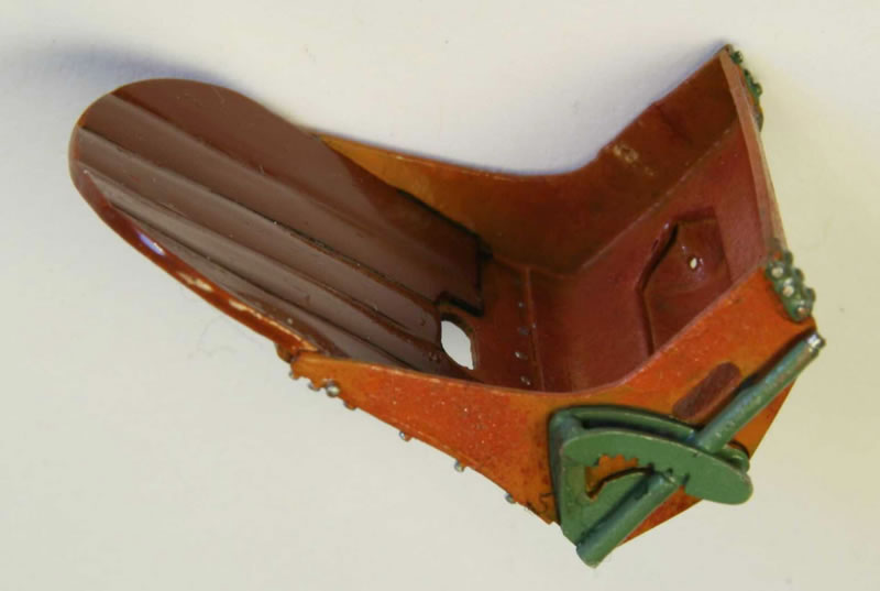
The firewall is another mess. In the kit it has a block-like protrusion at the center bottom which I failed to find in any reference material. The hydraulic fluid tank looks accurate in shape but is much too small. In the end I simply cut all detail off and filled the holes. Photos 3 and 4 show the original firewall and the end result.
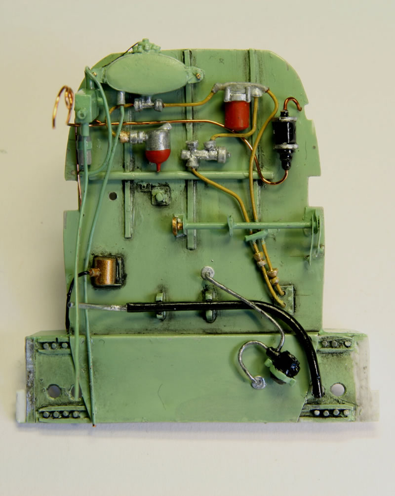
I made a computer drawing of the whole thing so I could easily modify positions and sizes as a kind of dry-fitting. I'm still not 100% sure the vertical dimensions are right though. Perhaps the distance between the wing-support structure at the bottom and the lay shaft in the center that holds the throttle connecting rods is off. In the absence of a photograph that shows the whole firewall from top to bottom it is difficult to be sure.
The bottom of the firewall is connected to the wing support structure inside the fuselage so I built that from sheet styrene with a sheet-metal cover plate. For putting in the wing-support structure I had to remove some material from the fuselage, which left that rather weakened so I glued in styrene plates as spacer behind the firewall.
The hydraulic tank is made up of front and back plates from sheet styrene to get the shape right. The front plate is sanded down to give it the required curvature. The two are connected by styrene plates inside. Sheet metal forms the rest. The remainder of the items on the firewall were made of disks of sheet styrene in different thicknesses (some reshaped to hexagons), sprue and metal wire.
Engine, Phase 2
I started off with the coolant pipe which took me several tries. The three-way junction is made from pieces of sprue glued together, with holes drilled where the wire from which the pipes are made goes in. Because the wire is so stiff (electrical wire with its insulation still in place – the only material I have with a suitable thickness), getting it into its proper shape pulled the junction apart a couple of times, so the final junction is the result of the second attempt and even that had to be fixed several times. And in the end, when it all had to come together, I found it interfered with the support bars for the engine cowlings so I had to do some judicious thinning there to get it into shape.
Cylinder Side Walls
The cylinder walls do have a lot of structure (well visible in Ref. 7, p. 76). The main problem of the kit's engine is of course that the angle is all wrong but at this stage I did not feel like ripping the whole thing apart so I made do. I made the side walls as separate parts on sheet styrene because that makes painting and detailing much easier. The plates were put on during final engine assembly.
Supercharger
I started off with the supercharger as supplied but soon ran into lots of problems. Its dimensions are wrong (there is a major “ring” missing so it doesn't stick far enough backward), the number of bolts are completely wrong, etc. In the end I just removed it from the engine and only used the extreme back part (above the inlet from the air intake). The curved pipe at the top, leading forward to the engine is made of two pieces of sprue, cut at 45° angle and then glued together (so the two pieces are now at a 90° angle), then sanded into shape. At a later stage I realized that the pipe going forward is actually part of a spiral. I modified it by filling with superglue and sanding until I got a spiral as well.
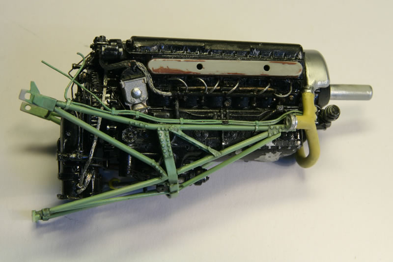
Engine Mount
The engine mount misses a couple of major struts in the center, both forward and back of the U-shaped support. Initially I found I couldn't put the forward struts in because of the oil tank. In the end I found that the oil tank is completely wrong (for more, see below) so that wasn't a problem at all. The back struts I put in while keeping the engine mount against the firewall in its proper position to make sure everything fits. The diagonal support struts at the front I originally misinterpreted as rods but I finally noticed in one picture (somewhere along the line of "now what on Earth are those funny plates with the holes in them?") that these are metal plates with holes so I removed the rods I had put in again and replaced them by metal plates with holes. The holes were drilled, not punched. I tried punching for at least five attempts and never managed to get the holes aligned and well-spaced.
Oil Tank
I messed about for a long time with the oil tank. First of all I determined that it would be sitting in the wrong place if you use the support on the tank in the kit and put that in the slot at the bottom of the engine. I filled up the slot and made the support longer but still had problems. A more detailed investigation of reference material showed what the problem was – the tank is completely wrong! If anything it resembles the oil tank of a Mark IX. On earlier Marks the oil tank is different. There the bottom of the oil tank is actually the outer skin of the fuselage (clearly marked on the outside of the kit as well), so the oil tank isn't a separate item sitting inside the engine compartment. I threw out the kit's oil tank and scratchbuilt a new one inside the lower part of the fuselage.
At first I built it in one half of the fuselage, meant to be slotted into the other half once the fuselage was assembled. I came to realize, however, that there would be no way to smooth over the groove at the seam on the inside between the two halves of the fuselage bottom once the engine would be in place, so I cut off the part from the left-hand fuselage and glued it to the right-hand side. I filled in the groove and sanded it all down on the inside and outside. Photo 5 shows the oil tank during construction.
Engine Top
The engine top was all wrong. I don't know where Trumpeter got the reference for what they did but it doesn’t look like any Merlin I have seen. The head covers are too wide and thick, but that is easily corrected. Placed on the guiding pins on the kit engine the covers are too close together, the result of the cylinder V-angle being way off. The distance between the covers should be 13 mm, (or maybe even a bit more), as given it is 9 mm and you can get to 10 mm by sanding away the sides. The best you can get on the kit without messing with the shape underneath the covers is 12 mm, so I decided to remove the guiding pins and move the covers outwards. The covers also miss the Rolls-Royce lettering (at the very least there should be a flat panel where the letters once would have been). The number of bolts on the side of the covers is incorrect so I removed what was there and replaced them with styrene rod.
The ignition harness on top consists of a pipe with wires coming out as 2-4-4-2 in sequence, with the wires going to the center line of the engine, and not as in the kit a centered pipe with a total of six wires coming out in pairs to either side which then appear to connect to the bolts that keep the cylinder heads in place – of which there are far too few in the kit (six on each side, while there are two for each cylinder plus a few additional at front and back). The kit engine has some rather nice detail, looking like two circular plates stacked and then two pins coming out of that. Just a pity that these are too large and need to go much more to the center.
So I cut the detail off the top, put in 0.7 mm styrene rods for the many bolts on the side, use a grinding tool to cut out the deep trenches where the ignition wiring goes in, put new circular plates in their proper position, connected by the piping, and made a new ignition harness. The ignition harness (on the sides as well) is made of styrene rod, painted black, with small holes drilled only partway through where the wires go in. The ends of the rods are covered with styrene disks, either simply flat (the termination) or with a center hole drilled where the braided wire from the magnetos goes in.
Magnetos
The magnetos from the kit don't look half bad but they are a bit too thin so once again I scratchbuilt them. The actual back of the engine (behind the cylinders but in front of the supercharger) is not accurate, but I left it as is. The connecting rods coming from the lay shaft on the back of the engine I put on later as they are very fragile.
Generator
I considered the part of the generator that is on the kit's engine to be good enough but it misses its whole front end so I scratchbuilt that from sprue. The inlet pipe is sprue heated (in boiling water), bent into shape and its center drilled out.
Compressor
The compressor with its cooling ribs presented me with a lot of headaches. First I fiddled around with styrene disks but they are too thick. Then I punched disks from sheet metal which is “okayish” (at least you get close to the required number of ribs for the height). The problem then was gluing these disks (alternating wide and narrow) into a stack. I must have tried five times or so but each time the stack ended up crooked (the superglue between the disks did not flatten out well enough). In the end I made a guide from styrene, three prongs sticking up from a base plate in such a way that the larger disks just fit inside. That went reasonably well except that the thing broke apart when I removed it from between the guides. So it still took two tries and even then the second needed repairing once more.
The compressor is too fragile to put on until the very end.
More on the Engine
There is a support bar underneath the top cowling over the centerline of the engine. On the kit this support is too wide to be usable. It is difficult to scratchbuild since it has lots of rivets. Since in reality it is removable anyway I left it off. I also removed the curved supports coming up from the side towards the back. The ones up front I left in place. I did remove a centerline support from the kit that runs over the coolant header tank as that doesn’t exist in reality.
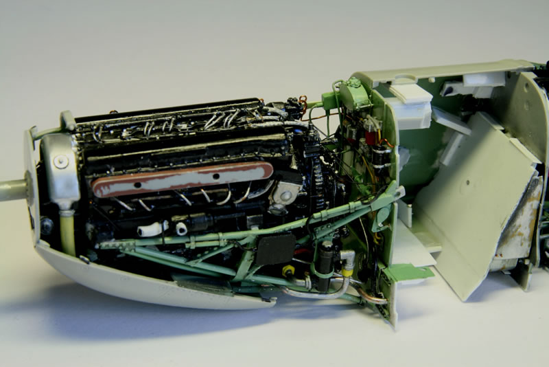
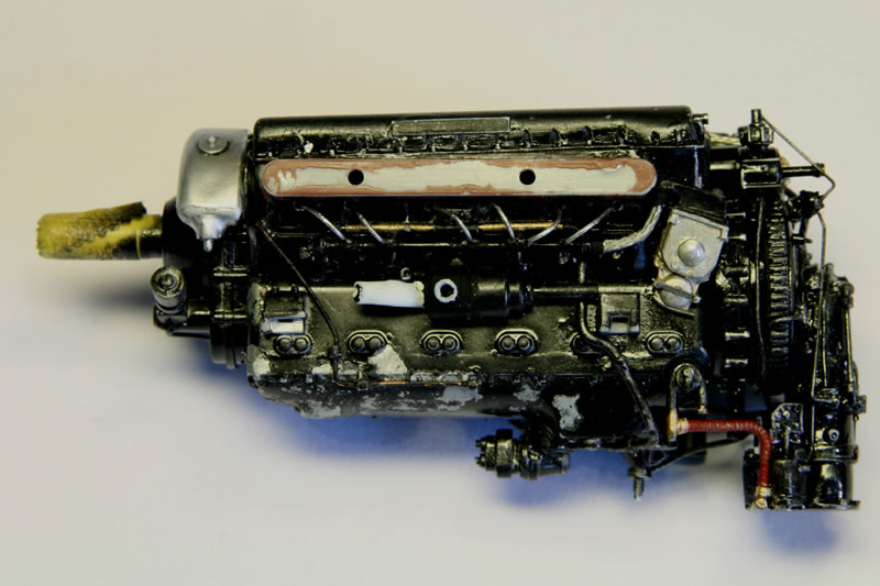
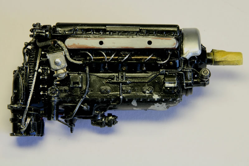
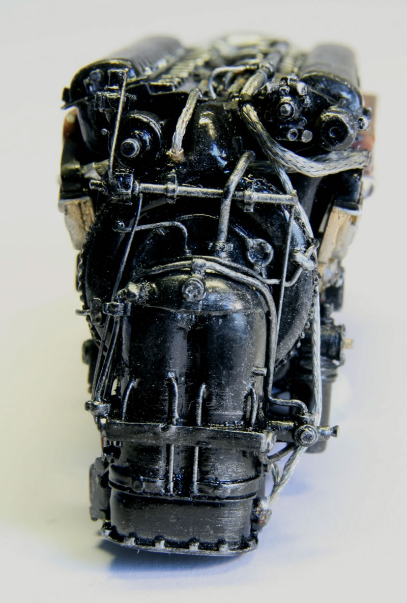
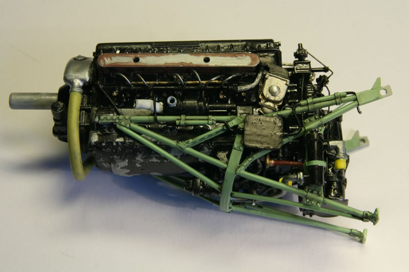
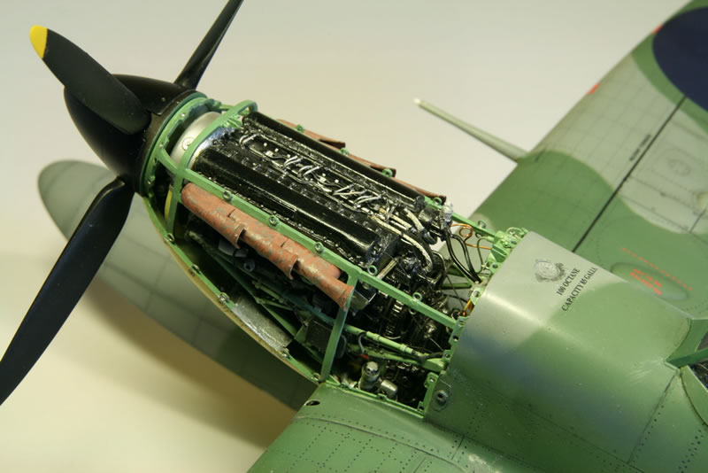
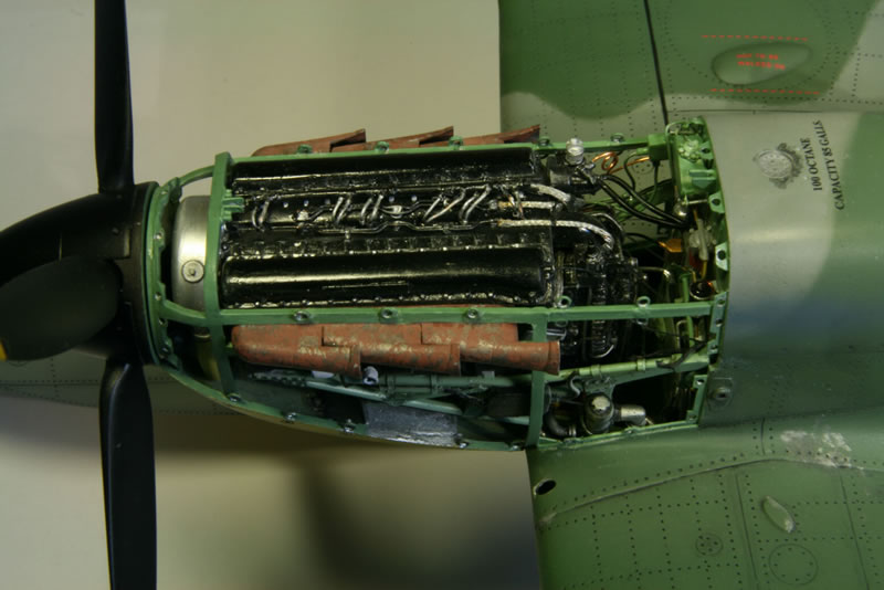
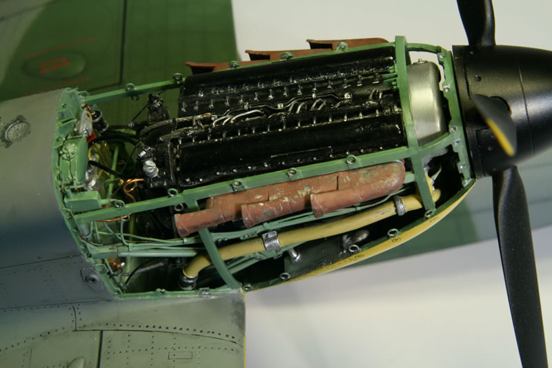
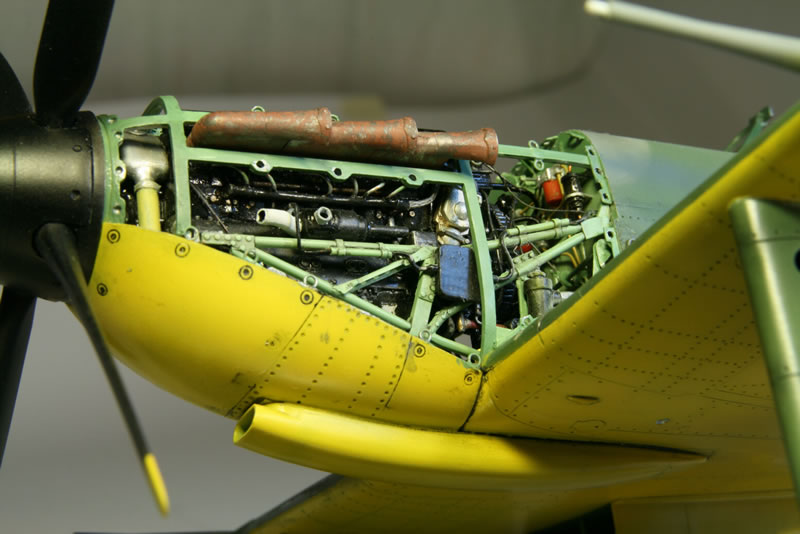
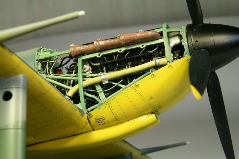
Photos 6 through 11 show the engine, the 6, 7 and 8 separate, 9 and 10 mounted in its frame and 11 mounted on the firewall.
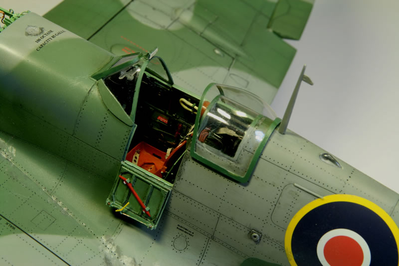
Cockpit
At first glance the cockpit doesn’t look too bad. Until you consider the floor which is totally wrong. The floor of the Spitfire cockpit is actually the bottom of the fuselage. The fuselage is a self-contained unit that continues between the wings. The latter are attached to the center section of the fuselage and then wing fillets create the flaring appearance of the fuselage to the wing. These fillets are hollow. Most models do not do a good job at reproducing this. Instead they simply use the top of the bottom wing or some spurious “floor”. And then the bottom cockpit side follows the flare of the fillets outwards instead of bending inwards. The floatplane does have one of these spurious floors.
The inside of the fuselage further back also is poor. It doesn’t even remotely resemble the real thing and if you want to do a decent job you have to remove it. For the most part I scratchbuilt the inside. One of the problems you always have with kits is the thickness of the fuselage wall which is much more than in the real thing. This makes it hard to get the dimensions right. I did my best but still there are some problems. The seat frame barely fits in its place while in the real thing there is ample space. And the protective covers near the pilot’s feet stick out too far to the inside, giving fit problems with the bottom of Frame 8 (instrument panel).
Fuselage Frames
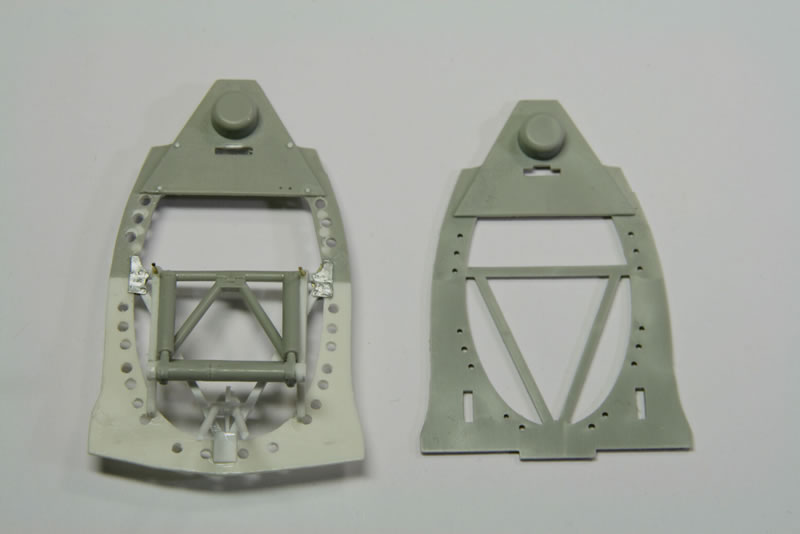
Because I still have an unbuilt Trumpeter Mark VI kit which has a lot of identical parts, I can easily show a comparison between the original frames and what I made of it. The numbering used is the official Spitfire construction numbering.
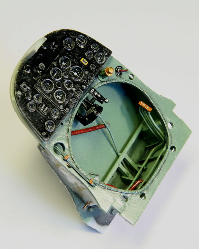
Frame 8
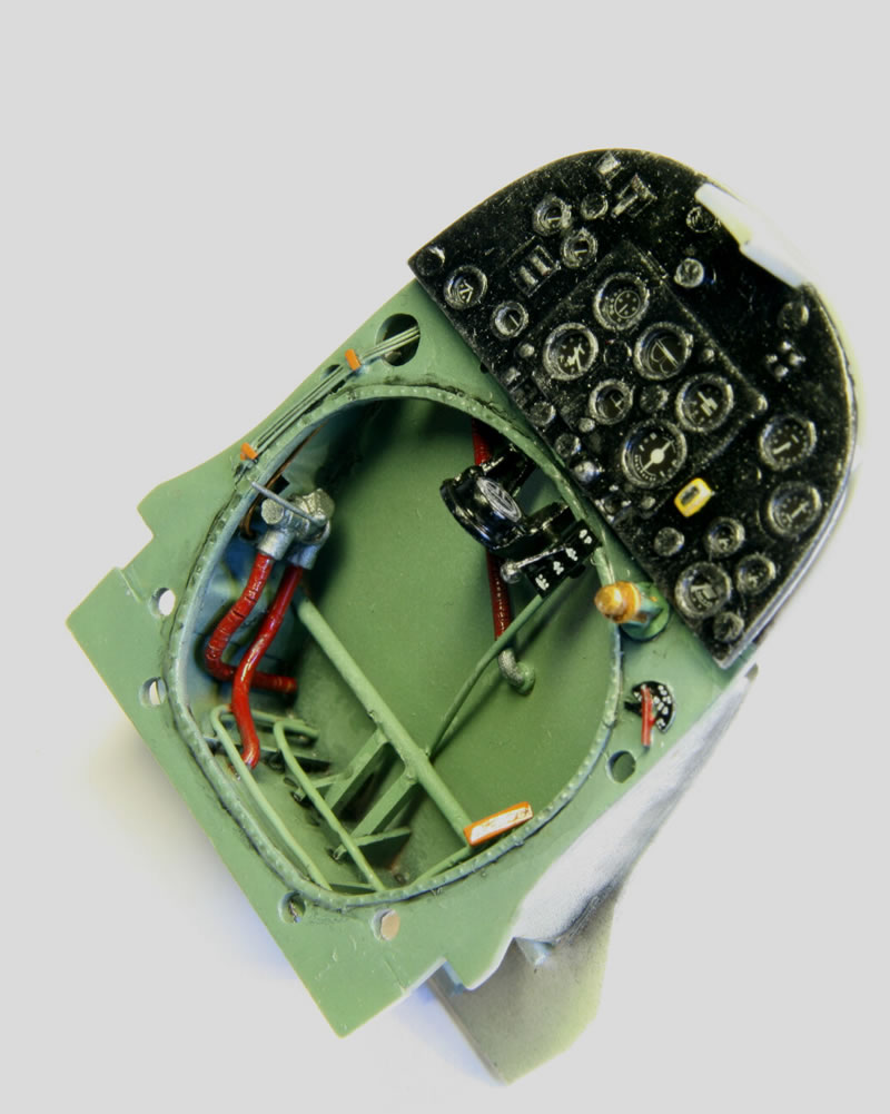
Frame 8 is behind the instrument panel (photo 12 shows the original and the result after modification; note that the styrene strips behind the instrument panel were removed later as they make the panel come too far forward). The hole below was way too narrow – the foot pedals didn’t fit. Holes were in the wrong place, the rivets were too few and way too large. The new rivets are decals (Archer Fine Transfers). Additional details are the back of the Ki-gas priming pump (the rest of the pump is not yet on) and fuel gauge selector (right). The compass is positioned (correctly) off-center to leave room for the scratchbuilt fuel on/off lever.
In front of frame 8 (or behind the panel as shown here) is the firewall between the cockpit and the lower fuel tank. That was all scratchbuilt.
I tried to make clear fronts for the instrument panel dials by punching disks from clear plastic sheet. However, because the instrument sheet itself is a bit far from the front (despite the fact that I backthinned it a lot) the “glass” fronts tended to obscure the details of the instruments too much so I removed them again (I had not glued them in, they stuck in place because they fitted just right.)
I scratchbuilt (from left to right next to the compass), the main fuel cock control, the fuel priming pump, and fuel gauge selector. The fuel lines were made from lead wire. The real things have a spiral reinforcement which I approximated by rolling the wire underneath a sharp knife at regular intervals, creating circular grooves.
The combined frame 8, instrument panel and structure in front of frame 8 is shown in photos 13 and 14. The structure forward consists of the firewall between the pilot’s feet and the lower fuel tank, fuel lines and drop-tank control (port side) and hydraulic lines from the undercarriage control.
Frames 9 Through 12
Frames 9 and 10 are incomplete frames that are not included in the kit. Frame 10 is mostly underneath the seat, while frame 9 is a complex structure that holds the support structure for the control column, the rudder pedal rods and the drop-tank control (far right). Photo 15 shows the – largely scratchbuilt – frame.
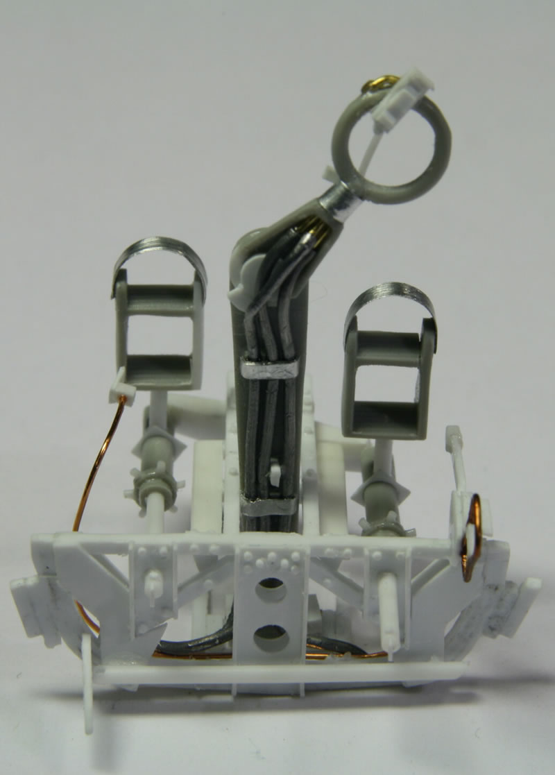
The control column is mostly the original thing though the top was removed and put at an angle (so the ailerons could be put an angle as well). The end result turned out a bit too large once it was mounted so somewhere along the line I must have goofed (there are lots of detailed pictures in the reference books but what is lacking is an absolute scale; though later on I found a remark from somebody else on the Internet that it is a kit error). By then it was too late though. The column is far forward so the elevators need to be fully down.
The detail on the control column that was scratchbuilt includes the gun button (the one in the kit is for machine guns only and lacks the cannon-firing control), the brake lever at the back and various air pressure lines. The latter are lead wire.
The foot pedals were too wide so a cut was made on one side and the width reduced. The tops are way to thick and replaced with sheet metal bands. The pedals are mounted with the right-hand one fully forward and the rudder turned accordingly.
The rest of frame 9 is mostly scratchbuilt. On the right-hand side is the control for the drop tank which would have been present on any Mark V (on which the floatplane is based).
The radiator flap control from the kit was used, but bent about 1/3 up from the bottom. It was mounted at the bottom in a scratchbuilt ratchet control and tilted all the way back, which means that the radiator flap must be mounted fully open. Photo 16 shows the results as mounted on the right-hand fuselage half but the with seat not yet in place.
Frame 10 is rather simple and was made from sheet styrene. Frame 11 is the seat support frame, shown in comparison in photo 17. Frame 12 is located behind the cockpit. Photo 18 shows it in comparison again. It has a fuselage floor from sheet metal, not the best choice for material as this turned out to be quite difficult to modify and the styrene ribbing doesn’t adhere very well. Behind the horizontal bar with holes is the antenna support structure (a horizontal cross with the base of the antenna – which sticks well into the fuselage – at the center of the cross).
Frame 13 is the hindmost detail built into the fuselage (photo 19), again with a floor. The horizontal bar is part of the R/T transmitter support. Behind frame 13 the fuselage was painted flat black so nothing is visible.
Cockpit Modifications/Scratchbuilding
In general I tried to put things where they ought to be as faithfully as I could, but things tend to wander around a bit between Spitfire Marks so it is not always easy establish what should be where.
Starboard Side
The undercarriage control section of the kit is reasonably OK but needs to be deepened by adding sheet styrene to the back. The hydraulic lines needed to be made. There is a small wheel with holes at the top where the control section goes against frame 8. The construction that fixes the control to the cockpit sidewall (plates and bolts/nuts) was also made. The other two controls provided in the kit, the remote contactor and the signaling switchboard are fine except for the cabling. The signaling switchboard lacks a Morse key. I made one but it kept on breaking off so I gave up on it. I added a cockpit light, spare gun sight bulbs (made from clear plastic sprue) and an instruction sheet next to the signaling switchboard. There are some electrical controls to the right of the seat frame.
The IFF destruction buttons were wrong so I scratchbuilt them, including the two large switches to the right. The windscreen de-icing tank could do with a bit more detail like the bolts on the circular front panel (made from Archer Fine Transfers) plus the details on top, the tubing, the selector and pumping lever. The oxygen control valve and tubing and oxygen hose were added.
The cover plate at bottom left (underneath the undercarriage hydraulic lines) is really hollow so it was filled with sheet styrene at the back and then the side was opened up with a rotary tool (the same on the port side).
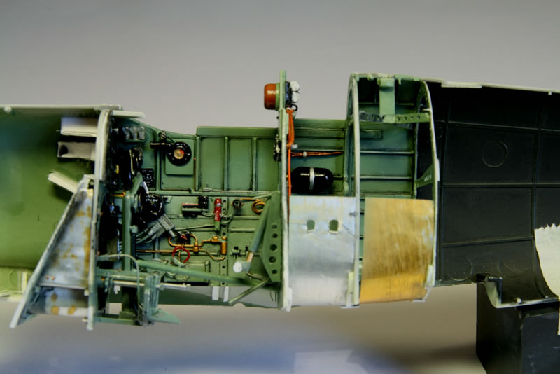
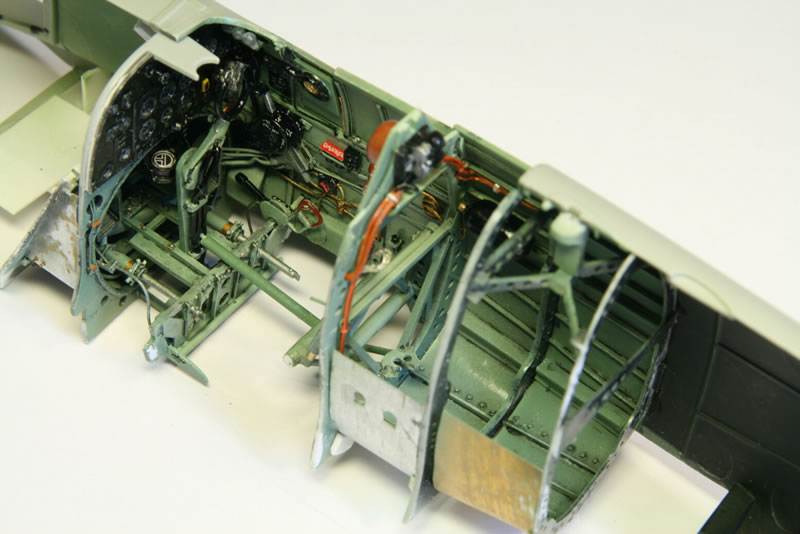
Photo 20 shows the right-hand side of the cockpit, plus what is behind it (if not masked by the left-hand side of the floor coming up). Towards the extreme right is the cross-frame supporting the antenna mast base. Inside the antenna I drilled a hole and fitted a metal rod in there. The rod fits into a hole in the mast base, giving a stiff support that should make the mast less prone to misalignment (or breakage).
Port Side
The throttle quadrant is fine except for control wires. The trim controls unfortunately are not. They are nicely shaped but too large (by about 10%). I found them too difficult to scratchbuild so I kept them.
I left off part H36. It is seen in some cockpit pictures of other Marks but I have no clue what it is supposed to be for. The Spitfire floatplane would have had a tropical air filter installed so the manual air intake control needs to be built for the port side of the cockpit. The map case was too large and lacked a top. The radio plug stowage bin (frankly I haven’t got a clue what that means) next to it was made from sheet metal. Once more I added a cockpit light and cabling for the gun camera control.
Photo 21 shows the left-hand side of the cockpit. The lower sidewall is not yet glued in place because then it could not be mounted properly with the wiring going forward through frame 8. Instead it was held in place when the fuselage was closed, making sure the wires go through their holes. Only then was it glued onto the left-hand fuselage part.
Seat
The seat is another part of the kit that makes one wonder. Instead of the standard Spitfire “bucket” seat it has a flat “wood” base. It looks like they worked from a picture in Ref. 5 where somebody put wooden slats across the bucket seat (to seat a dummy dressed up as a pilot). Initially I thought that Trumpeter must have some information about the floatplane that I was lacking, to create a seat like that. Until I found that the Mark VI kit has the same seat! So I concluded that the seat is rubbish. I created a proper seat from sheet styrene. After it was all finished (photo 22) I found that Grey Matter Figures makes a 1/24 replacement seat as well as other parts…
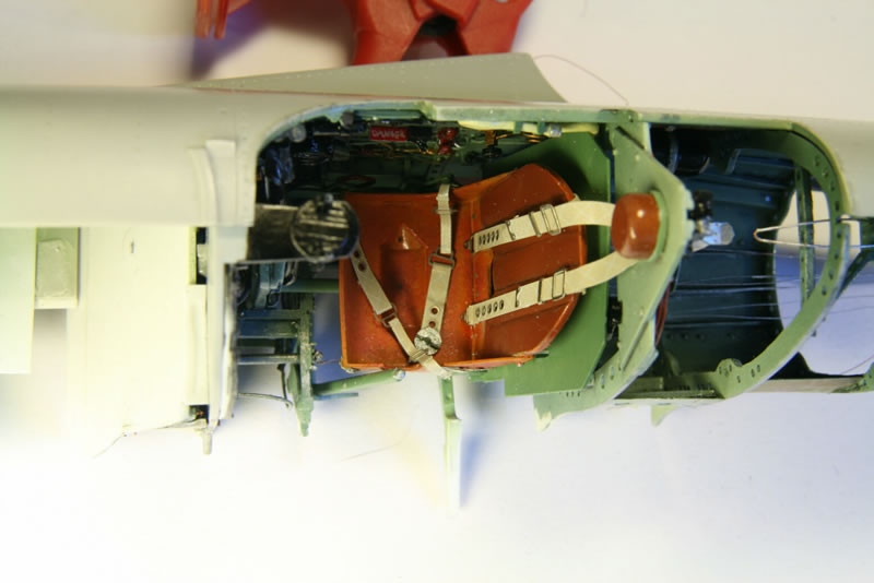
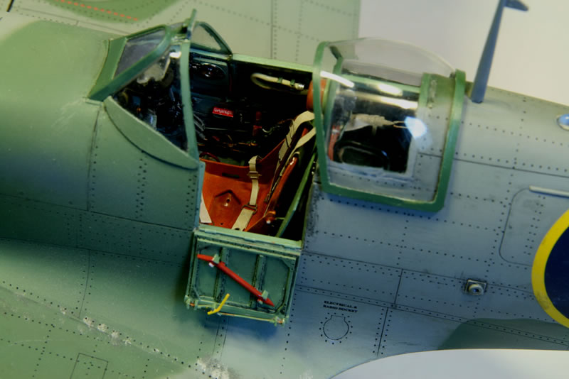
I had a hard time figuring out what the seatbelts look like (photo 23). For one thing, the reference material is decidedly sparse on this. Photographs with original seatbelts mostly have the belts removed from sight. So I was very happy when I found out that Eduard makes 1/24 scale seatbelts and I ordered two sets (the other for the Spitfire VI). It turned out that I already had one set in stock (that apparently I had bought much earlier but forgotten about). The Eduard seatbelts still have some problems though (their 1/48 fighter seat belts actually look better). The harness going back through the armor plate has a V-angle that is too wide (the canvas strips should be almost parallel coming off the back plate). To get them through the armor plate you have to bend them towards each other which buckles them. Fortunately that is out of sight underneath the voltage regulator at the back of the head rest. Especially so since the part going back is too short. A bigger problem is that the fastening makes no sense. The canvas belts seem to end in nothing and there is some obscure contraption on one side. I couldn’t figure out what that was supposed to be so I removed it. One reference photograph shows that the lower belt coming from the right has a circular buckle into which the other belts click. The ends of the other belts are then best supplied with part 4 (with the “ring” cut in half). Since there are only two of those (and I lost another one), I plundered the third set of seatbelts for those parts. The buckle I made from sheet styrene.
Behind the Cockpit
The oxygen bottle on the starboard side was mostly kept as is except for tubing added. The voltage regular at the back of the headrest was scratchbuilt as was the cabling there. Barely visible on the front side of the head armor is the claxon, probably the most hated part of any Spitfire. It warned the pilot below a set speed that the undercarriage was still up.
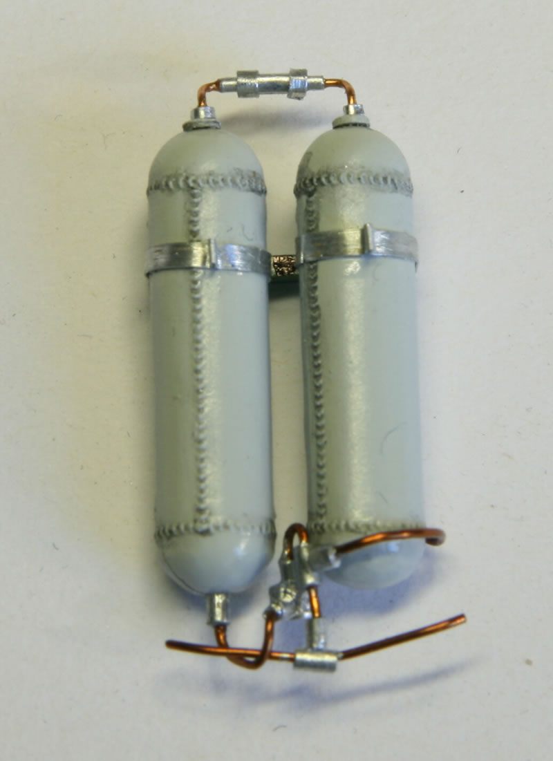
The pressured air bottles on the port side (photo 25) were scratchbuilt as the originals are too small. The mounting frame is wrong (the bottles need to be further up than the kit suggests). Weld seams were made from Archer Fine Transfers. Tubing was scratchbuilt. The bottles were a bit problematic because they are mounted on the port fuselage half but that could only be done once the floor in the other half was in place, which means after the fuselage halves have been joined. The tubing is simplified, partly because it is barely visible, but also because it isn’t clear from the reference photographs what exactly is there.
Lettering
There are no decals provided for the cockpit interior nor was I able to find any. The major problem with making them yourself is that the far majority is white lettering on a (mostly) black background so you cannot print that with an ink jet printer. I did my best, since not doing anything makes for a rather monotonous interior. I quickly found out that with paint and paintbrush it was impossible to create fine detail. In the end what I used is a drawing pen (I still have a lot of these, from the Stone Age before computer graphics were around). Normally you’d use Indian ink, but I could not obtain white ink any more. So I used Model Color white acrylic paint which I diluted with water. The best I got is the “DANGER” sign on the red flap above the IFF destruct button. The rest of the lettering is more or less smudges of approximately the right size in the proper places.
Wings
I decided that I had spent too much time already on the engine and firewall so I wasn't going to expose the gun bays (there are more problems there). I glued the flaps and ailerons in position using the hinges supplied with the kit. Before I fixed upper and lower wings together I made sure the ailerons could be moved into their proper positions, -18° on the left side and +24° on the right side. And a good thing too that I checked, because there is no way the right aileron moves up more than about 10°. First of all there are ridges on the top of the ailerons which should not be there as the ailerons are roughly triangular in cross-section. I removed the ridges and as much of the right-hand upper wing on the inside as I dared but still the aileron would not move up far enough. In the end I broke the hinges free again, made the slit where they go in deeper so the hinges could go lower and put the aileron back in. That was the only way I could get the aileron to move up far enough. I then glued upper and lower wings together.
I had significant fit problems with the front part of the wings against the fuselage. I don’t think it was my fault (with the addition of the inside structure in the fuselage) but can’t be sure. I sanded away some of it until I had a reasonable fit, then glued the fuselage into place. I kept applying superglue to the gaps until as little as possible remains (the seam isn’t a panel line as elsewhere but the place where the fillets lie on top of the top of the wing). On the left-hand side I had to sand away at the front to make top (the fillet on the fuselage) and bottom (wing) fit together. On the other side I had to fill up the fillet side with a little strip of styrene, then sanded that to conform to the curve and smoothed with superglue.
The oil cooler radiator doesn’t have the right kind of detail (a fine hexagonal mesh) so the front and back end are best kept dark to hide it. It is impossible to scratchbuild that kind of detail. The other radiator is reasonable though much too low. The real radiator sticks far into the wing. I painted both sides titan (Model Master) metalizer (the darkest I have), then highlighted the ridges with aluminum dry-brushing.
There are two pipes in the kit that are to be mounted aft of the radiator. They would be for the gun heating system, but the only reference that I found is for a Spitfire I. Since the gun heating system of the Spitfire V differs (the vents near the wing tip on the bottom need to be removed and the resulting holes plugged) I decided to leave the pipes off. If they were there in reality, they would have been above the lower surface of the wing anyway. The small pipe in front is correct (it is variously identified as a fuel-system vent or a de-icing spray tube; I don’t know but venting fuel into a hot radiator doesn’t sound like a very bright idea).
Tail Section
Trumpeter did something weird with the upper surface of the horizontal stabilizers. Unlike the undersurface which is normal and looks like metal plates riveted on, the upper surfaces look like they are supposed to be made of fabric (like the elevators). I sanded the upper surface smooth, scribed panel lines and drilled out the positions of the rivets. As a mask for the rivets I used scanned images of the undersurfaces, printed at the correct size and taped over the real parts. (But if you are planning to build one of the Trumpeter 1/24 Spitfires, do yourself a favour and buy the Grey Matter Figures parts instead. I already have them, as well as the seat, for my Mark VI.)
Control Surfaces
Trumpeter supplies hinges for the control surfaces made from photo-etch metal plus metal bars. At first sight that seems to be a nice touch because it allows you to change the angles of the control surfaces even when the kit is completed. Personally I do not like that very much because you then get a mismatch with the position of the control column and rudder pedals in the cockpit. And it is very difficult to keep a semblance of normality, with ailerons pointing correctly in opposite directions and both elevators at the same angle (especially if you have a son with a sense of humor who likes to mess them up).
I did use the hinges supplied but that turned out to be not so smart. For the ailerons and flaps the first problem is that the hinges supplied do not occur at the positions where the real hinges are. Especially on the ailerons you get a glaring mismatch because the panel lines there do point at the correct position. The second problem with all of the hinges is that if you use them and change the angle of the control surfaces, you cannot reproduce the positioning on the real thing. There are gaps on the elevators and rudder that do not occur for real. Besides, the real hinges, when visible, look completely different.
My advice is to chuck the hinges as supplied, if necessary modify the control surfaces so what hinge is displayed is correct, make sure the controls fit well in their angled position, and glue them in position. For me that was too late so I fixed the lot with superglue, then filled in the gaps where the hinges are with superglue and painted over them.
Reinforcements
I made a lot of reinforcements (following Ref. 11), especially behind the firewall and frame 8 with the instrument panel so they remained in place in only the starboard half of the fuselage. I also added reinforcement (1x1 mm styrene strip above and below the slits where the horizontal stabilizers go in) for the tail. The kit itself is rather skimpy there and it will not make a solid fit. With the reinforcements in place I did not have to worry that the stabilizers sag to the wrong angle once mounted onto the fuselage.
The pitot has a problem in that the hole where it goes in is slightly too large. I first drilled a hole partway along the length of the vertical part of the pitot. I added styrene bar, also with a hole drilled with wire inside, to the top, so now the vertical part of the pitot extends all the way to the top inside of the wing. Once it went into place, I could just use regular glue on the top to fix it properly in position against the bottom inside of the top wing.
Painting
I used mostly Humbrol enamels, with only the bottom yellow from Modelmaster, while the dark green possibly – see further below – was Revell. The painting was easier said than done. A try-out on an old surplus Spitfire wing showed that preshading is very effective in making color variations without having to worry too much about the exactness of where the preshading goes. I used my airbrush with its finest nozzle. Panel lines got more shading, rivet lines less. It is a laborious process. The fine nozzle got clogged frequently with the fine spraying and I had to clear that by opening up the paint flow (pointing somewhere else than the model). Typically the underside of each float took me an hour or so. The same for the tops. And the rest of the model even longer.
I did things in steps. First the float undersides, preshading, top coat (generally a well-diluted paint with at least 50% white spirit, otherwise the coat gets too thick very quickly and hides the preshading), and a cover of Future, all while the tops were masked off. Then the reverse, masking the bottom (taking care that only Tamiya masking tape is on the painted surfaces; other, cheaper painter’s tape, etc. can be put on the Tamiya tape but never directly on the paint as removing the masking is likely to damage the paint), preshading the top, roughly masking the green (leaving some gray overshoot), and applying the gray top coat, again thinned. I then masked the gray areas and applied the green top coat. The gray is used as is (except for thinner), the green was lightened up with white (about 10%).
The same procedure was repeated for the rest of the model. The bottom went OK. And then Murphy cut in. The gray top side was applied too thickly which only became apparent when it dried. The preshading was completely hidden. So I quickly removed the top coat with a rag with white spirit. That went well, the preshading was hardly damaged at all (I had left things to dry for several days). What I failed to notice is that I also applied a lot of fibers. They did not show up until I tried the gray again. And hurriedly had to remove that again as it was a big mess!
At that point I made a full stop. First of all, I thoroughly cleaned off all fibers I could find. I had already noticed that there always were fibers on the painted surfaces. I then took all the precautions I could to eliminate the problem:
- I already used to switch on the exhaust of my spraying booth a while before starting. But since the booth vents to outside the house, air is drawn in underneath the door of the room from the other parts of the house. And they tend to be dusty. So I put a large towel on the floor in front of the door and opened the window. With the rainy weather, the outside air should be reasonably clean.
- Remove my sweater (it tends to have an accumulation of cat hair, though I do not think the fibers are those) and put on an old shirt with the arms cut away.
- One weekend I even cleaned up the whole room – which turned out not to be all that dusty after all!
The amount of fibers has diminished but the problem is not gone totally. So now after a coat I painstakingly pick off what is there. What remains can be sanded off with extremely fine sanding paper after that.
The top coat of the fuselage and wings I also took in several steps, one wing or part of the fuselage at a time. The degree to which the preshading shines through the top coat varies, which is fine by me. It wouldn’t be uniform on the real thing anyway. I also kept it subtle. The floatplane in Egypt would not have been pristine on account of the effects of the salt water of the lake and the fierce sun, but neither would it have been all clapped out as some operational planes were.
The demarcation between gray and green is a bit more fuzzy than I would have liked. I mounted the paper shading (whose edges I coated in Future before to reduce fibers coming off) on little blocks of styrene with masking tape superglued to either side (so the sticky side of the masking tape points away from the block). This created spacers so the paper sits a little away from the surface, allowing a slightly fuzzy edge and preventing a ridge building up. The problem was that because you need to spray at various angles due to the shape of the model, you tend to spray underneath (and you actually spray between the gaps between the blocks). The solution would have been to bend down the paper after the initial spraying of the edges (see Ref. 12), but I didn’t use poster putty (the stuff you can buy here is more sticky and I don’t trust it to come off easily enough). I cleaned up with Q-tips slightly wetted with white spirit.
Two More Setbacks and a Near-Disaster
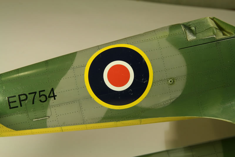
Once I felt I was ready, I started applying the decals. And I found out the hard way that I should have remembered what I had noticed early on: the fuselage roundel decals are correct in size, but the instructions are not! Not only do the instructions display the roundels much too large, they are also in the wrong position (too far forward). Unfortunately I used the instructions to create the masks for the camouflage colors. I did not want to paint on the green color on in the “default” pattern and then apply the decals on top of that, as I was afraid the decals would be slightly transparent and you might see the green-gray border through them. I need not have worried about that. But now I had a fuselage painted with areas where green should be and wasn’t – because I had assumed that that was where the decal would go (photo 26). I carefully tested frisket foil to see if I could use that to cover the decals so I could spray-paint the missing areas. The reason for the foil was that I could easily make circles by drawing lines with a compass and then cutting it. It seemed to work fine, it wasn’t really very sticky. The next day I painted – but used the wrong color so I had to remove that again. It seemed the removal had caused some paint to leak underneath the masking foil so I removed the masking again. And found that now the foil stuck much harder to the decals than before, drawing glue threads. In the end I managed to get it off by soaking the glue with white spirit but a few pieces of the decals had come loose and I very, very carefully had to “unglue” those from the foil and put them back in position again. I did it without too much damage being apparent but it was a close call.
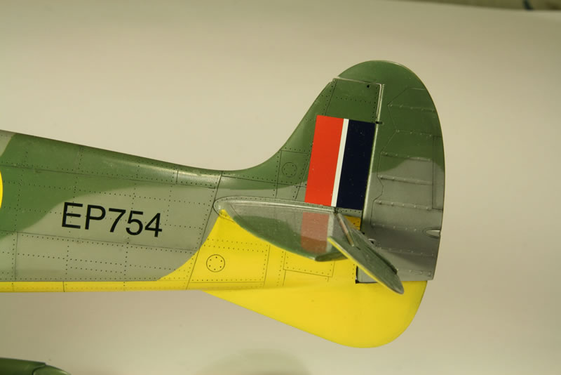
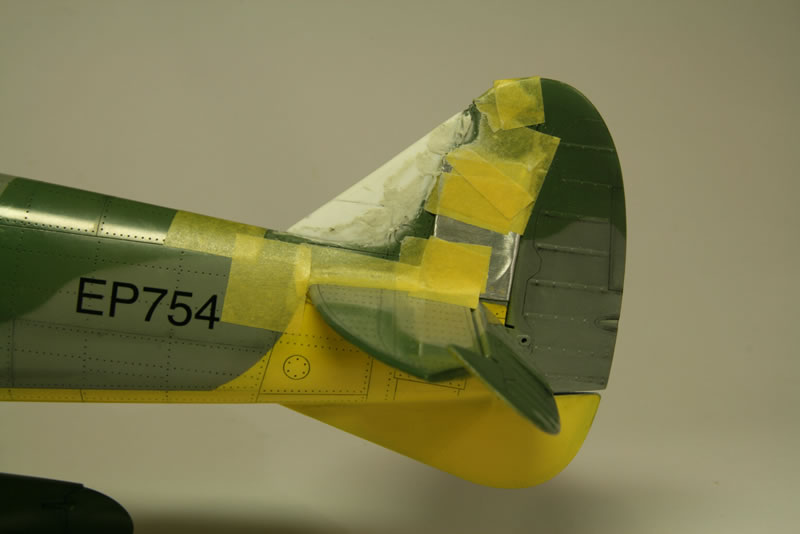
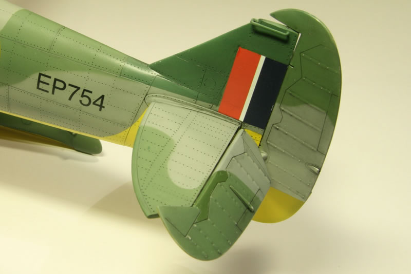
Somehow though I wasn’t able to match the exact color of the earlier paint work green (see further below). That was the first setback and the near-disaster. The next setback came when I applied the tail red-white-blue identification bands. I carefully looked at the reference photos and suddenly I was struck by something I had not noticed before. The leading edge of the fin is wrong! The kit has the normal Spitfire edge. Which is the early style edge for W3760, but all floatplanes (including the later Mark IX conversion) had straight leading edges with an enlarged fin area. Even W3760 had a straight edge, once it had been modified with for example the enlarged carburettor intake with the tropical filter – which is how the kit is. So the kit either has the wrong intake (too late to change that) or the wrong fin. I decided to see if I could modify the fin. Rather than hack my way right in, I took this in slow steps. I first made a new leading edge by building up from pieces of styrene sheet, layer by layer. I started with 1 mm for the center, made sure that fit. Next I glued 0.4 mm sheet on either side, modified the whole thing so it fit (and started tapering towards the top), etc. I repeated this until I had a piece that fit moderately well (the very thin transition to the real fin cannot be made this way). I did the panel lines, rivets, etc. Finally, once I was satisfied that it would work, I removed the paint from the old leading edge and put the new edge in place. I made sure I had a good transition using superglue (I found out that putty doesn’t work for this), then sanded it all in shape – taking extreme care not to damage the fin decals which were already in place then.
In all it worked reasonably well (photos 27 through 29). There is some damage to the decals. If these has not been in place already, the easier procedure would have been to cut off the leading edge at the pronounced sloping panel line halfway (but that cuts through the decal).
A further note on masking tape and decals. I did some damage to existing decals when removing masking tape. I think the best way is to use a paintbrush soaked in white spirit and to apply the white spirit to the edge while gently pulling away the masking tape. The white spirit dissolves the glue quite well.
Finally things were coming together. Except for some fine detail it was finished. The decals were in place. The model was given a last coat of Satin Cote, with some areas (floats and parts of the wings and top of the fuselage) with Matt Cote. The latter is to resemble weathering of the paint in areas exposed to sun (top) or the water (floats). Light exhaust stain was simulated with matt RAF Blue on the fuselage behind the exhausts ad well as on the cowlings near the exhausts. I didn’t put on any gun smoke stains as I figured the guns would not have been used much.
Next it was time to remove the masking material from the engine and cockpit and assess the damage done – which turned out to be remarkably little. In the engine area the exhausts had to be put on. The exhausts had been painted earlier with a rusty dark color with lots of patches of different metallizer (ModelMaster, various shades). Also the support structure for the cowlings had to be made/fixed up. I needed to make additional rings as I had already lost a number of them. The rings were made by rolling copper wire into a spiral around a drill (1.2 mm), then cutting through the spiral along its length with strong and very sharp scissors. The resulting more or less round pieces were then flattened (in the plane of the ring) and bent back so the ends at either side of the cut touches. The real things are somewhat elongated and not truly circular but in the absence of a suitable former I stuck to circles. The rings are along the bottom of the side cowlings and on all cowlings towards the back. Near the firewall the fasteners go into scalloped plates which I made from thin sheet styrene. Somewhere along the line an error crept in. The plate along the top back had to be cut into separate pieces otherwise it was too far forward over the hydraulic tank (it looks rather weird, a hydraulic tank where you cannot remove the cap since the fastener plate is in the way).
The fastener points on the fuselage were given an inside paint job with aluminium. On the real thing the fasteners have the normal inside (green) paint color, but of course the paint on the inside of the holes is damaged by the fasteners.
The Cowlings
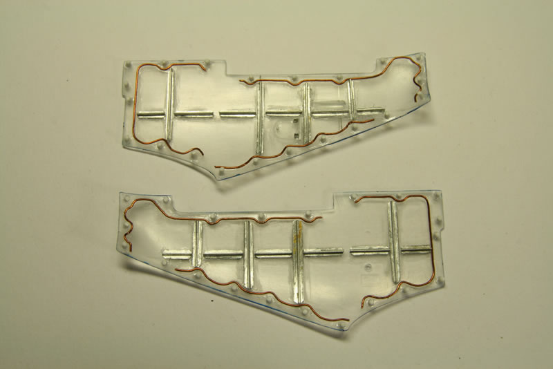
The side cowlings were a disappointment. I wanted to display the inner surfaces of these (the internal structure of these panels is well documented). Unfortunately Trumpeter made the side cowlings from transparent plastic (it took some time for me to find them among the kit parts) which is far too brittle to work with. The Trumpeter Spitfire VI suffers from the same problem, so I could not use the side cowlings from that one either. Personally I cannot imagine anyone using those transparent panels – if you want to expose the engine, leave the panels off since their "transparency" is mostly in name: they are too thick to give a decent view of the inside.
I thinned the edges of the parts as far down as I dared – which isn’t all that much because of the brittle plastic. The inside structure (photo 30) was taken from Ref. 2 which is a Spitfire V. The other reference pictures from later Marks show a different layout of the inside strengthening, but I assumed the reference is correct for a V.
The decal on the right-hand side cowling has a pale gray background which isn’t the same as the gray I used. It would have been better if it had been given a clear background.
I later found out that there is an error in the fasteners and thus on the outside and inside of the side cowlings – there is no fastener above the oil tank so the row of fasteners at the bottom should show a gap. The corresponding fastening ring on the oil tank is easily left off, but I considered it to be too late for the cowlings, so I left them as they are.
A note on the fasteners at the back of the top cowling: It looks as though there was some change in the number and position of these for the different Spitfire Marks. It is a bit difficult to be certain, because there are not many photographs where this can be seen clearly. As far as I can tell early Spitfires have four or five, the only reference material (Ref. 2) I have on a V has six, while later Spitfires have more.
Cockpit Door
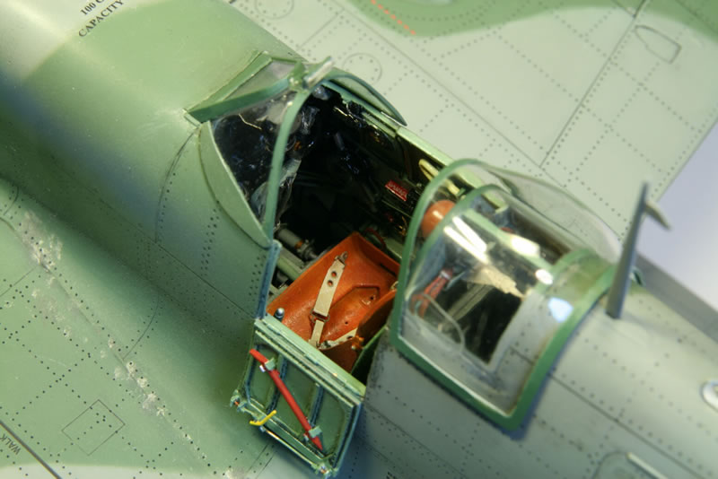
I did not like the crowbar and locking mechanism on the cockpit door as provided. The structures are molded against the door itself. So I scratchbuild replacements from styrene and metal wire (photo 31). I would have used the decals provided but they do not fit inside the recessed areas of the door. No real problem leaving them off since there is a great deal of variation, many planes having nothing. I also made a hinge from copper wire and sheet metal. I did not glue the door into place until the very last moment. One reason is that you need it to make sure the front canopy is in the right position by putting on the hood. Which you can only do with the door closed (it doesn’t close properly at the bottom because of the hinge, but for the hood fitting that doesn’t matter).
Canopy
After cleaning up and polishing the four canopy parts, I coated them with Future. I used it diluted with 50% alcohol because I found the Future as is too thick: air bubbles remained stuck to the canopy surfaces and ridges were smoothed over. Maybe it would have turned all right after it all drained off, but I was happier to use a thinner fluid. The canopies were masked off with bare metal foil on the outside, cut into the required shape, with masking tape on the inside. I left the masking tape sticking out, with another piece on the gluey side (so the glue is no longer as exposed) as that gives me a bit of a handle to grab the pieces. Painting was done by airbrushing inside color first, then outside color over that.
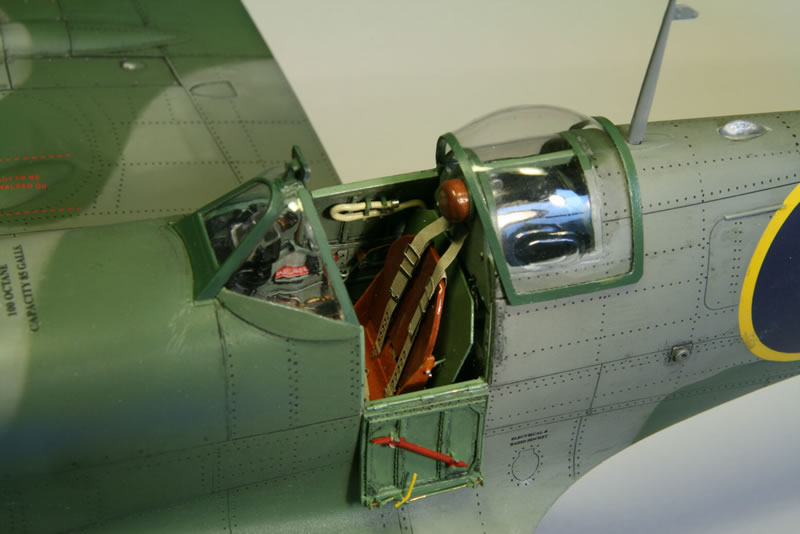
The hood is too wide for the fuselage and will not stay in position so I created runners from 0.5 mm styrene rod and glued them on the inside. The runners slot into the grooves and keep the hood in position without requiring filler or glue. The hindmost canopy did not fit over the headrest/armor plate so I had to sand that down a bit. The canopy also isn’t wide enough and on the left-hand side (near the door) sticks out. I left the problem above the door as is (it is masked a bit by the hood). The width problem I solved by first gluing the right-hand side and once that was dry I slightly bent the canopy and glued the left-hand side, keeping it in its proper position.
Before I put the front canopy in place I had to finish the gun sight. The reflector doesn’t fit. It needs to be at an angle of 45° but if you put it up that way, it doesn’t reach the supports. Since it is slightly too long anyway, I sanded off a bit from the bottom part until it fit well. The bottom rim also needs to be at an angle (it goes horizontal) so that helped with the final fit. For the upward-facing lens I punched a 3 mm disk of transparent plastic (from the lid of some kind of container), painted the underside aluminium and glued it between the reflector supports. I then applied several drops of Future (allowing it to dry in between) until it had a clear, convex surface. I also dipped the gun sight reflector in Future before I superglued it into position.
There is one major problem with the front canopy as provided. The side panels next to the windscreen are wrong. The real ones are flat, not curved, and the metal frame at the bottom curves up. I wasn’t prepared to cut off the side panels and replace them with something scratchbuilt, partly because the canopy is really nice and thin, but also very fragile. So I just made a metal frame curving up for the bottom. There are also metal plates below the sides that needed to be made (I thought, see below). Because the metal plates against the canopy create a lot of inner surface that is well visible when looking into the cockpit, I painted the insides as well (by hand).
Disaster Strikes…
After I had put the front canopy in place, I glued the additional plate on the port side on with superglue. I then continued with the starboard side one … and came to the conclusion that they were too large. The starboard one overlapped with the air inlet panel. I decided to leave them off. Fortunately the starboard one wasn’t in place yet. I carefully removed the port side plate again, using superglue remover to help. All seemed to go well, the plate came off. And then the paint started peeling. As quickly as I could I removed the remaining superglue remover but the damage was done. That on the canopy bottom plate isn’t the problem. But the damaged paint on the fuselage itself is. Now I really had to try and match the color as well as I can by mixing paints.
My first attempt – hoping that the color difference was the result of the coating with Future and Matt Cote – was a failure. The panel stood out like a sore thumb. So I removed it all again, first the Matt Cote with white spirit, then the Future will alcohol, which also removed a lot of the (wrong) paint. I cleaned up and redid the panel lines. I then went through all the Humbrol greens I had, mixing in a little white, putting a bit on a piece of paper and comparing it with the kit. Nothing matched! In desperation I then turned to the remainder of my collection of paints and finally, in Revell 363, I got something that actually matched quite well. Incidentally it is labeled as “dark green”. So now I am wondering whether it was the color I used all along, possibly because it is a satin-matt rather than a matt, and I generally prefer satin coats over matt ones. I first sprayed the gray undercoat again, but with a fuzzy demarcation rather than masking at the panel edges. After that came the green and the other coats (Future, black wash, Matt Cote). And it worked!
Gun Patches
The decals supplied for the machine gun patches are useless as they already have holes. If needed, I am quite capable to punch the necessary holes myself! I need patches without a hole. My first attempt consisted of Tamiya masking tape, taped to a piece of plastic and painted. One advantage of this approach would be that it can easily be removed again. But when I cut the tape into the square patches, the paint did not hold. After that I tried several other things like thin aluminum foil and painting some scrap decals, all without too much success. And then I found I was being silly. The decals of the kit do have fin flashes that are not used. And they contain reddish bands that are large enough to cut patches from. I put the resulting patches on the model. After drying I coated them with Satin Cote (it’s OK to spill a bit along the sides, the real patches were glued on and there often is a shimmering rim of glue visible).
Final Assembly
The final steps consisted of gluing the cockpit door, the pitot and the radio aerial mast. With regard to the latter I deliberated for a long time whether I would put a wire from the aerial mast to the tail. The biggest problem here is that from photographs it is almost always impossible to see if there is a wire there or not. Early marks like the I (Roman numeral one) definitely had a wire, but later marks did not. As far as I can guess it depended on the type of R/T transmitter. Some reference drawings (note, drawings, not actual photographs; Ref. 2) show wires on all Spitfire Vs, while another (Ref. 8) is much more discriminating and there the floatplane does not have a wire (none of the tropical Spitfires has one, while a non-tropical V does). Additionally, when a wire is present, there tends to be a kind of clip on top of the rudder to which the wire is attached. None of the floatplane (Mark V) pictures shows such a clip. So I decided against a wire. That also makes it possible to simply push the mast in place and not gluing it in, so it can be removed easily (e.g. for transportation).
The propeller somehow goes on only one way. In one orientation a gap exists between the spinner backplate and the front plate on the engine, when rotated 180° it is fine. Apparently these are not truly perpendicular to the propeller axis, but as long you put the propeller in the right orientation the problem doesn’t show.
References
- R. Cross, G. Scarborough (1971) Spitfire. Classic Aircraft No. 1. Their history and how to model them. Patrick Stephens Ltd., UK.
- R. Rimell (1985) Spitfire. Supermarine Spitfire Mk V. Aeroguide Classics 1. Aeolus Publishing Ltd., USA
- R. Humphreys (2000) The Supermarine Spitfire. Part 1: Merlin Powered. A comprehensive guide for the modeller. SAM Publications, UK
- F. Koran, V. Danda, J. Martinek, M. Khol (2002) Spitfire LF. Mk. IX. Wings & Wheels Publications, Czechia
- Aero Detail 8 Vickers-Supermarine Spitfire Mk. I~V. Aero Detail 8. Art Box Co. Ltd., Japan
- Aero Detail 27 Production Team (2000) Vickers-Supermarine Spitfire Mk. VI~XVI. Aero Detail 27. Art Box Co. Ltd., Japan
- A. Price, P. Blackah (2007) Supermarine Spitfire Owners’ Workshop Manual. Haynes Publishing, UK
- P.H. Monforton (2007) Spitfie Mk. IX & XVI Engineered (to a large extent the ultimate reference though details on fuselage frames behind the seat and engine are sadly lacking)
- B. Robertson, G. Scarborough (1974) Hawker Hurricane. Classic Aircraft No. 4. Their history and how to model them. Patrick Stephens Ltd., UK (excellent detailed drawing of engine with explanation)
- Aero Detail 23 Production Team (1999) De Havilland Mosquito. Aero Detail 23. Art Box Co. Ltd., Japan (excellent detail on engine photographs)
- J. Ferdico (2009) Make your models indestructible. Fine Scale Modeler February, 22.
- A. Skinner (2010) Masking unmasked. Fine Scale Modeler May, 20.
© Max Otten 2013
This article was published on Saturday, December 28 2013; Last modified on Saturday, December 28 2013